Note: Descriptions are shown in the official language in which they were submitted.
r~
- l - 64421-371
This invention relates to a plasma jet -torch or hea-ter.
It relates more particularly to an improved torch of this type
which operates reliably and efficiently over a wide range of
operating conditions.
Background of the Invention
The present type torch uses an electric arc struck
between a pair of electrodes to heat a working gas. The gas
extends the arc and lt is heated by the arc such that it becomes
ionized and dissociated to form a plasma. Such -torches can
usually operate in a so~called transferred mode wherein the arc
and plasma jet extend from a nozzle to the workpiece being heated
and in some cases the torches operate in a so-called non-
transferred mode in which case the arc impinges the wall of the
nozzle which functions as an anode and only the plasma effluent is
projected as a jet beyond the nozzle toward the workpiece. The
basic operation of torches of this type are described in detail in
U.S. Patent 2,960,594. Generally, they are used in applications
requiring intense heat such as in continuous casting, melting,
sintering, and like processes.
Over the years since the above basic patent isslued,
various improvements have been made to plasma jet torches -to
increase their power, eeficiency and the operating life of their
parts. For example, ~.S. Patent 3,027,446 describes an electric
arc torch in which the plasma-forming gas is introduced into the
torch through a relatively few tangentially disposed small holes
to create a vortex which surrounds the electric arc. This
~'
5~ i
G12-005
gas swirl stabilizes the arc and cools the ~all of the
nozzle through which the plasma projects. U.S. Patent
3,118,046 discloses a plasma jet torch whose cathode
element is located at the very bottom of a well to
lengthen and stabilize the arc, while minimizing erosion
of that element due to reaction with the working gas.
U.S. Patent 3,297,899 discloses a similar torch having a
wasp-waisted or constricted anode nozzle through which
the arc passes in order to maintain a relatively high
working gas pressure in the torch so that the torch can
deliver a jet flame of high power, but low pressure at a
reasonable current level.
Invariably, such torches have certain requirements
with respect to the electric power supplied to the torch
and the flow rate through the torch of the plasma-forming
gas if the torch is to operate in a reliable and stable
manner. If the power to the torch is too low, there will
be insufficient ionization of the gas to form a useful
plasma. If the gas velocity in the arc pathway is
insufficient, the arc will be unstable and flashback or
premature arcing to the electrode wall will occur. On
the other hand, the upper limit of the power that may be
supplied to the torch depends primarily upon the
structural limitations of the torch components. For
example, if there is too much power to the torch, pitting
and even melting of its electrodes can result andr if the
gas velocity becomes too high, erosion of the nozzle
electrode can occur or the arc may be blown out. Present
day plasma jet torches including those described in the
aforesaid patents are disadvantaged in that their regions
of stable operation within the aforesaid limits are
rather small. Apparently, the arc wanders somewhat in
its passageway d~e to small moments of its electron
emission site and to small variations or pulsations in
it~ ~ 5~3
G12-005
the working gas vortex that supports the arc.
Resultantly, particularly at high power levels, arc
fingers tend to strike prematurely to the electrode walls
causing unstable operation and temperature variations in
the plasma effluent, as well as electrode pitting and
erosion of the electrodes. Power delivered to the plasma
developed by the torch is the power s~pplied less
electrode and radiation losses which appear as heating of
the cooling water supplied to the torch. Consequently,
the realized power of a given torch can only be varied
over a relatively small ranye. As a result, arc torches
have to be designed specifically for operation in a
selected rather narrow power range. For example, a torch
designed to operate at relatively low power, e.g. 30 to
lS 50 KW, to heat a small kiln in a laboratory cannot be
operated at higher power levels, e.g. 120 to 130 KW, to
heat a scaled-up version of the kiln in a pilot plant.
Neither will a torch designed to operate at a high power
level work efficiently at low power. Therefore, a
particular installation may be reguired to stock several
different torches in order to satisfy all of its heating
requirements.
Also, some conventional torches are not particularly
efficient even within their designed operatiny range.
The efficiency of a torch is measured by the power
delivered to the plasma with relation to the amount of
power supplied to the torch, the difference being
electrode and radiation losses reflected as heating of
the cooling water supplied to the torch. It is not
uncommon for some conventional torches to operate at an
efficiency as low as 50% so that the cost of using those
torches is quite high. Also, in many present day
electric arc torches, fairly rapid deterioration of the
torch parts, particularly their electrodes, occurs over
J ~
G12-005
time because their arcs become unstable and tend to
wander causing overheating, erosion and pitting of those
parts as noted above. Such damage to the electrodes
further destabilizes the arc resulting in more erosion
and damage to the torch parts. Accordingly, those
torches suffer from excessive parts losses and downtime
for repair and maintenance.
Also, when conventional torches are operated at high
current levels to obtain the high enthalpies required in
some applications, such as spheroidizing refractory
materials, appreciable current leakage occurs at the
sides and end o~ the torch's primary anode causing a
drastic drop in the efficiency of the torch and
degradation of its anode structures.
Summary of the Invention
~ccordingly, it is an object of the present
invention to provide a plasma jet torch or heater which
will work effectively over an unusually wide range of
operating conditions.
Another object of the invention i~ to provide a
plasma jet torch which will operate efficiently over a
wide range of power levels.
A further object of the invention is to provide a
torch of this type whose components including the
~5 electrodes have a relatively long life expectancy.
Still another object of the invention is to provide
a plasma jet torch which delivers a maximum amount of
heat energy to the plasma for a given amount of input
power.
Another object of the invention is to provide an
electric arc torch design which permits the torch to be
used in diverse applications having different heating
requirements.
s~
~12-005
Another object is to provide a torch of ~his type
which is particularly useful in the production of
refractory particles.
Other objects will, in part, be obvious and will, in
part, appear hereinafter.
The invention accordingly comprises the features of
construction, combination of elements and arrangement of
parts which will be exemplified in the following detailed
description, and the scope of the invention will be
indicated in the claims.
Briefly, my improved electric arc torch comprises an
insulating housing which supports a cathode section and
an anode section which toyether define an arc passageway
which extends from within the housing to one end thereof.
The cathode and anode structures and the housing define
water jackets so that cooling water can be circulated
through the torch and brought redundantly into intimate
heat exchange contact with those electrodes in order to
prevent those parts from overheating when the torch is in
operation. The cathode is usually, but not necessarilyl
a well-type cathode with the electron emitting component
of the cathode being located at the bottom of the well.
However, instead of being flush with the bottom of the
well as disclosed, for example, in the aforementioned
patent 3,297,899, that cathode element projects
appreciably from the bottom of the well toward the anode
section to form a pointed promontory centered on the axis
of the arc passageway.
The anode section of the torch comprises an
elongated nozzle-type primary anode. The entrance end of
the anode bore located opposite the mouth of the well has
a diameter which is the same as or slightly less than
that of the well. The bore converges or tapers
continuously from its entrance end to a sharp-edged exit
5~ !
G12-005
orifice which leads into the bore of a secondary anodeO
The latter bore has a diameter appreciably larger than
that of the exit end of the primary anode so that it
constitutes a plenum and forms a relatively wide annular
shoulder where the two ano~es join. The secondary anode
bore is uniform along its length and extends from the
primary anode to the end of the torch housing where it is
beveled to form the exit end of the arc passageway.
The cathode and anode sections are insulated from
each other and are connected to a suitable source of DC
power so that a voltage can be applied between the
cathode and anode sections. When the torch is operating
in a non-transferred mode, an arc emanates from the
cathode structure projecting from the bottom of the well
and propagates along the passageway to the beveled edge
of the secondary anode at the end of the passageway.
plasma-forming working gas such as nitrogen is introduced
tangentially into the arc passageway between the cathode
and anode sections of the torch so that it forms a swirl
or vortex in that passageway. A part of this gas swirl
is deflected into the cathode well so that it stabilizes
the segment of the arc in the well. ~he remainder of the
working gas supplied to the torch flows as a swirl along
the arc passageway through the primary and secondary
anodes where it is heated by the arc to a high enough
temperature to cause the gas to ionize and dissociate to
form a high temperature plasma. Plasma effluent is
projected from the mouth of the passageway at the end of
the torch so that it can heat the surrounding atmosphere
or a workpiece placed at that location. The working gas
flowing through the arc passageway also cools the walls
of the anode structures and helps to lengthen and
stabilize the arc as is well known in the art.
Gl2-005
In the present torch, however, the working yas is
introduced under pressure into the arc passageway through
an unusually large number of relatively large, uniformly
distributed injection holes or passages so that an
unusually uniform vortex flow is initiated in the arc
passageway and so that the pressure drop across the
injection holes is only a few psi. In addition, the
projecting pointed cathode structure at the bottom o~ the
well tends to fix the site for the emission of the
electrons comprising the arc. Resultantly, the arc does
not wander on that structure giving rise to temperature
fluctuations that tend to damage the structure.
Furthermore, the arc and plasma are so stable within the
cathode well that there are essentially no pressure
reflections to the gas injection holes that are
sufficiently strong to cause variations or pulsing of the
incominy gas 1OW. Consequently, the working gas and
plasma moves along the primary anode of the torch as a
very uniform vortex or swirl surrounding the arc.
However, there is a gradual increase in the velocity or
intensity of the vortex due to the taper of the anode
bore until the gas exits the primary anode through its
sharp-edged exit orifice and expands suddenly into the
plenum chamber formed by the much larger diameter
~5 secondary anode.
With this arrangement, the torch will produce a
stable arc which will extend from the cathode emitting
structure all the way to the exit end of the secondary
anode. Being of maximum length and being constricted by
and exposed to high pressure working gas in the tapered
primary anode, the voltage drop along the arc is a
maximum. More importantly, the current supplied to the
torch can be varied over a very wide range with
appropriate changes in the gas flow without destabilizing
s~ ~
G12-005
the arc or shortening its length as a result of its
arcing prematurely to the walls o~ the anode structures.
Resultantly, the realized power of the torch, which is
the product of the current and the arc voltage drop, can
be varied over a very wide range to suit different
heating requirements. Actually, the power to the plasma
is that realized power less electrode and radiation
losses which appear as heating of the cooling water
supplied to the torch. As will be described in more
detail later, the torch is designed to minimize these
losses. Indeed, torches made in accordance with this
invention have operated at 10 KW all the way to 180 RW.
This was achieved at currents ranging from 20 amps to 400
amps or more and with the working gas flow to the torch
varying from as low as 150 SCFH to as high as 2300 SCFH.
This represents an operating current range of over 15:1
and a gas flow rate range of over 15:1 to be contrasted
with conventional electric arc torches whose comparable
ranges are only on the order of 5:1 and 4:1 respectively.
As a result, the heat output from the present torch,
measured as enthalpy, can be varied from as low as 500
BT~/lb. to as high as 9,000 BT~/lb. without any change
whatsoever in the torch structure. Furthermore, the
torch is 70% to ~5~ efficient over its entire operating
range, as compared with prior torches which operate at
efficiencies closer to 60~.
When higher en~halpies are desired in certain
applications, e.g., spheroidizing refractory materials,
the arc current may be increased. If the working gas is
one such as argon which dissociates very easily,
premature arcing to the primary anode wall may be avoided
by extending the cathode out o~ its well into the primary
anode bore. In this event, the well may be reduced ~n
depth or even eliminated entirely.
G12-005
Finally, since the arc produced by the ~orch remains
quite stable over the entire operating range of the torch
and the current drawn by its electrodes remains quite
low, those electrodes, which are also efficiently cooled
as noted above, have an operating life which is quite
long as compared with the comparable components in
present day torches. Indeed, the electrodes have
actually been tested as long as 100 hours without failure
and an electrode life as long as 300 to 400 hours can be
expected. With all of the aforesaid advantages, the
torch is still re~atively easy to make and to assemble,
being made primarily of machined parts which fit together
into a single compact unit. Accordingly, it should find
wide application wherever it is necessary to deliver
intense heat to workpieces or to processes.
Brief Des~ription of the Drawin~s
For a fuller understanding of the nature and objects
of the invention, reference should be had to the
following detailed description, taken in connection with
the accompanying drawings, in which:
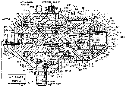
FIG. 1 is a sectional view of a plasma jet torch
embodying the principles of this invention;
FIG. 2 is a sectional view along line 2-2 of FIG. l;
FIG. 3 is a sectional view along line 3-3 of FIG. l;
FIGS. 4 to 7 are test tabulations and corresponding
graphs illustrating torch operating parameters ; and
FIG. 8 is a fragmentary sectional view showing an
embodiment of the FIG. 1 torch without a cathode well.
Detailed Description of the Preferred Embodiment
Referring to FIGS. 1 and 2 of the drawings, my
improved torch indicated generally at 10 comprises a
cathode section shown generally at 12 and a collinear
7~ ~
~12-005
anode section indicated generally at 14 mounted in an
insulating body or housing shown generally at 16 made of
a suitably impact-resistant material such as Delrin
resin. The cathode and anode sections as well as the
housing are each composed of a plurality of annular
components or parts which, when assembled, define
passageways for supplying a gas to the torch to stabilize
and lengthen the arc established between its electrodes
and for circulating water through the torch to cool its
various parts, particularly the electrodes.
The cathode section 12 includes a tubular cathode
holder 18 made of a conductive metal such as brass.
Holder 18 has an axial bore 22 whose front end is
counterbored at 24 to accept a brass sleeve-like water
separator 26. The outside diameter of the water
separator is slightly smaller than the diameter of the
counterbore 24 so that an annular passage or space 28
exists between the water separator and the wall of
counterbore 24. The rear end of the separator is necked
down at 26a and fits snugly within the cathode holder
bore 22. That neck 26a is grooved circumferentially to
accept an O-ring seal 32 which establishes a fluid-tight
seal between the rear end of the water separator and the
wall of bore 22. The front end of the water separator
has a radial flange 26b which seats in a radial
enlargement of counterbore 24a at the entrance to the
counterbore. Also, a multiplicity, e.g. twenty, of
rearwardly directed holes 34 are spaced around the
separator wall adjacent its Elange 26_.
A cathode 36 seats inside separator 26. The cathode
is a cup-like member made of a heat resistant conductive
metal such as a tellurium-copper alloy and defines a well
37 at the longitudinal centerline of the torch.
Typically, the well is on the order of 0.875 inch in
5 ~ !
- G12-005
11
diameter and has a depth which may vary depending upon
the operating voltage of the torch. Usually, the well
depth ranges from 0.375 inch to 1.38 inches. The open
front end of cathode 36 has a radial flange 38 which is
sized to seat in the counterbore enlargement 24a, an O-
ring seal 42 being provided in the edge of the flange to
form an annular seal at that location. The outside
diameter of cathode 36 is somewhat smaller than the
inside diameter of the water separator 26 thereby leaving
an annular passage 44 between the separator and the
cathode. Also, an annular slot 45 extends into the
cathode flange from the rear as shown in FIG. 1 so that,
when the cathode is seated in its holder 18, that groove
forms an end wall for the annular passage 44. Thus, when
cooling-water is delivered to the bore 22 of the cathode
holder through a fitting 46 connected to the rear end of
the holder, it is conducted along passage 44 and is
redirected through holes 34 back along passage 28 so that
the cooling water makes two passes by the cathode thereby
efficiently cooling that member. The water is conducted
out of passage 28 by an array of holes 47 in the cathode
holder wall to a circumferential groove 48 in the outside
surface of the holder.
The left-hand end wall 36a of cathode 36 is more or
less conical and projects into the necked-down portion
26a of the water separator 26. The inside surface of
that end wall has a recess 49 for seating a cathode
emitter 52 which extends out appreciably, e.g. about 0.34
inch, from the cathode end wall 36a at the centerline of
the well 37. That member is made of a suitable heat-
resistant conductive material such as a tungsten alloy
and preferably it has a beveled or pointed end 52a. The
emitter is retained within the recess 4~ by an
appropriate bonding agent such as solder, a weep hole 54
G12-005
12
being provided at the bottom of the recess to drain away
excess solder when the electrode is seated.
Completing the cathode section 12 is an annular gas
injector or swirl ring 58 made of a metal such as
5 tellurium-copper alloy which is engaged to the front end
of the cathode holder 18. The gas injector is basically
an internally threaded ring which screws onto a reduced
diameter, exteriorly threaded end segment of the cathode
holder, the joint between those two members being sealed
by an O-ring 62 The gas injector has a radially
inwardly extending flange 58a which overhangs the
adjacent end of cathode 36 so that, when the gas injector
is t~rned down onto the cathode holder as shown in FIG.
1, it retains the water separator 26 and the cathode 36
inside the cathode holder 18. Preferably the flanged end
of the gas injector is grooved to seat an O-ring 60 to
provide a seal between the gas injector and the torchls
anode section 14. As best seen in FIG. 2, the gas
injector includes a multiplicity, e.g. twenty to thirty,
of unusually large, e.g. 1/16 inch, holes 64 spaced
uniformly around its flanged end. These holes or
passages extend from the outer surface of flange 58a to
the inner surface thereof and they are angled so that
they intercept the axial hole through the flange
tangentially.
As stated previously, the cathode section 12 is
retained within the insulating housing 16. Actually
housing 16 is composed of three different sections,
namely a rear section 16a, a middle section 16b and a
front section 16c, the cathode section being snugly
received in an axial bore 72 in the rear housing section
16a. The cathode holder 18 is exteriorly threaded
adjacent its rear end at 7~ to receive an internally
threaded retainer ring 75. Ring 75 seats in an annular
G12-005
13
groove 76 formed in the rear end wall of housing section
16a. Ring 76 and thus the entire cathode section 12 are
anchored to that housing section by threaded fasteners 78
which extend through holes 79 spaced around ring 76 and
screwed into threaded holes 80 in the housing section end
wall. An O-ring 65 is seated in the wall of bore 72
adjacent its rear end to provide a seal there between the
housing section and the cathode holder. Also, an
insulating plastic cap or cover b7 engages over the rear
end of the cathode holder lR and the water fitting 46
which protrude from the rear end of the housing section
16a.
As best seen in FIGS. 1 and 2, when the cathode
holder 18 is seated properly in bore 72, its
circumferential groove 48 is located directly opposite a
pair of arcuate slots 81 in the wall of bore 72 at
opposite sides of the housing section 16a. Those slots
intercept the left-hand ends of two groups of
longitudinal passages 82, there being, say, five such
passages in each such group so that cooling water from
the holes 47 in the cathode holder can flow into those
passages. Passages 82 extend to the front end of housing
section 16a where they intercept a pair of arcuate
notches 84 thereat which are aligned with the slots 81.
That housing section end abuts the rear end of the middle
housing section 16b which thus forms a wall for those
notches so that they resemble the slots 81. For ease of
illustration in FIG. 1, we have shown one slot 81 and the
left-hand segment of a passage 82 near the top of housing
section 16a and the right-hand segment of a passage 82
and a notch 84 near the bottom of that housing section,
the continuity of those passages being indicated by the
short arrows A.
G12-005
14
Still referring to F~GS. 1 and 2, a vertical
counterbored passage 86 is present in the top wall of
housing section 16a, the passage heing internally
threaded to receive a threaded gas fitting 88. An O-ring
92 is seated in a circumferential groove in the gas
fitting to provide a fluid-tight seal between that
fitting and the passage wall. Fitting 88 is adapted to
be connected to a source of a suitable plasma-forming
working gas such as nitrogen, helium, argon or the like.
A smaller passage 94 extends from the bottom of passage
86 to a relatively wide groove 96 inscribed in the wall
of the housing section bore 72. When the cathode section
12 is seated in the housing section 16a as shown in FIG.
1, it forms with groove 96 an annular passage which
extends all around the gas injector 58. Thus the working
gas supplied to the torch through fitting 88 is conducted
uniformly to all of the holes 64 in the gas injector.
The cathode section 12 is separated from the anode
section 14 by an electrically insulating ring ~8 made of
ceramic or other comparable heat-resistant material which
butts against the gas injector 58 in the bore 72 of
housing section 16a. In this, it helps to define the
annular passage surrounding the gas injector 58. The O-
ring seal 66 at the end of the gas injector engages ring
98 to provide a fluid-tight seal between those two
members.
Anode section 14 comprises an elongated primary
anode 104 made of a heat-resistant metal such as a
tellurium-copper alloy. Anode 104 is a tubular member
having a frustoconical or tapered passage or bore 106
which is coaxial with the cathode well 37. Typically,
the bore has a length of about 2.68 inches and 2 to 4
taper with the front or exit end of the bore being from
0~325 to 0.425 inch in diameter, 0.375 inch being the
`.dg~ '
G12-005
optimum size. The anode is terminated by a pair of
circular flanges 108 and 110 whose diameters are slightly
less than that of bore 72 in housing section 16a
permitting the left-hand end segment of the anode 104 to
be slid into bore 72. Flange 108 is notched at 112 to
provide only eno~gh clearance for the spacer ring ~8 so
that the rear end of the anode is spaced slightly from
the forward end of cathode 36. This provides an annular
gap 113 between the cathode and the primary anode 104
through which the working gas issuing from the holes 64
in the injector 58 may pass into the well 37 and the
anode bore 106. Preferably, the rear end of bore 106 has
a somewhat smaller diameter than well 37 so that an
annular shoulder 114 is disposed opposite the mouth of
the well for reasons that will be described later.
A wall of the anode notch 112 is grooved to accept
an O-ring 115 to provide a fluid-tight seal between that
wall and the spacer ring 98. Another O-ring 116 is
seated in a groove in the bore 72 wall opposite flange
108 to provide a fluid-tight seal at that location. The
primary anode 104 projects from the forward end of
housing section 16a through the bore 118 of housing
section 16b into the bore 122 of housing section 16c,
those two bores having the same diameter as bore 72 so
that the anode flange 110 is received snugly in the
forward housing section bore 122. An O-ring 124 is
seated in a groove in the wall of bore 122 opposite the
edge of flange 110 to provide a fluid-tight seal between
that flange and the housing section 16c.
Surrounding the primary anode 104 between its
flanges is a tubular water separator 126. The separator
has a central frustoconical stem 128 terminated by radial
flanges 130 and 132. Flange 130 at the rear end of the
separator seats against flange 108 of the primary anode
G12-G05
16
and extends out to snugly engage the wall of bore 72 in
housing section 16a. The opposite flange 132 engages
against the primary anode ~lange 110 and e~tends out to
the wall of bore 122 in housing section 16c. A third
flange 136 extends out radially from stem 128 to engage
the wall of bore 118 in housing section 16b. That last
wall is grooved to receive an O-ring 138 for providing a
fluid-tight seal between section 16b and flange 136.
Preferably, the water separator 126 is split lengthwise
into two mirrcr-image halves so that it can be engaged
around the primary anode before that anode is received
into the bores of housing sections 16a to 16c.
As shown in FIG. 1, when the primary anode and its
water separator are seated inside the housing sections,
the separator flanges 130 and 136 along with the housing
section bore walls 72 and 118 define an annular space
142, sectors of which lie opposite the notches 84 in the
housing section 16a which communicate with passages 82.
The inner diameter of the water separator 126 is slightly
larger than the o~ter diameter of the primary anode stem
106 so that an annular passage 144 exists between the
water separator and the anode stem. Also, a circular
array of holes 146 is formed through the wall of
separator 126, the holes leading from space 142 to
passage 144. These holes are angled rearwardly as shown
in ~IG. 1. Further, an annular yroove 148 is inscribed
in the forward face of the anode flange 108 which opens
to the holes 146 as well as to passage 144 and it is
oriented to provide smooth fluid flow between those
openings.
The primary anode flange 110 also has an annular
groove 152 that is positioned opposite the forward end of
passage 144. A circular array o~ rearwardly directed
holes 154 extends through the wall of the water separator
~ S ~
G12-005
17
from groove 152 to an annular space 156 located between
the separator flanges 132 and 136. As best seen in FIGS.
1 and 3, the space 146 opens to a pair of diametrically
opposite arcuate notches 158 in the rear end wall of
housing section 16c. The notches 158, which are similar
to the notches 84 in housing section 16a in that they are
also bounded by housing section 16b, intercept the ends
of two groups of five passages 162 extending lengthwise
through the wall of housing section 16c. These passages
lead to a pair of diametrically opposite grooves 164
inscribed in the wall of the housing section bore 122,
only one of which is shown in FIG. 1. These grooves are
similar to grooves 84 described above.
Thus the cooling water from passages 82 is conduc~ed
into the annular space 142 and circulated through holes
146 into the annular passage 14g surrounding the primary
anode. Then it is routed back through holes 154 to the
annular space 156 before it is conducted via the
notchesl53 to passages 162. Thus, the primary anode 104
is also effectively jacketed by two layers of cooling
water.
Still referring to FIG. 1, positioned forwardly of
the primary anode 104 is a cylindrical secondary anode
166 made of the same material as the primary anode. Its
rear end has a radial flange 172 which seats against th~e
front end of the primary anode 104 making good electrical
contact therewith and it also fits snugly within the bore
122 of housing section 16c. An O-ring 173 is recessed
into bore 122 opposite the flange edge to provide a seal
between that flange and the housing section 16c. The
secondary anode projects out from the front of the
housing section 16c and its front end carries a radial
flange 174 whose inner edge is beveled at 174a. The
axial passage 176 through anode 166 has a diameter which
~12-oo5
18
is appreciably larger than the diameter of the front end
of passage 106 through the primary anode 104.
Preferably, anode 166 has a length of about 1.65 inches
and a diameter of from 0.5 inch to 1.125 inches with
0.876 inch being an optimum size. This creates a wide
annular shelf 178 at the front face of the primary anode
104 which extends between the inner wall of the secondary
anode and the circular knife edge at the end of anode
passage 106. By "knife edge", I mean an edge with no
radius formed by intersecting surfaces making an angle of
at least 270 and which is uniformly sharp around its
circumference as shown in FIGS. 1 and 3. As best seen in
FIG. 3, the front face of the primary anode flange 110
has a peripheral notch 182 to provide an annular space
between that flange and the secondary anode flange 172.
F~rthermore, a circular array of radial slots 184 are
inscribed in the front face of flange 110 which extend
from notch 182 to locations on shelf 178 opposite the
secondary anode passage 176.
Referring to FIG. 1, surrounding the secondary anode
166 is a water separator 192 formed as a split sleeve
which fits snugly between the secondary anode flanges 172
and 174. Its inner diameter is slightly larger than the
o~lter diameter of the central portion of that anode,
leaving an annular passage 194 between the water
separator and the anode. A circular array of radial
notches 196 is formed in the rear end wall of the water
separator. These notches are located directl~ opposite
the grooves 164 formed in the bore 122 of the housing
section 16c so that cooling water can flow from those
grooves through the notches into the annular passage 19~.
The opposite or front end of the water separator is
also provided with a circular array of radial notches 198
which extend Erom the outer wall almost to the inner wall
~ JJ~ ~ ,
G12-005
19
of that member. Further, a circular groove 200 is
inscribed in the rear face of the secondary anode flange
174 so that the water can flow from passage 19~ via that
groove radially out through notches 198 to the front ends
of a circular array of longitudinal slots 202 formed in
the beveled front end porton of housing section 16c. An
O-ring 204 is seated in a circumferential groove in water
separator 192 to provide a seal between the water
separator and the housing section 16c. The rear ends of
slots 202 communicate with an arcuate groove 206
extending around the perimeter of housing section 16c.
As shown in FIG. 3, a group of four large passages 208
extend lengthwise through the wall of section 16c from
groove 206 to the rear end of section where they register
with similar lengthwise passages 210 extending through
the wall of housing section 16b and with a like number of
passages 212 extending through the wall of housing
section 16a which lead to a recess 214 in the underside
of housing section 16a to which the cooling water from
slots 202 is conducted. The mouth of recess 214 in
housing section 16a is closed by a conductive metal plug
228 which functions both as an anode conductor and a
connector for a cooling water outlet fitting 229 which is
screwed into a threaded hole 230 in that plug. An O-ring
227 is seated in a circumferential groove in the plug to
provide a seal between the plug and the wall of recess
214 and the plug is held in place by threaded fasteners
231 which extend through passages 232 in the plug and are
turned down into threaded holes 233 at the underside of
housing section 16a.
As shown in FIGS. 1 and 3, the three housing
sections are secured together by four bolts 234 which
extend rearwardly through countersunk holes 235 in
housing section l~c and through registering holes 236 in
75~3 .
Gl~-005
section 16b and are turned down into threaded holes 238
in the front end of housing section 16_.
A conductive metal shell 242 is engaged over the
front end of the torch. The lead ing end of the shell
5 interfits with and retains the front end of anode 166
which projects from housing section 16c. The shell
extends back around housing sections 16c forming a cover
for the cool ing water slots 202. It also encircles
section 16b and a portion of section 16a. The shell is
10 interiorly threaded at 243 adjacent its rear end so that
it can be screwed onto an exteriorly threaded segment 244
of housing section 16a. An O-ring 246 is provided at the
boundary between the secondary anode flange 174 and the
shell to provide a seal at that location. Another O-ring
15 248 provides a seal between the housing section 16c and
the shell where the shell is threaded onto that member.
As shown in FIG. 1, the shell has a radial flange 242a at
its rear end which carries a conductive lug 252 which is
anchored to plug 228 by one or more bolts 254 each of
20 which extends through the lug into a threaded hole 256 in
the plug. Thus there is a good electrical connection
between the secondary anode 166 and Eitting 229.
Cooling water is supplied to torch 10 by way of
fitting 46 and flows through the torch along the
25 circuitous path indicated by the dot-dash arrows in FIG.
1, leaving through fitting 229. In so doing, it is
brought into very intimate heat exchange contact with all
of the torch's elec~rode structures that are subjected to
~he hot plasma produced when the torch is in operation.
30 Consequently, those parts do not suffer heat damage
despite the high temperatures developed by the torch.
The torch is connected electrically by way of its
fittings ~6 and 229 to an appropr iate DC power supply
260. Electrons flow from the power supply to cathode 36
s~ ~
~12-005
21
via holder 18 and the gas injector 58 and emerge from its
emitter 52 to form an arc column indicated generally at
262. The arc column extends axially along the pathway
formed by well 37 and the anode passages 106 and 176 and,
in this nontransferred mode of operation, the arc fingers
262a impinge against the beveled surface 174_ of the
secondary anode 166 at the leading end of the torch. The
return path for the electrons is along the conductive
shell 242 to lug 252 and plug 228 to the positive
terminal of power supply 2fiO. The arc is typically
initiated by momentarily supplementing the DC voltage
with a high frequency alternating voltage.
The working gas for torch 10 is supplied via fitting
88 which is conne~ted to a suitable source of such gas.
As noted previously, the working gas may be nitrogen,
argon or other gas depending upon the particular
application. The gas flows via passage 94 to the annular
groove 96 in housing section 16a which surrounds the gas
injector 58. The gas issues from the holes 64 in the
injector so that it enters the gap 113 between the
cathode 36 and primary anode 104 as a swirl or vortex as
indicated by the solid line arrows in FIG. 1.
The main body of the vortex flow enters the primary
anode bore 106 and becomes heated and dissociated by the
arc stream forming a plasma which travels along the bore
176 in the secondary electrode 166 emerging from the
front of the torch as a plasma effluent shown generally
at 266 in FIG. 1. Due to the presence of the annular
shoulder 114 at the mouth of well 37, a small portion of
the incoming gas swirl is deflected into the well and is
recirculated there. This "dead" gas vortex still helps
to stabilize the segment of the arc within well 37.
In some applications, it is desirable to expose the
workpiece being heated to a certain atmosphere to obtain
'`;d ~ 3
G12~005
22
a particular reaction. For e~ample, it may be de~ired to
heat the workpiece in the presence of an oxidizing or
reducing atmosphere This is usually accomplished by
introducing a gas, oxygen, for example, into the plasma
stream issuing from the mouth of the torch. Provision is
made in the illustrated torch 10 for connecting a second
gas fitting shown generally at 270 in FIG. 1 so that a
secondary gas supplied to that fitting is conducted
through longitudinal passages (not shown) in the wall of
housing 16 to the annular space provided by the notch 182
at the front end of the primary anode. The secondary gas
then flows throu~h the radial notches 184 at the front of
that anode and is released at the shelf 178 into the
plasma stream passing through the secondary anode bore
176. The secondary gas comingles with and is heated by
the hot plasma thus forming part of the effluent 26~
issuing from the torch to the workpiece. Also, in some
instances, it may be desirable to introduce particulate
matter such as metallic powder in the effluent so that
the powder will be melted before being deposited at the
workpiece. In the present torch, a set of nozzles for
dispensing such particulate material can be mounted at
the mouth or exit end of the torch so as to eject such
material into the plasma effluent. One such nozzle is
indicated in dotted lines at 274 in FIG. 1.
During the operation of the plasma jet torch
described above, the origin of the electron stream
emitted from the cathode structure 52 projecting out ~rom
the bottom of well 37 is stably positioned on the
emitting structure 52. Accordingly, the surface of that
structure suffers a minimum amount of erosion and damage
due to temperature cycling. Also, the introduction of
the pressurized working gas into the arc pathway through
a large number of uniformly distributed large injection
`~ ~2~2~7~8
G12-005
23
holes reduces the pressure drop of the gas as it enters
the pathway so that there are essentially no ~luctuations
in the incoming gas flow due to any minute pressure
fluctuations that might be caused by minute movements of
the arc segment in well 37. As a result, a strong very
uniform gas swirl surrounds the arc along substantially
its entire extent within the arc pathway. The velocity
or intensity of this swirl increases progressively due to
the continuous convergence of the primary anode bore 106
and tends to squeeze the arc and keep it centered on the
axis of the arc pathway all the way to the exit end of
the primary anode. Consequently, the striking of arc
fingers from the main body of the arc to the wall of bore
106 does not occur.
Further, the issuance of the hot gas and plasma
through the knife-edged orifice at the exit end of the
primary anode into the space bounded by the much larger
diameter secondary anode relatively remote from the arc
pathway inhibits the tendency for arc fingers to strike
to the wall of the secondary anode bore 17~.
Resultantly, the arc 262 propagates all the way out to
the very end of the secondary anode before striking over
to that anode edge 17~a as arc fingers 262a except when
operating at high currents in which case some of the arc
strikes in the bore of the secondary anode 176. These
factors maximi2e the arc voltage drop. These same
factors along with the above described very efficient
redundant electrode cooling arrangement in torch 10
maximizes the current that can be drawn by the torch
without damage to its electrodes and other parts. ~s a
result, a maximum amount of power can be delivered to the
arc.
Further, because the gas stream is introduced into
the arc pathway as an intense uniform swirl which
;
G12-005
~4
progressively increases in intensity and constricts as
described above, there is very intimate contact between
the yas and the arc stream 262 with the result that there
is a very efficient transfer of energy to the plasma so
that the heat output from the torch is a maximum for a
given amount of input power. Yet the present torch will
still operate very effectively at lower power levels and
gas flow rates. In actual tests, the present torch has
been operated at current levels ranging from 20 amps to
500 amps at various gas flow rates varying from 150 to
2300 SCFH without failure at efficiencies ranging fro~
72~ to as high as 85% while yielding enthalpies extending
from as low as 500 BTU/lb. to as high as 7,000 BTU/lb.
FIGS~ 4 to 7 are tables and corresponding graphs
illustrating the results of some of these tests showing
enthalpies achieved at different torch power levels and
working gas flow rates. It is important to note that, as
clearly shown by the constant enthalpy lines E in the
graphs, the same heat output can be obtained with widely
varying power and working gas flow rate levels.
Accordingly, the same torch can be used in situations
where there are different constraint~ on those factors.
Further, we have found that, by shortening the
primary anode somewhat and electrically isolating the
primary and secondary anodes of torch 10 by placing an
insulator made of a temperature-resistant material such
as boron nitride between the primary and secondary anodes
104 and 166 as indicated in dotted lines at 278 in FIG.
1, the torch can draw up to 50% more current without the
arc striking to the wall of the primary anode. As can be
appreciated, this drastically increases the output power
of the torch enabling it to achieve enthalpies of more
than 18,000 BTV/lb.
d ~ 5 ~
Gl2-005
For some working gas environments, it is desirable
to position the free end of the cathode emitter structure
closer to the primary anode 104 so as to avoid excessive
current leakage to the wall of the primary anode. FIG. 8
shows a torch embodiment particularly suited for high
current, high enthalpy operation in order, for example,
to spheroidize refractory materials to make refractory
powders and particles. The components of this embodiment
common to the FIG. l torch carry the same identifying
numerals. The FIG. 8 torch differs ~rom the one
described above in that it has a cathode 36' in the form
of a solid metal block. A recess 49' is present at the
end of the block in which is seated a generally
cylindrical cathode emitter struct~re 52'. In other
words, the structure 52' is mounted adjacent to the swirl
ring 58 rather than at the bottom of a well. Structure
52' extends along the arc passageway axis partway into
bore 106 of primary anode 104 and preferably its free end
is conically tapered as shown in FIG. 8.
When this torch is operated with a working gas such
as nitrogen, the arc current is sufficient to cause
dissociation of the gas so that upon recombination
thereof, torch enthalpies of 15,000 Btu/lb. or more can
be attained quite easily. This heat is sufficient to
spheroidize even highly refractory materials such as
tungsten carbide and zirconium oxide. Still, even though
the working gas dissociates easily, because the cathode
structure 52' projects appreciably into the anode bore
106, e.g.l one inch for nitrogen and about two inches for
argon (with anodes electrically isolated as described
above), excessive premature arcing to the primary anode
wall is avoided. Alternatively, the projecting of the
emitter structure into the anode bore can be accomplished
by lengthening the emitter structure 52' in the FIG. 1
5~ ~
G12-005
26
torch embodiment so that it extends out of the well into
bore 106.
In the case of a working gas such as hydrogen which
is much less prone to ionize, on the other hand, the
cathode emitter structure should be positioned even
further from the anode 104 than is shown in FIG. 1, say,
by making the cathode well deeper than is shown there.
Also, in some cases where it is desired to operate the
torch at reduced voltage, say, because the open circuit
voltage of the torch's power supply 260 is limited, the
short emitter structure 52 in FIG. 1 may be positioned in
a cathode well which is relatively shallow, e.g., one-
half to one inch deep. Actually, it would be desirable
to provide suitable means for movably mounting the
emitter structure 52' in the cathode so that its position
along the torch axis could be varied to accomodate
different working gas mixtures and operating conditions
with with the free end of that structure being located
along the arc passageway so as to avoid excessive current
leakage or premature arcing to the anode walls.
In addition to the cost savings resulting from the
efficient operation of torch 10, the torch is composed of
parts which are relatively easy to make. Further, as
described above, they can be pieced together quite
quickly by the average production worker. Consequently,
the overall cost of making and assembling the torch can
be held to a minimum. Considering also that the present
torch should reduce the need for stocking different
torches for handling applications requiring different
torch powers, a considerable overall cost savings results
through the acquisition and use of this torch.
It will thus be seen that the objects set forth
above, among those made apparent from the preceding
description, are efficiently attained, and, since certain
- 27 - 6~21-3~1
changes may be made in the above construction without departing
from the scope of the invention, it is intended that all matter
contained in the above description or shown in the accompanying
drawings be interpreted as illustrative and not in a limiting
sense.
It is also to be understood that the following claims
are intended to cover all of the generic and speci-fic fea-tures of
the invention herein described.