Note: Descriptions are shown in the official language in which they were submitted.
3247-16
~P~ C~
~ ~ 3~J1 .~
The present invention relates to water samplers of the
-type known as in situ pump samplers. The invention pari`icularly
relates to in situ pump samplers for trace substances in lake
water or seawater, with a particular application to seawater.
The use of in situ concent:ration or various trace sub-
stances in seawater offers clear advantages over conventional
methods requiring bulk water sample collection and s'hipboard ex~
traction. For some substances of oceanographic, geochemical, or
toxicological interest the degree of concen-trati.on required to
ensure reasonable accuracy and preclsion of analysis necessitates
the handling of very large vol.umes of sample. 'Ln the past,
samplers have been built which collected thousands of liters of
seawater and required twelve or more hours of station time for
sampling and processing, in order to collect enough of some rare
component for reliable analysis. For other components, large
samples were needed in order -to overcome the problem of large and
variable background or blanX values.
Until fairly recently, conventional methods of collec-
tion and concentration seemed adequate for most trace substances,
since the analytical limits of detection exceeded apparent levels
of contamination. However, a review of the earlier work reveals
: that in many ins-tances contamination actually acquired during
collection and extraction comprised the major part of the reported
concen-trations. For an even greater number of su'bstances, more
recent methods of analysis provide sensitivities which far exceed
the capability of the most careful water sampling regime to
deliver contamination-free sam~les.
~, .. :- .
: '
An examination of the possible sources of contamination
has provided insi~hts useful in devising a more ef~ective sampling
strategy. The sources of contamination include the hydrographic
wire carrying the sampling container and the sampling container
itself. The early samplers, the Knudsen and Nansen bottles, used
metal alloy valves requiring heavy application of stopcock grease,
and were -thus unfit for either trace metal or trace organic
analyses. More recent samplers often contain both trace metals
and plasticizers in the plastic usecl in their construction. The
research vessel on station is surrounded by an aura of waste pro-
ducts -through which the sarnpler must pass. Once the sample has
been collected and brought on board for extraction, the usual
hazards of contamination common to any laboratory are present,
augmented by those special contaminants resulting from shipboard
operations.
The oceanographic literature provides evidence oE the
considerable effort expended in attempts to reduce contamination.
Hydrographic wires encapsuIated in polymers, or made of materials
such as Kevlar (Trade Mark) have been described, as have samplers
made of noncontaminating materials or employing a large volume/
internal surface ratio. Remote sampling buoys have been utilized,
and clean rooms have been fitted to some research vessels. While
all of these strategies Eor avoiding sample contamination have met
with some success, they suffer from the limitations of inconven-
ience, high cost, lack of versatility, and the need fox large
vessels with special winches or adequate deck space. At a time
when the availability and expense of big ship operation will
" ,
c
J~
inevitably force the oceanographic community, outside of the large
government laboratories to do much of its sample collecting froM
ships of opportuni-ty, these do not appear to be useful strategies
for the university or -the small government laboratory.
In situ pumping ofEers a means of concen-trating various
trace substances from seawater while diminishing much of the
potential for contamination inherent in water sample collection
and shipboard ex-traction. E'urthermore, where large samples are
desired, the volume sampled is ]imited only hy the capacity of the
power source and the efficiency and capacity of the method of
concentration.
For many chemical entities, the concentrator of choice
is some variety of adsorption column~ In recent years the chem-
ical literature has overflowed wit'h reports of newer and better
column pac]cings, wi-th capabilities for concentrating an ever-
increasing list of trace substances.
Some studies in which in situ pumping has bean used have
been described in the oceanographic literature. While the great
potential of the method is apparent from these publications, the
pumping systems used are invariably large, heavy, and are powered
either from the surface or b~ specially prepared lead-acid storage
batteries.
A pumping system powered from the surface requires a
winch carrying conductor cable and equipped with slip rings. Such
winches are not common either on ships of oppor-tunity or on the
smaller oceanographic research vessels. If a reasonable amount of
power i5 needed, the system mus-t ei-ther be limited to shallower
_ 3 ~
~ .
.~.
depths or it must transmit a very large voltage at the surface in
order to overcome the power loss in transmission.
The lead-acid storaye batteries typica~.ly used for
in situ pumping have proven effective but both inconvenient and
hazardous. These batteries require a means of pressure equili-
bration, and provision must he made for degassing and for insula-
tion of their terminals.
To obtain the most ou-t of in situ pumping versality of
the device must be considered. The pump sampler shoul.d be capable
of pumping accurately whether large volume samples or smal.l volume
samples are involved. The system should be light and compact and
should be of a nature such that more -than one unit could be accom-
modated on a hydrographic wire in a single cast, so that depth
profiles may be obtained, if desired, the sys-tem should be capable
of activation and deactiva-tion by a very simple contrivance and
the device should be capable of alignmen-t during operation -to
minimize the effects of sample contamination.
According to the present invention there is provided a.n
in situ water pump sample:r comprising a f.rame member; swivel
attachment means for attaching the frame member to a hydrographic
wire to permit 360 pivoting of the frame member about the longi-
tudinal axis of the hydrographic wire; a self-contained pump
sampler member; a hub-like means adapted to be mounted on the
frame means to pivotally attach the pump sampler member to the
frame means to permit rotation of the pump sa~pler member on the
frame about a rotation axis normal to the longitudinal axis of the
hydrographic wire; and means responsive to sequential command
~ 4 --
:
. , : ~
J~
signals to permit incremental rotation of the pump sampler mernber
on the frame member about the rotation axis from an initial
lowering posi-tion, in which the pump sampler mernber extends in a
generally up-and-down conEiguration, to an intermediate sampling
position, in which the pump samPler member extends it generally at
right angles to the lollgitudina] axis of the wire, to a final
retrieval position in which the pump samp]er member extends in a
generally up-and-down configuration on the frame.
Pre~erably the pump sampler member is generally of
tubular configuration, generally radiating, spoke-like from the
hub-like means; and includes a water sample pump having a pump
head on the distal end of the pump sampler member, which pum~ head
is located above the hub-like means in the initial lowering
position and below the hub-like means in the retrieval position.
According to a preferred embodiment the frame member is
a rectangular plate-like mernber with the hub-like means being
disposed s~bstantially centrally of, and ex-tending through, the
plate-like member.
According to a feature of the invention directional
vanes may be provided at one end of the tubular configuration pump
sampler means, the vanes being responsive to the action of water
currents, when the device is submersed and deplo~ed ln its inter-
mediate sampling position, to orient the pump sampler relative to
the longitudinal axis of the hydrographic wire on the swivel
attachment means to pivot the pump head into the current, upstream
of the wire.
-- 5 --
.
- '
, ' ~.
~ 6~
In a preferred configuration the hub-like means includes
bearing members for pivotally ak-taching the pump sampler member on
the hub~l.ike means; and a tri.gger operated indexing mechanism is
provided for locking the pump sampler member in the hub-like means
in each of the lowering, intermediate and retrieval positions.
According to a further preferred feature of the in-
vention the pump sampler member is mounted in a rotationally out-
of-balance manner on the hub-like means and a trigger ac-tuating
mechanism is mounted on the frame 5C) as to operatively engaqe ancl
actuate the indexing mechanism in response to sequential command
signals generated by primary messenclers dropped down the hyd.ro-
graphic wire.
According to still a further preferred feature of the
invention the bearings include means to attach secondary
messengers and to release them sequentially in response to the
signals generated by the primary messengers whereby to drop the
secondary messengers down the hydrographic wire -to activate a
secondary in situ pump sampler therebeneath on the wire.
In order to provide for greate.r flex.ibility of opera-
tion, the water sample pump is preferably provided with a plur-
ality of interchangeable pump parts to vary its pumping capacity.
Additionally, the water sample pump head may be adapted
to receive a sample concentrating column.
The water sample pump conveniently may be provided with
inlet and outlet flow lines; a one way valve member in the inlet
and in the outlet flow line and actuated on initiation of pumping
action by the water sample pump ko open and permit commencement of
,~ ~
-- 6 --
: ~ ... . . .
, ~ "
:
~, " ~ ,.:, ~ , ,
water sample tak~ng, and, on termination of pumping action, to
close and seal the lines.
Furthermore the pump sampler means may include a self-
contained battery pack to operate the water sample pump and
preferably is provided with a visual counter to display elapsed
time of pumping.
In order to extend the operating time of the water
sample pump, the invention also envisages the provision of an
extended lie battery pack attachable to the frame.
The following is a description by way of example o
certain embodiments of the present invention reference being had
to the accompanying drawings in which:
Figure 1 is a schematic representation of the in situ
pump sampler device in an initial lowering position, an inter-
mediate, sampler, position being shown in chain dotted lines;
Figure 2 is a view similar to Figure 1 but taken from
the other side of the device and showing the pump sampler deployed
in its intermediate, or sampling, position;
Figure 3 is a view similar to Figure 1 but with a pump
sampler in a third, or retrieval position;
Figure 4 is a detail, exploded, view of the means for
mounting the pump sampler on its frame;
Figure 4a is a detail of part of apparatus shown in
Figure 4;
Figure 5 is a detail, exploded, view of the swivel
mounting for mounting the pump sampler on a hydrographic wire,
Figure 6 is a detail of the parts shown in Figure 5
- 7 -
'~
assembled on the hydrographic wire;
Figures 7 and 8 are details of one-way valve units pro-
vided in inlet and outlet water lines to the pump sampler;
Figure 9 is a detail of a mechani.sm for releasing
secondary messengers from the pump sampler, down the hydrographic
wire to a second in situ pump sampler positioned on the wire
beneath it; and
Figure 10 is a cross-sectional view through an assembled
structure of certain o:E the parts shown in Figure 4.
Turning now to the drawings.
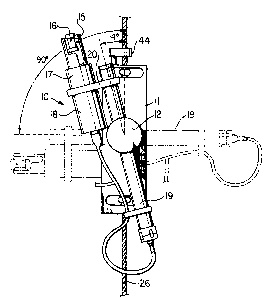
An in situ pump sampler member lO, generally GE tubular
configuration, is mounted on a rectangular plate-like frame member
ll by means of a hub-like member 12. The pump sampler member 10
includes a water sample pump 15 provided with interchangeable
heads 16 at the distal end of member 10, providing for a variety
of pumping rates. The water pump 15 is driven by an electric
motor 17 housed in the tubular continuation 18. The motor 17 is
powered by batteries (preEerably NiCad batteries) in a tubular
electronics pack l9 also forming part of the pump sampler member
lO and braced thereto by brace member 20 to ~orm a unitary body.
The pump sampler member lO radiates spoke-like from the hub-like
member 12.
Turning to Figures 2, 5 and 6, the frame member ll is
provided with two swivel mount members generally indicated at 25,
for attachment of the pump sampIer member lO to a hydrographic
wire 26 to permit a full 360~ rotation of the frame ll and its
pump sampler member lO about the lon~itudinal axis of the hydro-
- 8 -
... .
::
~.. . .. . .
,,
' `` ` ` ' ~ '' :
.
3A..~
graphic wire 26. The swivel 25, and there are two of them, asseen in Figure 2, comprises a wire clamp 27 located in the base of
block 28. The wire clamp 27 is made of Delrin (Trade Mark) has a
vertical slot 30 leading to a central axial bore 31 that accommo-
da-tes the hydrographic wire 26. Normal to the hydrographic wire
26 in a slotted hole 32 is a holding bolt 33. Tightening the bolt
33, by its nut 34, secures the bolt 33 and by it, the clamp 27 to
the wire 26 (see Figure 6). The wire clamp 27 is clipped inko
position in block 28 with spring cli.p 35. Housed within the bloclc
28 above the clamp 27 is a bearing block 36 made of Delrin. The
clamp 27 has a conical nose 27a (see Figure 6) which interfaces
with a correspondingly conical sha~ed recess 36a in the underside
of block 36 and provides an impetus for centering clamp 27 on
block 36. The bearing block 36, like the clamp 27, has a central
hydrographic wire passing bore 26A and communicating slot 37. The
block 28 has an inwardly directed weight transmitting ledge 38
against which the upper face 39 of the bearing block 36, abuts.
When the swivel 25 is clamped, by means of the bolt 33 to the
hydrographic wire 26 and is attached by means of spring clip 35 to
block 28 the wei~ht of the pump sampler is transEerred from block
28 to face 39 of bearing block 36 and from the underface of
bearing block 36 to the upper face 40 of member 27. Thus the pump
sampler 10 mounted on its frame 11 is clamped the hydrographic
wire 26 by swivels 25 but because of the configuration of the
swivel, the frame 11, with the pump sampler unit 10, is free to
rotate a full 360 about the longitudinal axis of the hydrographic
wire 26 on the relatively friction free Delrin faces. The pack 19
~,;, g _
-
: ~ ~ ;,. . .. .
~ , ..'
''':''~
has orienting vanes or fins 21 (see Figures 2 and 3) which respond
to the action of watex currents and act to rotate the pump sampler
10 on its swivel about the wire 26 to point the pump head 16 into
the current, upstream of wire 26.
Referring now to Figures 1, 2, 3 and 4. The pump
sampler unit 10, including its electronics pack 19 (which conven-
iently has a titanium housing), is mounted on hub-like member 12
so as to radiate spo~e-like therefrom. ~s best seen in Figure ~,
tubular pack 19 passes through the bore in split collet 40 in
hub-like member 12 and is locked therein by means of a nut and
bolt clamping arrangemen-t 41.
As is seen in Figures 1, 2 and 3 the pump sampler unit
is mounted to occupy three indexed positions. ~he first position,
as seen in Figure 1, is the condition in which the pump sampler is
lowered on the hydrographic wire to the desired sampling depth.
Here the pump sampler uni-t 10 occupies a generally up-and-down
position on frame 11. As seen in Figure 1 the position of -the
pump sampler 10 is actually off-set, say, 1~ to the vertical.
When it is desired to start sampling the water, the pump sampler
10 is caused by means to be described hereinafter, to rotate,
under its own weight (it being mounted in an out-of-balance con-
dition) about a rotation axis of the hub normal to the longi-
tudinal axis of the wire 26 to an intermediate, sampling, position
in which the pump sampler member 10 extends generally at right
angles to the longitudinal axis of the hydrographic wire 26 (see
chain dotted line configuration in Figure 1 and full line condi-
tion in Figure 2). Here the pump sampler is locked in position
~.
-- 10 --
~6~
until such time as it is decided to retrieve the pump sampler, a-t
which time the inclexing mechanism, to be described, is operated to
permit the pump sampler unit 10 to occupy a third, retrieve posi-
tion (see Figure 3) in which -the pump sampler is generally in an
up-and-down condition, as shown in Figure 3, at an angle o, say,
16 from the vertical.
Although i-t is to be understood that the pump sampler
unit 10 could be mounted on the hub 12 so as to be rotatably
driven by any suitable means, such as a stepping motor, in re-
sponse to signals from the sur~ace, it is preferred to ef~ect thelocating of the pump sampler 10 relative to its frame 11 by means
of the inventive construction now to be described~
In Figure 2 it will be noted that the hydrographic
wire 26 passes through a canted slot 43 in an impact plate 44 and
into a vertical hole in the plate 44. The canted slot 43 ensures
that the vertical hydrographic wire 26 will not become disengaged
from impact plate 44. This arrangement enables a messenger
dropped down the hydrographic wire 26 from the surface, to hit the
impact plate 44~ (Messengers are devices well Xnown and often
used to activate instruments in oceanography. They are usually
made of brass and clip onto, and can fall rapidly down a sampling
wire, or the like.)
Turning now more specifically to Figures 4 and 10. The
hub-like member 12 includes bearings 46, 47 accommodating two sets
of Delrin roller bearings 48, 49. These roller bearings 48, 49
have Teflon (trademark) keepers and facilitate rotation. The
bearings are complete when the hub assembly passes into the re-
ceiver 50 thereof (with less than .005 centimeters clearance) and
. . .
- , ~.
,.
.
~282C3
is secured by nut 51.
When a primary messenger is clropped from the su,rface
down hydrographic wire 26 i-t contacts the impact plate 44 and
transmits a command signal. Beneath the impact plate 4~ and re-
ciprocably mounted in the block of swivel 25 is a Delrin rod 52
carrying a slotted wedge 53 at ,its l.ower end. ~s will be clear
from Figure 4, the impact plate 44 with its rod 52 and slotted
wedge 53 is maintained in a raised position by a compression
trigger spring 54. In its normal position the slotted wedge 53
barely engages an .indexing pin 55 stradd].ing it between a washer
56 and -threaded disc 58. ~owever, when the messenger delivers a
command signal to the impact plate 44 the rod 52 is driven down-
ward b~ the impact of the messenger and the slotted wedge 53
forces the indexing pin 55 to slide in its hole 56 in the face of
the fixed receiver member 50 and in its hole 57 in the plate-like
frame 11 to which member 50 is anchored, and out of its indexing
hole 60 in the rotating split-collet 40. The slotted wedge 53 in
forcing the indexing pin 55 outwardly from hole 60, compresses
return spring 61 and now that the indexing pin 55 is clear of the
split-collet 40, the pump sampler 10, by its own weight, rotates
in a clockwise fashion (as seen in Figures 2 and 4). The tip of a
retaining spring 63 is forced by tension spring 65 to ride the
surface of the threaded disc S8 and slips under the threaded disc
58 and thereby holds the indexing pin 55 out. This procedure
ensures that the indexin~ pin 55 does not return to the hole 60
which it occupied before the messenger was dropped. Nut 51, which
turns with collet 40 of the hub-like member 12, has slots in its
- 12 -
,. . .
,
:, ~ : . :
: :: , :
` ~ : .:
, ~
edge which accommodate an elbow 63e on the retaining pin 63 (see
Figure 4a). When the pump sampler 10 has pivoted through all but
a few degrees of its rotation prior to reaching its intermediate
position, the slot in the nut 51 (see Figure 4a) ends and the
elbow of the retaining pin 63 is forced backwards pulling the tip
of spring 63 from under disc 5~ thu!3 releasing the inde~ing pin
55. The indexing pin 55 is forced by its return spring 61 to ride
the surface of the collet 40 between holes 60 and 70 until the
next locking hole 70 is encountered. The pin 55 then slips into
hole 70 and rotation is stopped and the pump sampler indexed in
its intermediate, sampling, position. When the next sequential
command signal is required, at the end of pumping and prior to
re-trieval, a second messenger is dropped down the hydrographic
wire 26 again hits the impact plate 44 and the indexing operation
is repeated, with the pump sampler rotating to the position seen
in Figure 3 for retrieval, at which point the indexing pin 55 will
contact retaining hole ~1.
The strength of the spring 54 is selected so -that it
compresses sufficiently upon impact of the first messenger to
allow the indexing mechanism to disengage and operate but a-t the
same time to be able to rebound, with the weight of the first
messenger to allow the indexing mechanism to re-engage and lock
the pump sampler 10. Further, after the second messenger maXes
contact with the impact plate 44, and the pump sampler has pivoted
a second time, the spring 54 must be able to rebound carrying the
weight of two messengers to allow the mechanism to index and lock
in the third position.
- 13 -
-
,~
.. . : ..
" ~ ;:
'' : ~
..
: .
~ ~d ~ 2~.~
Because of the high stress encountered in stoppin~ the
orientating rotation of the pump sampler lO it is desirable that
the indexing pin 55 be strong. A suitable material has been found
to be in ultra high molecular weight polyethylene, a ma-teriaL with
a very high Izod impac-t strength and yet with sufficient yisld to
absorb the impact.
The water pumping operation of the pump sampler lO is
controlled electronically by circuit components housed within
pack 19. The control is based upon a clock module with a LCD
display 75 (See Figure 3~. The electronic control circuit which
is standard in design, preferably features a voltage re~erence and
comparator for detecting low battery voltage, and an alarm de-
tector circuit. A signal from either of these functions becomes
latched, and by controlling a transis-tor which actuates a relay
coil, disables the sampler until the system is recovered and re-
set. A magnetic switch (not shown) which turns the sampler pump
15 on, and ~hich is triggered in conventional fashion by the rota-
tion of the pump sampler lO on its hub from the initia~ lowering
position (Figure l) to the intermediate sampli~g position
(Figure 2), is located in series with a relay driver transistor;
thus any of three functions, detection of low battery voltage.
expiration of preset time interval, our arrival of the second
messenger, terminates the pumping action.
The remainder of the electronic circuit provides control
of the clock module. Starting the pump 15 enables the clock, and
any of the aforementioned modes of pump terminatlon stops the
clock. Thus even if the pump stops before the preset time inter-
- 14 -
,., :.
. ~:
val expires, the period in which the purnp was active is recorded
on LCD display 75.
The sample pump 15 conveniently may be an oil filled
impeller pump operating on a 12 volt DC battery. In order to
provide for the versality required for sampling, a variety of
pumpheads 16 have to be provided. Preferably the pump unit 15
should be capable of pumping a few hundred milliliters through a
concentration column 78 (see Figure 2) of reverse phase packing.
Convenienkly the concentration column 78 may be clamped to the
electronics pack 19 with a holder 79. A water intake valve 100
(see also Figures 7, 7a and 8) is attached upstream of the
column 78 which column, in turn, i5 connected to the head 16 by
line lOOa. Water outflow from the head 16 is throug~ a line lOOb
and through water outlet valve 101 (see also Figures 7, 7a and 8).
It will of course be understood that in conditions where a large
column or filter is necessary it may be required to mount it on
the frame 11 or wire 26. Since the pump 15 should also be capable
of pumping hundrsds of liters through a low pressure clrop collec-
tor, such as the large filter, three interchangeable pumpheads 16
may be provided, -the heads 16 having widely differing capabilities
and being mounted so as to somewhat vary, at will, the performance
of an individual head. Similarly a plurality of flow meters (not
shown) nsed to be provided. Because of the difficulty of adapting
flow meters to high hydrostatic pressures and also because of the
complexity and expense of matching various metelrs to appropriate
ranges of flow, two of the three pump heads 16 are preferably
positive displacement, or metering pumps. For such pump heads,
- 15 -
: ~
,:
and ~or flows not exceediny the pressure rating of the heac~s, the
volume o~ seawater pumped is directly related to the period oE
pumping. The heacl-that is not positive displacement should be
used with a flow-meter.
In general, the materials of construction of the pump
heads are not of great concern from the standpoint of sample con-
tamination since the columns 78 and filters on which concentration
is effected can be located upstream from the pump head as indi
cated in Figure 2. Seawater contacts the pump 15 only after the
subs-tance of in-terest have been removed. In this mode of opera-
tion concern over materials of construction is limited to corro-
sion resistance. However, in rare instances where the pressure
drop through the column 78 exceeds the hydrostatic pressure at the
depth of sampling, cavitation can occur, and -the column 78 would
have to be located downstream of the pump (not shown). This
situation can nearly always be avoided through careful choice of
column and packing dimensions as well as flow conditions to pro
duce pressure drops in the ~low path of less than the ambient
pressure. Where this problem cannot be avoided, as in near-
surface pumping for trace organics enrichment on reverse phasesorbents, the column should be located downstream from the pump
and the choice of material for pump head pump and piston is
ceramic.
Turning to Fi~ures 7, 7a and 8 which show one suitable
form of one-way valve 100 such as is mounted upstream of the
column 7~ and at the end of outflow tubing lOOb (see Figure 2).
Figure 7 shows the valve piston 95 open with the waterflow
- 16 -
. . .
. ,
- : .
.
~z~
downward as seen in Figure 7 by the directional arrow. Figure 7a
shows the position of the pis-ton 95 when the water flow is re-
versed as shown by the directional arrow, and E'igure ~ shows the
piston 95 in the "no flow" configuration. Thus when the device is
placed on either inlet or outlet, the piston 95 is forced out of
the narrow region of its cylinder by activation of the pump. Sea
or lake water is then allowed to flow freely in the appropriate
direction. Conveniently, the materials of construction are
largely Teflon (trade mark) -to avoid contamination.
An auxiliary battery pack, diagramatically shown at 80
(see Figure 2), is clipped to the hydrographic wire 26 beneath the
sampler frame 11. The purpose of the battery pack 80 is to extend
the pumping life of -the sampler.
Referring now to Figures 2, 4, 9 and Figure lOo In
order to trigger a second pump sampler located on the hydrographic
wire 26 beneath the first pump sampler (to permit sampling at
different depths) the first pump sampler is provided with means,
in the form of secondary messengers 83, releasable from the
sampler 10 and permitting tri~gering o the sampler below. Ring
85 ~see Figures 4 and 10) rotates with collet 40. In Figure 9 it
is shown how ring 85 can be modified to release the two secondary
messengers 83 (only one of which is shown in Figure 2) at the
appropriate times. Slots 87 are cut into the ~ace of receiver 50
(Figure 4) to accept monofilament lines 93 which engage Delrin
balls 88. Ring 85 normally holds the Delrin balls 88 against an
internal flange in receiver 50 and stops the monofilament lines 93
- 17 -
; ~ ~ ' ~ ' ' ' '
- :, :
: , ~
~6~ t~
that are attachecl to the secondary messengers 83 from escaping.
Dimples 90 are arranged on edge of ring 85. When the system is
activated by the clropping of -the primary messengers from the
surface, rotation of the pump sampler from its initial position to
its intermediate position causes ring 85 to rotate and when a
dimple 90 aligns with a ball 88, the monofilament lines 93 thereoE
are permitted to escape, and the messenger 83 is dropped to a
second pump sampler below. Slots 87 and dimples 90 are positioned
so that one secondary messenger can be released when the sampler
lO is rotated ~rom initial to intermediate position, and another
secondary messen~er can be released during rotation of the sampler
lO from intermediate -to recovery position.
In operation the pump sampler lO is lowered on its frame
11, clamped to the hydrographic wire 26, and the sampling column
78 is locked over the pumphead 16 in a position 14 from the
vertical with the distal end of the sampler 10 pointing upwards
(Figure l). When the sampling depth has been reached, a first
primary messenger is dropped down the hydrographic wire 26 and
contacts the imp~ct plate 4~. The command signal impulse from the
messenger releases the locking mechanism and allows the pump
sampler lO to pivot about its hub 11. Under the eccentric weight
of the pump 15, the sampler 10 in its collet 40 rotates in
bearings 46, 47 into a hori~ontal position and the indexi.ng mech-
anism acts to lock the pump in place in the intermediate position
(see Figure 2). In this horizontal atti-tude the sampling inlet
port for the column 78 is at the maximum dis-tance from the hydro-
graphic wire (the primary source o~ co.ntamination from trace
- 18 -
. .
. .
.. , . :. :
' ' ' ~ ~ '; .
metals). When the pump sampler 10 with the pack 19 is locked in
the horizontal position, the -timing circuit and the pump are
activated by the closing of a magnetic switch. Before deployment,
the column filter and ~low lines may be filled with pure water to
avoid filling the column with contaminated surface waters while
the system is lowered to depth and both the inlet and the outlet
sealed (say by the non~return valves 100). With the starting of
the pump the non-return valves 100 open and the sampling com-
mences. Alternatively, in place of valves 100 tear away patches
could seal inlet and outlet and be physically torn away by sampler
rotation. When the sampling is completed, a second messenger is
dropped down the hydrographic wire 26 and as the pump sampler
starts to move from its horizontal position to its retrieval
position, the magnetic switch is operated and the pumping is
terminated. There is no need to close the inlet and outlet for
recovery. The column 7~ and pumphead 16 provide sufficient
impedence to water flow. As a safety feature, the con-trol could
be arranged such -that pumping is also stopped when the battery
voltage falls below a predetermined level. However regardless of
the motive termination of pumping, the elapsed time appears on the
LCD display 75. With the pump sampler 10 rotated to its 16~
position away from the vertical (See Figure 3) the device is now
ready for retrieval. As has been mentioned, if desired, a second,
or a third, or more, pump samplers can be arranged on the
hydrographic wire at appropria-te depths to permit sampling at
different levels.
-- lg --
' ` ` ~ , .
.
'