Note: Descriptions are shown in the official language in which they were submitted.
-
~33-1~7A MEC;1~NI~M F~OR OPERATII~G ~ DROP-BOLT DOOR LOC~ ~
~ ... .. . ..
.R : 5 1 0
B~CKGROI)ND OF THE INVENTION
Fie1d Of the Invention
. . _
This invention relates to improvements in
mechanisms for operating arop-bolt-type lock assembliesr
Prior Art
. .
It is known in the art that drop-bolt locks (also
known as vertical dead bolts) provide extremely good
resistance to defeat by jimmying, ChiSe1in9~ prying an~
the like.
Drop-bolt locks of jimmy-proof construction
utilizing a pair of rin9S on a strike or keeper for a
pair of bolts operated by rotation~l action of a lock
cylinder from either side of the door are also known in
the art. Such are sold under the trademark Segaloc~ by
the New England Loe~ and Hardware Co. of South NOrWA1k~
Connecticut. However, such locks leave something to be
desired in the smoothness of the operability of the bolt
as they are operated from a hinged pin and lever
arrangement. ~or example, see U.S. Pa~ent ~o. l,922,043 ~anted
August 1933 to Hines. The components are not parti~arly easy to
service as they will sometimes fly a ~ twhen attemptin~ to aisass ~ le.
SUMMARY OF THE INVEr1TION
This invention provides a unique operatin~
mechanism for a drop-bolt which includes a unitary dual
drop--bolt which is formed and machined to slide upon
integral rails in the housing. ~ uniquely ~ormed spring-
biased drop-bolt actuator slides with the drop~bolt and
also slides on the rails of the housing which rails have
a stop to cooperate with the actuator. Cams operated
from either the cylinder lock tang or the keyturn operate
the sliding drop-bolt actuator. The mechanism is smooth-
operating, reliable-and easy to service.
: ~ :
,, . ,~ .
.,
13~
~RII~ rSC~I~rlION or lllr r)ll~wlNGs
Fig. 1 is a rear e1evation view Oe the mechanism
~or operating the clro~-bo1t witt- cover p1a~e removecl.
Fig. 2 is a sectional view taIcen along line 2-2 of
Fig. 1.
FiJ. ~ is a sectiona.l view taken along line 3-3 Oe
Fi.g. 1.
~ ig. ~ is a rear eleva~ion v.iew simi1ar to Fi9. 1
witl~ portions talcen away sl)owi.ng partial operation of the
lock in pI\L~ntom line position.
Fi~. 5 is an exp1Oded L~er3l~ect:ive view Oe portions
oI. the 1Ock housir)g, a loc)ci.n3 holt memher, and E~n
actuator member.
Fig. G is an ex~locIecl persl~ective view Oe the
thumb-turn, tl)uIllb-l:urn shaet assemb1y.
Fig. 7 is an explocled persl~ective view of the
~: cover plate, cam aclaptor:and cam ~or t:he end oE the lock
tan'J.
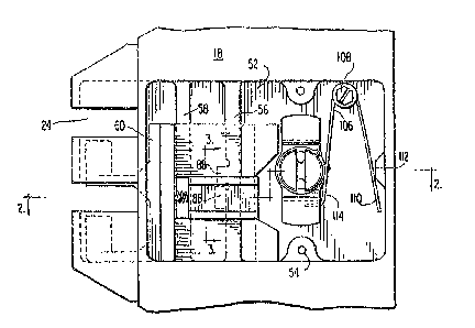
r~e ~re~errecl emi)o(liInellt o~ tIle unique mechanism
Eor~oper~ting tI~e vertical cIead-I~o1~ smooth1y and
reliaI~1y is shown in Fi3s. 1-7. ~n assemb1y arran~ement
; of the drop-kol-t strike a~l cyli~ler lock are shc~n in C~dlan
Patent application Serial No. 488,175 filed on A~l~ust 6, 1985. The
dr.op-hol~ as;eInb].y incl-~(I(s a cIrop-I~o.I.t nous~.ng I~I nav~n(3
25 : spaces 2~ eOr the reception Oe rin~s on a striker or
keeper as is kno~n i.n the art anI ;hown in the
; above~mentionecl application. With reerence to bo1t
ho~Isin(3 1~ a clel)ression ~ormin~ a~poclcet 52 has sc~ew
receivin~ I~osse~ ;~ therein ror receivin(~ the screws
~hich hc)1d the cove~ late 2r~ over the l~ack Oe the
: housinJ. ~ le rai:ls 56 an(l 5~ are in~egra1 in the
oIsin~3 ln an-.l exI:eI-l(I vert.i.ca1.1.~ a; sho~n i.n Figs. ~ and
5. r~ese 9~ e l-ai..l.S (~ e l:he I~o1~ cl~Irin~ its lockin~
and lln:Lock.ing movement.
, ~
3~
A locking bolt member 60 is shown in perspective
in Fig. S and includes `a pair of integral vertically-
extending bolt pins 62 connected to ~ main bo~y 64~
There is a vert~cal ~uide edge fi6 Qn the ~ain body which
~hen assembled in the housing 18 mates with edge 58a on
guide rail 58. The main body 64 also includes a vertical
guide rib 68 which has an edge surface 68a which mates
with surface 56a ~f the guide rail 56. A central space
70 is provided between integral parallel legs 72 of the
body 64~ Each of these legs 72 has an inside tapered tip
74 to allow operation of an actuator from the cams. The
bolt member 60 also has a spring guide post 76 for
guiding of coil spring 78.
An actuator member 80 slides in the central space
70 of the locking bolt member and includes friction-
reducing cut-outs 82 on three sides thereof, a blind hole
84 for seating spring 78 and a lug 86 which accomplishes
a locking function.
Lug 86 slides on the edg~e surface 56b of guide
rail 56 during travel~of the bolt 60 and actuator 80~
In approximately the center of the surface of the guide
rail 56 there is an integral stop 88 which during normal
vertical sliding mo~ement of the actuator member 80 will
stop such member by contacting the lug 86 as shown in
Fig. 1. In order to actuate the lock the actuator member
80 must be moved toward the strike against the bias of
. the spring 76 until the lug 86 clears the stop 88,
. compare Figs. 1 and 4.
: The actuator member 80 may be actuated by cams
operated either fr~m a cylinder lock tang 38 or the thumb-
turn 30. As shown in Fiqs. 2 and 6 the thumb-turn 30 is
attached to a thumb~turn shaft assembly 90 by a knurled
pin 91. The thumb-turn shaft assembly is formed to fit
~:
~6~3~3~
.
into a hole in housing 18 and has a slotted face 92.
cam member 94 having internally-extending tangs 96 is
slipped over the end ~f the thumb-turn shaft 90 and the
tangs are held in slot ~2. The cam .LS retained by means
of a locking ring 98 which also slips over the end o~ the
shat and is held in peripheral groove 100. The cam 94
has offset cam arms 102 which are offset Vi3 spring ledge
~04.
A torsion sprin~ 106 is secured near its middle by
a screw pin assembly 108. One leg 110 of the spring
bears against a boss 112 on the inside of the housing 18
while the other leg 114 bears against the spring ledge
104 of the cam 94. The spring 106 thus assists in
causing the thumb-turn to throw the bolt into either
locked or unlocked position and not leave it in an
intermediate position.
With re~erence to operation o~ the actuator mem~er
80 from the cylinder lock and extending tang 38, there is
a carn adaptor 116, see Fig. 7 which extends through a
hole 26a in cover plate 26. The cover plate also has
: smaller holes 26b for reception of screws. The cam
: adaptor receives the tang in one end and has a slotted
: :face t16a on the other end which is inside the hou~ing~
. A cam member 118 has a cam arm 118a and internal tangs
118b which tangs fit ints the slot 116a. A locking riny
120 fitting in groove 116b is utilized to hold the cam
118 on the cam adaptor t16. Rotating of the tang 38 will
rotate the cam arm 118a.
In operationj the cam arm 118a and cam arms 102
:can be positioned-by their rotation to contact the end of
: the actuator member 80 and force it toward the strike so
that lug 86 will clear stop 88 to throw the bolt to a
locking position, see Fig. 4. Similarly, when in locking
: position either the cam member 118 or a cam arm 102 can
~: : 35 rotate in a counterclockwise direction viewed in Fig. 4
:: . .
$~63~3~
to again move the actuator member toward the strike 16
and against the compression of the spring 78 so as to
throw the bolt to its unlockin~ position. ~ecause of the
Lntegral guide r~ils ~ui~ing the slidi.ng bolt ~nd the
actuator member sliding with the bolt the assembly is
particularly stronq, reliable and smooth operatin~.
The entire arrangement provides an extremely
strong, easy to service, smooth acting, defeat-resistant
drop-bolt lock mechanism not available with the known
prior art constructions.
'~
.
~ . '