Language selection

Search

Patent 1263110 Summary

Third-party information liability

Some of the information on this Web page has been provided by external sources. The Government of Canada is not responsible for the accuracy, reliability or currency of the information supplied by external sources. Users wishing to rely upon this information should consult directly with the source of the information. Content provided by external sources is not subject to official languages, privacy and accessibility requirements.

Claims and Abstract availability

Any discrepancies in the text and image of the Claims and Abstract are due to differing posting times. Text of the Claims and Abstract are posted:

  • At the time the application is open to public inspection;
  • At the time of issue of the patent (grant).
(12) Patent: (11) CA 1263110
(21) Application Number: 1263110
(54) English Title: REGENERATIVE HEATING SYSTEMS
(54) French Title: SYSTEMES DE CHAUFFAGE A REGENERATION
Status: Expired and beyond the Period of Reversal
Bibliographic Data
(51) International Patent Classification (IPC):
  • F28D 17/04 (2006.01)
  • F27D 17/00 (2006.01)
(72) Inventors :
  • MASTERS, JEFFERY (United Kingdom)
  • WEBB, ROGER JOHN (United Kingdom)
(73) Owners :
  • BRITISH GAS CORPORATION
(71) Applicants :
  • BRITISH GAS CORPORATION (United Kingdom)
(74) Agent: GOWLING WLG (CANADA) LLP
(74) Associate agent:
(45) Issued: 1989-11-21
(22) Filed Date: 1986-01-14
Availability of licence: N/A
Dedicated to the Public: N/A
(25) Language of filing: English

Patent Cooperation Treaty (PCT): No

(30) Application Priority Data:
Application No. Country/Territory Date
85 02760 (United Kingdom) 1985-02-04

Abstracts

English Abstract


ABSTRACT
A regenerative heating system includes at least a pair of regenerators
of the type which are operable so that while one is being heated by
waste gas the other is heating air for the combustion of fuel.
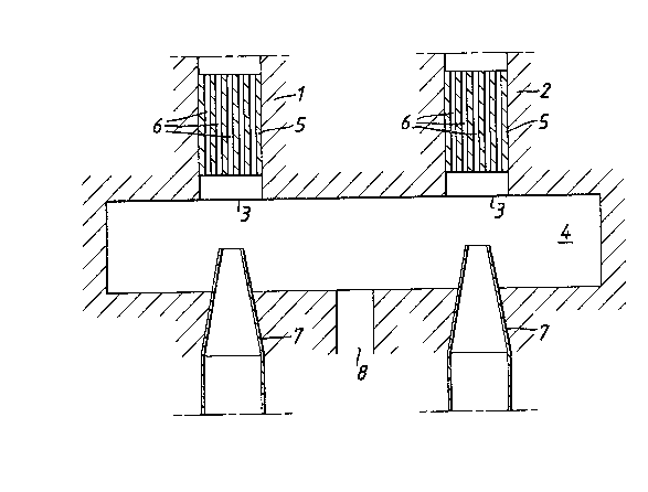
The system includes a pair of regenerators 1 and 2 which are
interconnected adjacent one end to form a chamber 4 having an outlet 8
to discharge waste gas flow into the chamber from one or other of the
regenerators. Air nozzle 7 extend into the chamber 4 to inject air
into the regenerators 1 and 2 during the air heating cycle of
regenerator. The waste gas may be removed by the suction force of a
fan or eductor.


Claims

Note: Claims are shown in the official language in which they were submitted.

CLAIMS
1. A regenerative heating system including at least one pair of
regenerators of the type which are operable so that while one is being
heated by hot gas the other is heating a cooler gas, the regenerators
being interconnected adjacent one end to form a chamber having an
outlet to discharge the hot gas flowing into the chamber from one of
the regenerators, there being for each regenerator means extending into
the chamber for injecting the cooler gas into one end of each
regenerator for heating in the regenerator before discharge through the
opposite end of the regenerator, the arrangement being such
that only one cooler gas injecting means operates at any one
time.
2. A system as claimed in claim 1 in which means are provided to
exert a suction force on the chamber outlet for withdrawal of the waste
gas through the chamber outlet.
3. A system as claimed in claim 1 in which each injection means
comprises a nozzle having an outlet end facing the one end of each
regenerator.

Description

Note: Descriptions are shown in the official language in which they were submitted.


-- 1 --
~ITLE: IMPROVEMENTS IN REGE~B~Z~E;~TINl~
The present invention relates to a regenerative heating system
including at least one pair of regenerators of the type which are
operable so that while one is being heated by waste gas the other
is heating air for the combustion of fuel.
According to the present invention we provide a regenerative
heating system including at least one pair of regenerators of the
type which are operable so that while one is being heated by hot
gas the other is heating a cooler gas, the regenerators being
interconnected adjacent one end to form a chamber having an
outlet to discharge the hot gas flowing into the chamber from one
of the regeneratGrs, the.re being for each regenerator means
extending into the chamber for injecting the cooler gas into one
end of each regenerator for heating in the regenerator before
discharge through the opposite end of the regenerator, the
arrangement being such that only one cooler gas injecting
means operates at any one time.
Preferably means are provided to exert a suction force on the
chamber outlet for withdrawal of the hot gas throu~h the chamber
outlet.
An embodiment of the invention will now be partlcularly described
with reference to the accompanying drawing which shows
schematically the lower part of a regenerative heating system
incorporating the features of the present invention. .
Referring to the drawing, the system comprises a pair of
regenerators 1 and 2, the lower ends 3 of which are connected by
a manifold 4 forming a chamber for the discharge of waste gas
from the regenerators 1 and 2.
. ~
,~ .
`
.
`' ` ` ` .. : :' ~ ,

-- 2 --
As conventional the re~enerator~ 1 and 2 compri~e ~haft3 containing a
bed 5 of permeable refractory heat ab00rbin~ ~aterial, the walls of the
regenerators al~o ~eing of refractory ~aterlal. In use, during one
cycle of operation hot ga~ eg. furnace wa~te ga~ travclllng toward~ the
beds 5 from the oppo~lte end~ (not ~ho~) of the regener~tor~ 1 and 2
pa89e3 through the b~ds by way of the channel~ 6 before dl~charge Pro~
the lower ends 3 o the regenerators 1 and 2, This cau~es the bed~ 5
to be heated. During ~he alternate cycle of operation, a cooler ga~
eg. air travelling upward~ from the lower ent~ 3 of ~he regenerator~ 1
and 2 toward~ the oppo~ite ends i8 heated by the pre-heated bed 5 a~ it
p89~e~ through the channels. It will be appreciated that wh~le waste
gas i~ heating the bed of one regenerator, air iR being hea~ed by the
bed of the other regenerator and the roles are rever~ed periodically.
Extendlng into the manifold 4 i9 a pair of air in~eceor nozzles 7 for
in~ecting air ~nto each regenera~or on alterna e cycle~. Tha air may
be supplied as convenelonal by a compressor.
Located bet~een the nozzle3 7 i9 a waste 8as outlet 8 forming a single
offtake for each regenerator. An educ~or or fan (not shown) may be
provided to draw o~f ehe waste gas produ~t~ di~harging into the
manlfold 4 fro~ the regenerator.
In u~e, whilo alr i~ belng in~ected lnto one regenerator by way of it~
nozzle, the oth~ noz~le i3 ~wltched of~. After a pre~et period, th~
other nozzle 1~ ~w~tched on and the 1rst nozzle i8 ~witched o~f.
The role~ are rever~et periodically ln t~ls m~nner whila the fan or
' :~
' :
. .

3~
eductor operates at all tlmes,
Some of the wa3te 8a~ will be entr~lned by the ln~ected air entering
the regenerator. The flnal effect of this is to reduce the flame
temperature and therefore to reduce the production of the oxldes of
nitrogen (NOX). The amount of entrained combu~tion products may be
varied and this gives a u~eful control of ~he production of NO~.
A~ conven~ional each regenerator may be provlded with a b~rner at lt~
other end by means of which fuel in~ected in~o the regenerstor can be
aàmixed with and combu~ted with the heated air be~ore dlscharge from
the regenerator. The regenerators may be conneceed to a furnace or the
like to provide combus~ed fuel therefor, the wa~te combustion produc
returning from ~he furnace to the rPgenerators.
The ln~ected air serve3 to prevent flue gas return as ~ell a~ providlng
preheated air for co~bustion of the fuel.
This sy~tem eliminates the need ~or the conventional mechanlcal
change-over valve by means of which the roles of the regenerator~ are
perlodically reversed.
The 3ystem may be u~ed a~ a recirculator whereby hot wa~te gas is~ulng
from one regio~ of a furnace i~ cau~ed to enter another region o~ the
urnace after pa~sage through the regenerator~.
..:'' "'' - ~:
. '

Representative Drawing
A single figure which represents the drawing illustrating the invention.
Administrative Status

2024-08-01:As part of the Next Generation Patents (NGP) transition, the Canadian Patents Database (CPD) now contains a more detailed Event History, which replicates the Event Log of our new back-office solution.

Please note that "Inactive:" events refers to events no longer in use in our new back-office solution.

For a clearer understanding of the status of the application/patent presented on this page, the site Disclaimer , as well as the definitions for Patent , Event History , Maintenance Fee  and Payment History  should be consulted.

Event History

Description Date
Inactive: IPC from MCD 2006-03-11
Time Limit for Reversal Expired 2005-11-21
Letter Sent 2004-11-22
Grant by Issuance 1989-11-21

Abandonment History

There is no abandonment history.

Fee History

Fee Type Anniversary Year Due Date Paid Date
MF (category 1, 8th anniv.) - standard 1997-11-21 1997-10-14
MF (category 1, 9th anniv.) - standard 1998-11-23 1998-10-13
MF (category 1, 10th anniv.) - standard 1999-11-22 1999-10-13
MF (category 1, 11th anniv.) - standard 2000-11-21 2000-10-11
MF (category 1, 12th anniv.) - standard 2001-11-21 2001-10-15
MF (category 1, 13th anniv.) - standard 2002-11-21 2002-10-15
MF (category 1, 14th anniv.) - standard 2003-11-21 2003-10-15
Owners on Record

Note: Records showing the ownership history in alphabetical order.

Current Owners on Record
BRITISH GAS CORPORATION
Past Owners on Record
JEFFERY MASTERS
ROGER JOHN WEBB
Past Owners that do not appear in the "Owners on Record" listing will appear in other documentation within the application.
Documents

To view selected files, please enter reCAPTCHA code :


To view images, click a link in the Document Description column. To download the documents, select one or more checkboxes in the first column and then click the "Download Selected in PDF format (Zip Archive)" or the "Download Selected as Single PDF" button.

List of published and non-published patent-specific documents on the CPD .

If you have any difficulty accessing content, you can call the Client Service Centre at 1-866-997-1936 or send them an e-mail at CIPO Client Service Centre.


Document
Description 
Date
(yyyy-mm-dd) 
Number of pages   Size of Image (KB) 
Claims 1993-10-06 1 22
Abstract 1993-10-06 1 15
Drawings 1993-10-06 1 26
Descriptions 1993-10-06 3 104
Representative drawing 2001-06-26 1 21
Maintenance Fee Notice 2005-01-16 1 173
Fees 1996-10-14 1 50
Fees 1995-10-10 1 49
Fees 1994-10-12 1 182
Fees 1993-10-13 1 173
Fees 1992-10-14 1 55
Fees 1991-10-14 2 98