Note: Descriptions are shown in the official language in which they were submitted.
~ 2$~3rj~o
This invention relates to optical waveguides.
Optical waveguides operate to transmit electromagnetic energy of
wavelengths in or near the visible spectrum (i.e. in the form of light) and
comprise an inner core of transparent material surrounded by a cladding hav-
ing a lower refractive index than the core and which acts to prevent light
escaping from the core. It is important that attenuation in the core is
minimized and to this end various different materials have been proposed
for the core and the cladding.
According to the invention an optical waveguide comprises a core
of glass formed of phosphorus pentoxide and silica and a cladding ~f a glass
of lower refractive index than the core wherein the decrease in refractive
index of the cladding relative to the core is obtained at least in part by
having a lower or zero concentration of phosphorus pentoxide in the cladding
than in the core.
The cladding may comprise pure silica~a high silica content glass
or silica containing a proportion of phosphorus pentoxide which is lower
than the concentration of the phosphorus pentoxide in the core.
Instead of using pure silica for the cladding, or a phosphosilicate
glass having a lower concentration of phosphorus pentoxide than the core, a
borosilicate glass can be used as the cladding.
In accordance with another aspect of the invention there is provid~
ed an optical waveguide comprising a glass formed of phosphorus pentoxide
and silica wherein there is a graded change of refractive index in a radial
direction said graded change of refractive index being caused by a correspond-
ing graded change in concentration of phosphorus pentoxide.
According to another aspect of the invention there is provided an
optical waveguide comprising a core of glass formed of phosphorus pentoxide,
germania and silica and a cladding of a glass of a lower refractive index
than the core~
i3S~C~
- In addition to phospllorus pentoxide which is included in the core
an additional component may be added, for example germania, or a trivalent
oxide which may be selected from the oxides of boron, aluminium and antimony~
In accordance with a further aspect of the invention ~ method of
manufacturing an optical waveguide includes the steps of passing a mixture of
- la -
12~3~SC~
vapours o-f suitable compounds of phosphorus and silicon through a tube,
heating the tube to oxidize the said compounds to phosphorus pen~oxide and
silica and fusing the phosphorus pentoxide and silica on the interior surface
of the tube.
In order to reduce the deleterious effect of impurities in the
glass it is desirable for the starting compounds to be in liquid form so that
they can be readily purified for example by distillation. Suitable compounds
comprise silicon tetrachloride and phosphorus trichloride or phosphorus
oxychloride. Oxygen is bubbled through the two liquids and the oxygen streams
carrying silica tetrachloride vapour and phosphorus oxychloride vapour are
then mixed and more oxygen may be added in such a ratio as to give the desired
relative concentrations of phosphorus pentoxide and silica in the glass. The
mixed vapour is then oxidized at an appropriate elevated temperature and
simultaneously deposited as a Fused layer of phosphosilicate glass on the
interior surface of a silica tube.
The coated tube is then collapsed to form a rod and the rod is then
drawn down to a fibre.
According to another aspect of the invention there is provided a
rod preform for an optical waveguide comprising a core of a glass formed of
phosphorus pentoxide and silica and a cladding of a glass of lower refractive
index than the core wherein the decrease in refractive index of the cladding
relative to the core is obtained at least in part by having a lower concentra~
tion of phosphorus pentoxide in the cladding than in the`core.
According to still another aspect of the invention there is pro-
vided a rod preform for an optical waveguide comprising a glass formed of
phosphorus pentoxide and silica wherein there is a graded change of refrac-
tive index in a radial direction, said graded change of refractive index being
caused by a corresponding graded change in concentration of phosphorus pent-
oxide.
In order that the invention may~be more fully understood reference
~ 2 ~
12~'3~;~0
will now be made to the accompanying drawings in which:-
Figure 1 ilLustrates apparatus used for manufacturing an opticalwaveguide embodying the invention~ and
Figure 2 illustrates an optical waveguide that is produced.
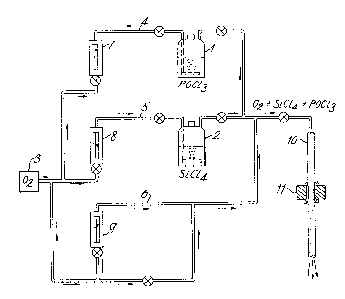
Referring now to Figure 1 there is shown therein apparatus for the
chemical vapour deposition of appropriate materials in a silica tube. The
starting materials for the deposition process are volatile compounds of the
required constituents. Conveniently phosphorus oxychloride and silicon
tetrachloride are used and these are contained in the vessels 1 and 2. IE
the cladding incorporates a borosilicate glass then a similar additional
vessel containing boron trichloride is also provided. The phosphorus oxychlor-
ide in vessel 1 can be distilled in order to improve its purity. Oxygen
Erom a supply 3 is passed through respective lines 4, 5 and 6 at a rate which
is controlled by flow meters 7~ 8 and 9 in these lines. The oxygen in passing
through vessels 1 and 2 carries with it vapours of phosphorus oxychloride
and silicon tetrachloride respectively and the two vapour streams are combined
and if required are diluted with further oxygen from line 6 to pass through a
glass deposition tube 10. A short furnace 11 is moved relatively to tube 10
and oxidation of the chlorides to produce .he relevant oxides takes place.
Alternatively furnace 11 may be fixed and silica tube 10 traversed through
the furnace.
~Z~355~
The oxidation reaction of the chlorides of silicon and phosphorus
occurs spontaneously in the gas phase at the relatively low tempera-tur3
of approximately 1300 C to form a dense fog of small glass particles.
In additionl provided the viscosity of the glass is substantially
lowered by the incorpora-tion of sufficient phosphorus pentoxide (or
other suitable component) then the glass particles fuse on the walls
of the container to form a clear, uniform, homogeneous layer of
phosphosilicate glass. Thus a high deposition rate can be obtained
since no gas dilutants are required to slow the reaction and the
glass deposition may occur directly on the walls of the silicn tube
which, because of the comparatively low temperature, suffers no
deformation.
Typical operating conditions are as follows. For a silica tube
with a bore of lOmm the flow rates of oxygen and silicon tetra-
chloride vapour are kept constant at 60o and 35 ml/min. respectively,
while that of phosphorus oxychloride vapour is varied over the
range 1 to 13 ml/min. With a furnace temperature between 1250 C
and 1550 C the phosphosilicate glass layer is deposited on the
inner wall as the tube is passed through.
Tube 10 is traversed a number of times through furnace 11 and
on each traverse a layer of glass is deposited on the inner surface
of tube 10. The proportions of the constituents are varied after
appropriate number of layers are deposited in order to produce the
required glass for the cladding and the core as may be required.
For a graded index optical waveguide there will be a gradual change
in proportion of constituents between appropriate layers.
3~
The deposition time of each layer is about 8 minutes for a
typical length of tube 10 of 50 cm and the phosphorus pentoxide
concentration is between ~% and ~0% by weight depending on the
flow rate of the phosphorus oxychloride. With these flow rates
and temperature the amount of downstream soot formation which
passes out of the far end of tube 10 is small. The refractive
index of successive layers each about 12 microns thick can be
accurately controlled and a wide rcange of profiles from a uniform
to a graded index can be produced.
To form A cladding of a borosilicate glass apparatus similar
to that shown in Figure 1 is used but with an additional input for
boron trichloride gas. The flow rates of boron trichloride and
silicon tetrachloride are typically 8 and 35 ml/min,respectively
together with ~50 ml/min of oxygen. The first three layers are of
constant composition while the next three are formed by reducing
the flo~ rate of boron trichloride to zero in stages. The amount
of phosphorus oxychloride is then increased gradually from zero
to 9 ml per minute over the next 1~ layers thus giving a total of
20 layers. While in the initial tube so formed the successive
depositions of phosphosilicate glass are cleariy differentiated a
certain amount of diffusion takes place during the subsequent tube-
collapsing and fibre-drawing stages to smooth out the concentration
gradient. A fibre having a graded index core in a borosilicate
cladding is thereby produced.
Collapse of the layered supporting tube 10 into a rod preform
is effected by rotating tube lOand heating it carefully in an
~2f~3~;S~
oxy-hydrogen fLame which is traversed along the length of the tube
and which heats the tube to a sufficiently high temperature to cause
its collapse.
When collapsing the tube it is important to maintain its
circularity since any departure therefrom will affect the circularity
of the final drawn fibre and hence adversely affect its optical
transmission properties. To Inaintain the circularity of the
collapsing tube a small excess pressure is maintained within the tube
as it is collapsed. The magnitude of this pressure is a function of
the diameter of the central hole. In addition to maintain circularity
nfter the central bore is closed a cooling æone is passed along the
collapsed tube immediately behind the heating zone.
The tube can conveniently be pressurised by venting a gas flow
to air through a restric-ted orifice. The gas flow can comprise
the original reactants, namely oxygen carrying silicon tetrachloride
and phosphorus oxychloride vapours. A flow high in phosphorus
oxychloride prevents loss of the more volatile phosphorus pextoxide.
One end of the tube is connected to the input side of the orifice
and the other end is sealed. This method has the advantage that
the internal pressure will not change significantly when the gas
in the tube is heated and expands. The heating zone is traversed
along the tube at an appropriate rate from the sealed end. The
cooling zone comprises an array of nozzles positioned immediately
behind the gas burner and fed with air under pressure to direct
2S an air blast on to the heated collapsed tube. Control of the air
blast gives some control over the collapse of the tube ~nd the
l;~fi355C)
blast can be con~eniently adjusted to make the point of collapse
occur very close to the chill air blast region. By this means
the effect of internal pressurisation can be obtained until the
last possible moment, when the central hole disappears and -the
glass is immediately chilled while it still has a perfect circular
form. The heating and cooling zones may be traversed along the
tube several times to collapse it in stages.
An alternative method of collapsing the tube is to pass it
through a heated die. Tho size of the die may be such that the
bore of the tube is completely closed to form a rod, or may be
chosen to leave a small hole in the centre of the tubeA The hole
is eliminated during tbe fibre pulling operation. Another method
of collapsing the tube is to pass a hot zone along the tube and rotate
it while applying a graphite tool against its side and moving the
tool slowly along the tube behind the hot ~one.
After a rod has been formed from the collapsed tube it is then
drawn down into a fibre in a fibre drawing machine. A 50 cm rod
obtained from a tube 10 of corresponding length can be drawn out to
form a 1.2 km length of fibre.
~O The addition of phosphorus pentoxide to silica has a marked
effect on certain physical properties of the resulting phosphosilicata
glass which limits the proportion of phosphorus pentoxide that can be
included, although as a high a proportion as possible is desirable to
obtain the requisite optical properties. One physical property that
is affected is the expansion coafficient. The expansion coefficient
of pure silica is much lower than that for phosphorus pentoxide so
~LZfi35~0
that as the proportion of phosphorus pentoxide in a phosphosilicate
glass is increased there is a corresponding increase in the
expansion coeffici~n~ and an increasing mismatch between the silica
cladding and the phosphosilicate core. In conjunction with the
somewhat lower strength of phosphosilicate glass this can result
in spontaneous shattering of the core if the proportion of
phosphorus pentoxide is too high. 0-ther physical properties that
are affected are the viscosity and the volatiiity which create
problems of manufacture of an optical waveguide.
To improve the physical matching of the core and cladding
an fldditional component comprising germania, *-itan~a or a
trivalent oxide selected from one or more of the oxides of boron,
aluminium, antimony, arsenic and bismuth can be incorporated.
The additional componet may be incorporated into the glass
core by adding the vapour of a volatile compound of the selected
element to a gaseous stream carrying the vapour of appropriate
volatile compounds of silicon and of phosphorus and depositing
the vapour on the inner surface of a silica tube as described in
above.
Alternatively a layer of a two-component phosphosilicate glass
can be formed on tha inner surface of a hollow tube as described
above and the third component diffused at elevated temperature into
the layer from within the tube. The diffusion source may be either
a vapour, a liquid or a solid and the difusion step can be
completed either before collapsing the tube or after partial collapse
so as to leave a small hole in the centre. A separate diffusion
~2~35S~1
stage may bs necessary in cases where the tube is subjected to a
high temperature, or alternatively the diffusion may take place
after collapsing the tube and when drawing it into fibre form when
the high temperature and resulting low viscosity may be sufficient
to allow simultaenous drawing and diffusion.
An example of a typical fibre manufactured by the method
described above is shown in Figure 2 in cross-section. The fibre
has A central core 31 formed of phosphosilicate glass and if there
has been a progressive change in the rate of oxygen bubbled through
the phosphorus oxychloride vessel 1 then the core 31 will have a
graded refractive index. Surrounding core 31 is a cladding 32 of
borosilicate glass. The outermost annular ring 33 is formed from
the original silica su,pport tube 10 and plays no part in the
optical properties of ';he fibre but acts as a mechanical support
and protection. Measurements of the attenuation of optical fibres
of the kind shown in Figure 3 show that over a wavelength from 0.75
to 1.25 microns the loss is as low as 3dB/km and is constant over that
range~ The hydroxyl impurity content in the fibre is extremely low
due it is believed to the strong hygroscopic nature of phosphorus
pentoxide. Thus any residual water in the depositing equipment is
converted on contact to non-volatilè phosphoric acid and is not
carried into the deposition zone.