Note: Descriptions are shown in the official language in which they were submitted.
3~
BACKGROUND OF THE INVENTION
This invention relates to the detection of DC ground
faults. In particular it relates to an apparatus and a method
for detecting such faults in normally ungrounded DC distribution
systems having significant capacitive reactance components and
strong electromagnetic and electrostatic fields associated with
utility power generation and distribution, industrial plants, and
computer/electronic systems, where ground faults must be located
without taking unaffected equipment out of service.
A basic problem in such systems is the need to identify
small DC fault currents namely low to high impedance ground
faults in the presence of much larger DC load currents.
One well-known ground detection circuit consists of a
center tapped high resistance connected across the DC source and
an indicating milliammeter between the center tap and ground. A
ground fault anywhere on the DC system causes an indication on
the milliammeter. Since the high resistance limits the ground
fault current to a few milliamperes the circuit is not tripped
off when a fault occurs. This is important since loss of power
~'~
7(i~;
O- d typical DC control circuit is often critical and could
involve safety hazards. It is important to locate and repair any
ground faults as soon as practical since a second ground fault
would trip the circuit.
Such a ground detection system while indicating that a
ground fault has occurred does not tell where the fault lies. It
could be in any one of many pieces of equipment on numerous
brar.ch circuits. Again because of the critical nature of these
circuits it is not practical to turn them off one at a time to
locate the fault. Thus a system is needed to locate the Eaulty
equipment without interrupting these critical circuits.
Another system fo. DC fault detection requires the
introduction into a DC fault line of an AC current at a frequency
of about 25 Hz, which is then detected. A problem with the
introduction of such AC current is that it is liable to cause
operational problems, mask some faults, and create complications
in detecting and localizing ground faults in some DC loads in the
system.
It is also known elsewhere to test for DC faults in
small systems employing grounded 12-volt battery type power
supplies in automobiles and the like. Such grounded DC systems
require the connection of an injector across terminals of the
battery supply and thereafter a detector is applied over the
wiring system with sound detection means such that an increasing
sound would indicate where a DC fault exists.
Such systems operate in response to high DC fault
currents in an environment where there is no capacitive or
inductive reactives of consequence, where there is of no real
concern and where the DC system is effectively shut off when the
fault detection is being made.
--2--
7C~;
It is also known in AC systems to detect ground leakage
by a relay which interrupts the system so as to introduce a fault
current in the sense of a pulsating input, Such systems ho~ever
are of a nature that a D'Arsonval type meter or permar.ent magnet
moving coil meter are used for detection of the pulsating
input. Such a meter requires a current transformer suitable for
detecting relatively large AC fault currents, and this is
unsuitable for measuring pulsating DC fault currents of a lower
value. These detection systems are particularly unsuitable in
high electrostatic and electromagnetic environments.
SUMMARY OF THE INVENTION
According to the invention there is provided apparatus
for the detection of ground leakage in a normally ungrounded DC
distribution system which includes a DC power supply and
conductors from the supply for supplying power to load means
connected to the DC distribution system~ There is a tapping
point between resistor means connected across the DC power supply
and a responsive means, such as indicator means, connected
between the tapping point and a ground point, such that a ground
leakage in the system completes a circuit to activate the
responsive means. With such ground leakage activation, there are
means adapted to interrupt periodically the circuit to
effectively generate an interrupted ground fault signal. Such
signal is detected by either a permanently located and/or
portable sensor or means located relative to the DC system such
that a pulse interrupted ground signal can be detected by the
sensor means and thereby the ground fault located in the DC
system.
$
The sensor means includes means to suppress noise
introduced into the pulse signal by the periodic interruption of
the circuit during the ground fault occurrence, and also includes
means to eliminate the effects of distributed capacitive and
inductive reactance.
BRIEF DESCRIPTION OF THE DRAWINGS
Eigure 1 is a block diagram illustrating a DC system
with various loads, and in which a ground Eault is present in one
of the loads, including sensor means for sensing such fault.
Figure 2 is a block diagram schematic of the sensor
means for detecting interrupted ground fault signals.
Figure 3 is a detailed schematic of the sensor means of
Figure 2.
Figure 4 is second block diagram schematic of the sensor
means for detecting interrupted ground fault signals.
Figures 5A and 5B are detailed schematics of the sensor
means of Figure 4.
DETAILED DESCRIPTION OE THE DRAWINGS
.
Apparatus for the detection of ground leakage in a
normally ungrounded DC system (Figure 1) comprises a DC power
battery supply 10. Main bus bars 11 and 12 from the battery
supply 10 supply power to different loads 13, 14 and 15 in this
exemplary embodiment. Conductors 13a and 13b from main bus bars
11 and 12 connect with load 13. Similarly, the main bus bars 11
and 12 are connected to load 14 through conductors 14a and 14b,
there are conductors 15a and 15b to load 15.
-4
f ~? ~
Across the bus bars or conductors 11 and 12 are
resistors 16 and 17 and between these resistors 16 and 17 is a
tapping point 18. A responsive element in the form of ground
indicator meter 19 is connected between the tapping point 18 and
a ground point 20 such that a ground fault leakage in the system
closes a ground circuit to activate the indicator meter 19. In
the conductor 21 connecting the indicator means 19 to a ground
point 20 there is located a reed relay 122 operable by a pulser
22 to open and close the relay 122 at approximately one cyc~ e
every 6 seconds. In this fashion a DC pulsing fault current is
generat.ed into the ground circuit and thereby an interrupted
ground fault signal is obtained.
The remainder of the ground circuit is constituted
through the bus bars 11 and 12 and conductors 14a and 14b to load
14 which is indicated to have a ground fault 23. In the
exemplary embodiment loads 13 and 15 do not have such ground
fault.
The relay 122 is normally closed. The pulser 22 is
incorporated in a circuit with a normally open switch 222 for
selectively activating said pulser 22 to operate said relay
122. Closure of switch 222 can be manually effected or be by
electromechanical means on the occurrence of a ground fault
condition.
In the one example of the invention, for each load
circuit 13, 14 and 15 there is provided a sensor 24
respectively. Such sensor 24 includes a Hall effect sensing
element 25 together with detection circuit 125 to indicate
whether a pulsating ground signal is sensed by the Hall effect
X5
element ~4 in a particular conducting line 13a, 13b, 14a, 14b,
15a or 15b respectively.
5--
~ 7~
The pulser 22 is not placed into circuit until such time
as the ground fault indicator 19 detects the existence of a
ground fault current in the embodi.~ent described. In some cases,
however, the indicator 19 may be dispensed with, or the pulser 22
continually applied irrespective of the indicator 19 such that
any permanently located sensor 24 will indicate a fault current.
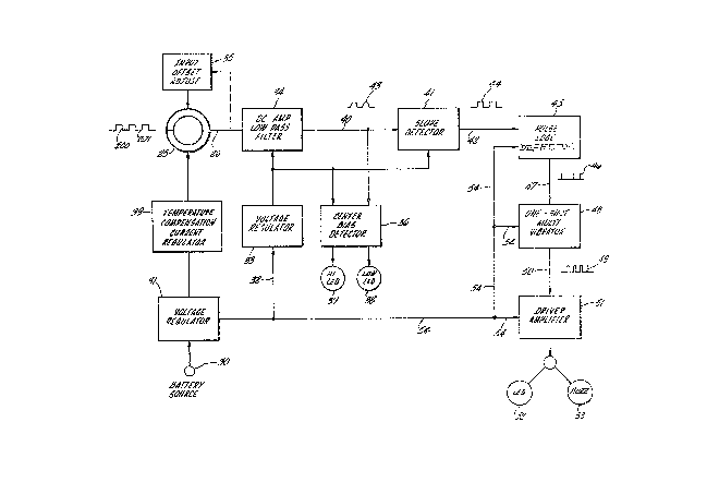
The embodiment of Figures 2 and 3 is now described.
The sensor 24 for detecting interrupted ground fault
signals as illustrated in block diagram of Figure 2, includes a
Hall effect sensing element 25 which receives both a composite
pulse signal 200 with superimposed noise 201 of which is fed from
the ~all effect sensor 25 along conductor 26. The signal is
received from the pulser 22 in the form of a one-sixth (1/6) to
one-eleventh (1/11) Hertz square wave 200. Accordingly the
period is in the range of 6 to 11 seconds
The power supply to the sensor 24 includes a battery
source 30 which is normally a small DC volt supply. This supply
30 is passed through a first voltage regulator 31 which detects
variations of the battery supply, for instance~ a decrease of the
battery voltage over a time period. The battery voltage sample
is passed along line 32 to a second voltage regulator 33.
The first voltage regulator 31 stabilizes the battery
voltage supply to the overall circuit and makes it possible for
the circuit to operate from 6.5 volts to 15 volts. The second
voltage regulator 33 delivers a very stable voltage supply to a
DC amplifier and low pass filter 34. Combined with the voltage
regulator 31 the voltage regulation is within + 0.02~ and this
eliminates the spurious injection of transients to the DC
amplifier 34.
~ 7 ~
The DC amplifier and low pass filter 34 amplify the
signal transmitted along conductor 26 from the Hall effect sensor
25 and passes only those frequencies that are 5 Hertz or less.
For proper operation, the output voltage range of the DC
amplifier is within 0.75 volts to 2.75 volts.
Associated with the Hall effect sensor 25 is an input
offset adjustment element 35 which permits for the manual
adjustment to bring the output level of the Hall effect sensor 25
to a value suitable for operation of the DC amplifier 34.
In order to ensure that the DC amplifier output voltage
is in the appropriate range there is provided a center biased
detector 36 with visual indicator means 37 and 38 respectively
indicating whether the DC amplifier is set to operate in its
proper range. With the visual indicator 37, namely, the hi-LED
lit-up there is indicated that the DC amplifier output is greater
than 2.75 volts. With the indicator 38, namely, the "low-LED"
lit-up there is indicated that the DC amplifier 34 output is less
than 0.75 volts. Thus, when both the indicators 37 and 38 are in
the "off" state the DC amplifier 34 is correctly set up.
Also located between the voltage regulator 31 and Hall
effect sensing element 25 is a temperature compensating current
regulator 39 which provides a constant 20 mA current to the Hall
effect sensor 25 for control of the current requirements.
The output from the DC amplifier and low pass filter 34
is passed along conductor 40 to a slope detector 41. The output
from the detector along line 42 changes from a high to low or low
to high state when the output wave form 43 from the DC amplifier
low pass filter 34 changes at a rate of 5mV per second or more
from the point of inflection of the wave form curve.
7(~
The pulse type square wave output 44 from the slope
detector 41 is fed by conductor 42 to a pulse edge detector 45.
The detector 45 outputs along line 47 a positive spike 46 for
every rise or fall edge of the slope detector output wave ~orm
44. The output spike wave form 46 which is fed along conductor
47 to a one shot multivibrator 48 which outputs a 0.6 second
duration pulse, for every pulse from the pulse edge detector
45. The one-shot multivibrator 48 outputs this pulse 49 along
the output conductor 50 which ~eeds a driver amplifier 51. The
amplifier 51 operates either an LED indicator 52 or buzzer 53 to
provide a visual or audio means of recognizing the existence of a
fault.
The voltage regulator 31 is also connected along line 54
with the driver amplifier 51, the one-shot multivibrator 48 and
the pulse edge detector 45. Alternatively, to a LED 52 or buzzer
53 there can be a meter 55 operated by the driver amplifier 51 as
indicated in Figure 1.
Figure 3 discloses in more detail the circuitry
constituting the sensor illustrated in the block diagram of
Figure 2. The whole sensor device 25 is shown connected through
conductor 26 via an input offset adjust constituted by a variable
resistor bank 55 to the IC elements 56 and 57 output of which is
in turn connected with the IC 58 to constitute an amplifier and a
low pass filter.
The voltage regulator 33 is connected to the amplifiers
by line 59 and to the center bias detector 36 along line 60 and
to the slope detector by line 61.
The voltage regulator 33 consists of several transistor
configurations 62, 63, and 64 arranged in voltage regulating
fashion.
~ ~ 37 ~i
The voltage regulator 31 includes a capacitorJ64, the
positive side of ~hich is connected through line 65 with the
temperature compensating current regulator which includes an
array of transistor 66 and 67 and diode 68 suitable arranged.
The output of the current regulator 39 is connected by
conductors 69 and 70 to the Hall effect sensing device 25.
setween the battery 30 and the voltage regulator 31 is a
manually operable switch 71 to activate the sensor 24 as desired.
The center bias detector 36 includes a pair of IC
elements 72 and 73 respectively, the outputs of which are
connected to transistors 74 and 75 respectively to in turn drive
the L~D's 37 and 38.
The slope detector 41 receives a signal from the DC
amplifier and low pass filter along the conductors 40 which is
then passed through a first IC element 76 and the output in turn
to an IC element 77. The output from IC 77 passes along line 78
to the pulse edge detector 45 and multivibrator 48 along line
78. The pulse edge detector and multivibrator are constituted by
the array of transistors 79, 80, and 81 suitable arranged. The
output from the multivibrator transistor 81 passes along line 50
to the driver amplifier circuit constituted by a transistor 82
which itself is arranged to drive either the buzzer 53 or L~D s2
as necessary.
The embodiments of Figures 4, 5A and 5B are now
discussed.
The sensor 324 for detecting interrupted ground fault
signals as illustrated in block diagram of Figure 4, includes a
Hall effect sensing element 325 which receives both a composite
pulse signal 300 with superimposed noise 301 of which is fed from
the Hall effect sensing element 325 along conductor 326.
3 ~ 3~ fi
The output from the DC amplifier and low pass filter 339
is passed along conductor 340 to an instrument ampliEier and low
pass filter 341, device 341 transforms the differential input
signal to an imbalance output signal.
The square wave output pulse 303 from the instrument
amplifier 341 is fed by conductor 342 to operational amplifier
and low pass filter 343. The output of operational amplifier 343
along line 344 is a square wave signal. The output waveform 304
is fed along conductor 344 to amplifier circuit 345, 346 and
switch relay 350. The amplifier circuit 345 operates the
positive LED and negative LED to provide a visual indication of
what line has a ground fault current. The output signal 304
along conductor 344 is fed to amplifier 346, who controls the
green LED indicator. The output signal 304 along conductor 344
is fed to the relay switch 350; the input of relay 350 is
controlled by line 352 who received a synchronization signal 361
from interruptor circuit 322; the output signal of relay switch
350 is fed along conductor 351 to track and hold circuit 352; the
~-,output signal of track and hold circuit 352 is fed into line~ 353
to operational amplifier inverting circuit 354; the output signal
of circuit 354 is fed to line 355 and to the input of 356.
Amplifier circuit 356 receives a signal from Hall effect
generator 325 via conductor 326, amplifier circuit 356 has an
adjust element who controls the DC current to be applied to the
Hall effect generator driver circuit 357. The H.E.G. DC driver
circuit receives the composite signal from circuit 356 and the
control signal is applied to H.E.G. 325 by means of conductor
359.
The signal is received from the pulser 322 in the form
of a one-eleventh (1/11) hertz square wave 300.
--10--
~ ~ 37 ~A,5
The power supply (358) ~, is a +5, -5 volts DC
regulated power source, this power supply has an over-voltage,
over-current protection circuit to supply power to the sensor and
amplifier circuits.
The DC amplifier and low pass filter 3~9 amplifiet the
signal transmitted along conductor 326 from the Hall affect
sensor 325 and passes only those signals that are 10Hz or less.
For proper operation, the output voltage range of the DC
amplifier shall be within and + (plus) or - (minus) 200 milivolts
in order to ensure that the DC amplifier output voltage is in the
approp~:iate range. An adjustment element, 336, is provided with
visual indicators, 347, 348, and 360, respectively, indicating
whether the DC amplifier is set to operate in its proper range.
With the visual indicator 347, namely the positive LED
illumina~ed, indicates that the DC amplifier output is greater, +
(plus) by 200 microvolts. With the visual indicator 348, namely,
the negative LED illuminated, this indicates that the DC output
of amplifier 339 is less - (minus) by ~00 microvolts, thus, when
both indicators 347 and 348 are in the OFF position and indicator
360 green LED is illuminated, the DC amplifier 339 is correctly
aligned.
Associated with the Hall generator is an adjustment
element 356 which permits the manual adjustment of a constant
current to bring the output level of the Hall effect sensor 325
to a value suitable for operation of DC amplifier 339.
Figures 5A and 5L disclose in more detail the circuitry
constituting the sensor illustrated in the block diagram of
Figure 4. The whole sensor device is shown connected through
conductor 326 to differential amplifier U4; the differential
ou~put of U4 is connected through conductor 340 to the differen-
~.~$~7C~i
tl input of Ul; the unbalance output signal of Ul is connectedvia conductor 342 to the operational amplifier and low pass
filter S6; the output of S6 is applied via conductor 344 to
amplifier integrated circuit S8 and S9; S8 will control t~e red
positive and red negative LED 347 and 348; S9 will control the
green LED 360. Conductor 344 feeds switch relay 350 which opens
and closes with the synchronization signal 361 from the
interruptor circuit 322 via conductor 362; the output signal of
switch 350 is fed via conductor ~51 to track and hold circuit
352; IC element S5, the output from IC S5 passes along line 353
to the inverted circuit 354; this inverted circuit consist of IC
S4 and associate resistor and capacitors. The automatic gain
control circuit 356 receives the signal from inverter circuit 354
via conductor 355 which will feed back signal from the Hall
effect generator 325 via conductor 326, this composite signal is
fed to IC S3 via conductor 327 to transistor Ql via conductor 359
which controls the current applied to Hall effect generator 325.
- In operation of the DC fault detector the procedure is
that the fault is first verified as existing in the system by
observing the indicator 19 located between the tapping point 18
and ground 20 or permanent alarm system or di~ferential volt
meter. This would indicate that a fault exists and should this
be sufficiently large then a resistive fault current would be
indicated. The pulser 22 is then turned on by closing the switch
2Z2.
The Hall clamp-on sensing devices 24 as currently
available are sensitive to a fault current of at least 3
milliamps. More sensitive devices, however, could be available.
The sensing elements 25 are clamped over the conductors
13A, 13B, 14A, 14B, 15A and 15B respectively, optionally, after
-12-
fi
ve fying with the percent ground meter l9 that the fault current
is sufficiently large enough to detect. Thereupon the input
offset adjust 35, and in the embodiment of Figures 2 and 3,
center bias detector 36 are adjusted so as to effectively render
the sensor 24 operational.
The isolation of the detector fault current to the
branch circuit 13A, 13B, or 14A, 14B~ or 15A, lSB is determined
by a response to the pulsed input signal by either the LED 52,
buzzer 53, meter 55, or LED347 or 48 which constitutes the
indicator means of the sensor 24 in the respective branch having
a ground fault.
In the example illustrated the response will be in the
branch line 14A, 14B in view of the ground fault 23. The sensor
24 will in that circuit pass interrupted ground fault current as
generated by the pulser 22 through the reed relay 122 which is
opened and closed in the ground circuit. Accordingly, the
indicator in the sensor 24 will respond. In those circuits where
there is no ground fault there will be no indicator response or
an irregular response in the sensor 24. In the embodiments of
Figure 4, 5A and 5B there will be a green LED~60 response in the
sensor 24. The indicator response in sensor 24 for a resistor
fault output would be regularly indicated at about 3 second
intervals. In the embodiment of Figures 4, 5A and 5B there will
be a red LED347 and348 response.
In some cases, by moving the sensor 24 along the
conductors 14A and 14B to a point where the ground fault signal
ceases to be detected by the sensor it has provided a means for
detecting the actual location of the ground fault. The detector
in fact need be placed only about either conductor 14A or 14B to
locate more precisely the location of the fault.
-13-
Embodiments of th~ invention sensors can be permanently
located at discrete points. ~oreover, a pulser can also
permanently be in circuit such that on the occurrence of a ground
fault one or more sensors will respond enabling the location of
the ground fault. Essentially, the apparatus and method of the
invention ensure that the normally ungrounded DC system can
remain operational in respect of the ungrounded loads and this
prevents expensive and unnecessary down time for systems which
must continue operation while others suffer ground fault problems
and during detection of those problems.
Many changes and variations may be made in the appa~atus
and method providing widely different embodiments in
applications for this invention without departing from the scope
thereof. All matter contained in the above description as shown
in the accompanying drawings shall be interrupted as illustrating
but not limiting, the invention being interpreted solely by the
scope of the appended claims.