Note: Descriptions are shown in the official language in which they were submitted.
12~377~
1 50,731
ELEVATOR SYSTEM
BACKGROUND OF THE INVENTION
Field of the Invention
T~a invention relates in general to elevator
systems, and more specifically to elevator systems having a
plurality of elevator cars under group supervisory control
by a system processor or dispatching function.
Description of the Prior Art: .
In a typical elevator system having a plurality
of elevator cars under group supervisory control, all hall
calls are normally treated alike from a priority view
point, unless they are from a special pre-defined floor,
such as a lobby floor, a convention floor, or the like; or,
the call has been registered beyond a predetermined period
of time, i.e., a timed-out call. It is sometimes desirable
to provide immediate priority service for a hall call by
providing a riser of hall call pushbuttons which are
independent of the normal hall call pushbuttons. The
pushbuttons of the independent riser are placed in an
inconspicuous location; thus, the term "inconspicuous
riser" or IR. Calls registered on the inconspicuous riser
are ignored by the dispatcher function unless the IR
feature is activated, such as by a switch in the traffic
director's station (TDS~. When the IR switch is moved to
the "activated" position, a predetermined car, or cars, is
removed from group control as soon as it serves any car
calls it may already have registered. This IR car will
12fi3773
2 50,731
then respond only to hall calls placed on the IR riser, for
as long as the IR feature is selected, with a separate
dispatcher function handling the IR calls. The hall
lanterns are not activated by IR cars serving IR calls.
Since the addition of a second dispatcher adds substantial-
ly to the cost of implementing the IR feature, it would be
desirable to be able to handle an IR riser with the same
dispatching function that handles the normal hall call
riser, if this result can be achieved without degradation
of elevator service to hall calls registered on the perma-
nently enabled riser.
SUMMARY OE THE INVENTION
Briefly, the present invention is an elevator
system having a plura~ity of elevator cars mounted in a
building, with each car being controlled by an associated
car controller, and further including first and second
independent risers of hall call pushbuttons. The first
riser, which is the normal riser, is always enabled. The
first riser handles front door hall calls, and if the car
has a rear door, it will also handle rear door hall calls.
The second riser, which is an inconspicuous riser (IR~, is
selectively enabled, such as by a switch. When the second
riser is enabled, one or more elevator cars are selected
for exclusive second riser service. The car controllers of
the elevator cars define the building configuration for a
supervisory processor or dispatching function, with each
car controller supplying the supervisory processor with its
own set of enables which set forth the floors of the
building that the associated elevator car is enabled to
serve. A single dispatching function serves both the first
and second independent risers by having the car controller
of each car activated for exclusive second riser service
indicate that it is enabled for fictitious floors, i.e.,
floors which are not in the building. Also, while the IR
feature is active, each IR car increments its advanced car
position into the fictitious portion of the building before
sending the car position signal to the dispatching
~.2fi377~
3 50,731
function. The advanced car position of an elevator car is
the floor at which it is located, when the car is station-
ary, and it is the floor at which the elevator car can make
a normal stop, when it is moving. If the building has N
floors, the fictitious floors are created by adding N to
each actual floor number the IR car is enabled to serve.
Also, the advanced car position is incremented by N. Thus,
the dispatching function, when the second riser calls are
enabled, applies its call answering strategy to a building
having twice the actual number of floors. The first riser
is associated with the actual floors of the building, and
the second riser is associated with a "phantom extension"
of the building, which extension has the same number of
floors as the actual bullding. When an elevator car
assigned to second riser service receives an assignment
from the dispatcher for a fictitious floor, its car con-
troller automatically translates the fictitious floor
assignment to an assignment for an actual floor of the
building, by subtracting N from the assignment floor
number.
BRIEF DESCRIPTION OF THE DRAWINGS
The invention may be better understood, and
further advantages and uses thereof more readily apparent,
when considered in view of the following detailed descrip-
tion of exemplary embodiments, taken with the accompanying
drawings, in which:
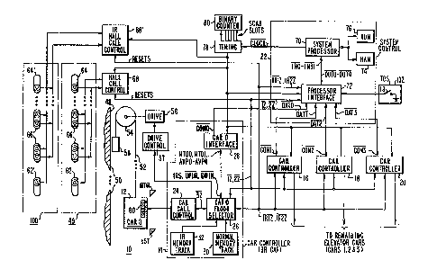
Figure 1 is a partially schematic and partially
block diagram of an elevator system which may be con-
structed according to the teachings of the invention;
Figure 2 illustrates diaqrammatically how activa-
tion of the IR feature according to the teachings of the
invention has the effect of doubling the number of floors
in the building, from the viewpoint of the dispatching
function;
Figure 3 is a RAM map of a memory maintained by
the dispatching function, wherein the dispatching function
l~fi377~ .
4 50,731
configures the building according to floor enables received
from all in-service elevator cars;
Figure 4 is a map of a memory location associated
with each elevator car o the elevator system, illustrating
an example of the floor enables sent to the dispatching
function when the IR feature is not active;
Figure 5 is a map of an additional memory loca-
tion associated with each elevator car which can be
switched to IR duty, with the floor enables illustrated in
Figure 5 being an example of the floor enables which are
sent to the dispatching function, instead of those shown in
Figure 4, while the IR feature is active; and
Figure 6 is a flow ch~rt illustrating how the
floor selector of an elevator car which may be assigned to
IR duty may be modified.
DESCRIPTION OF THE PREFE~RED EMBODIMENTS
The present invention relates to an elevator
system having a bank of elevator cars under group supervi-
sory control by a system processor or dispatching function.
The elevator system is of the type disclosed in U.S. Patent
4,037,688, wherein the dispatching function is universal,
i.e., the car controllers of the elevator cars have memory
tracks set to indicate which floors of the building they
are enabled to serve and the system processor or dispatch-
ing function "builds" the building configuration existingat any instant, by storing these floor enables from all
in-service elevator cars in a random access memory (RAM).
Thus, the dispatching function is not designed for a
specific buildin~, but can be used with any building
configuration without modification.
Figure 1 is similar to Figure 1 of the incorpo-
rated U.S. Patent, except modified to include a second or
inconspicuous riser (IR) 100 of hall call pushbuttons, in
addition to the normal riser 49 of hall call pushbuttons,
and also by adding a traffic director station (TDS) 102
126377.3
5 50,731
having a switch IR. Switch IR, when closed, enables calls
registered on the IR riser 100 to be served by a prese-
lected car, or cars. When switch IR is open, hall calls
registered on the second riser 100 are ignored.
More specifically, Figure 1 illustrates an
elevator system 10 having a single bank of elevator cars,
with the car controllers 14, 16, 18 and 20 for four cars
being illustrated for purposes of example. Only a single
car 12 is illustrated, associated with car controller 14,
in order to simplify the drawing, since the remaining cars
would be similar. Each car controller includes a car call
control function, a floor selector function, a memory
function which provides floor enable signals,. and an
interface function for interfacing with supervisory system
control 22, also called a dispatching function. For
example, car controller 14 includes car call control 24, a
floor selector 26, an interface circuit 28 and memory
tracks 30 and 32. The supervisory system control 22
provides the operating strategy of the elevator system
which directs the elevator cars to efficiently serve calls
for elevator service.
Car 12 is mounted in a hatchway 48 for movement
relative to a building 50 having a plurality of floors or
landings N. Car 12 is supported by a plurality of wire
ropes 52 which are reeved about a traction sheave 54
mounted on the shaft of a suitable traction drive motor 56.
Drive motor 56 is controlled by drive control 57. A
counterweight 58 is connected to the other ends of the
ropes 52.
Car calls, as registered by pushbutton array 60
mounted in the car 12, are recorded and serialized in the
car control 24, and the resulting serialized car call
information 3Z is directed to the floor selector 26.
Up and down hall calls are registered in a first
or normal rîser 49 of pushbuttons mounted on the hallways,
such as the up pushbutton 62 located at the bottom floor,
the down pushbutton 64 located at the top floor, and the up
~ 2fi3773
6 50,731
and down pushbuttons 66 located at the intermediate floors.
The hall calls may be read in parallel from a call regis-
tration module, or they may be recorded and serialized in
hall call control 68. The up and down hall calls lZ and
2Z, respectively, are directed to the floor selectors of
all of the elevator cars, as well as to the supervisory
system control 22.
Up and down IR hall calls are registered by a
second or inconspicuous priority riser 100 of pushbuttons
mounted in the hallways. The IR hall calls may be read in
parallel from a call registration module, or they may be
recorded and serialized in IR hall call control 68'. The
up and down hall calls lRlZ and IR2Z, respectively, are
directed to the floor selectors of the elevator cars, such
as floor selector 26 of car 12, as well as to supervisory
control 22. The IR hall calls are only served when switch
IR in the traffic director's station 102 is closed. The
position of switch IR, for example, may be detected by
system control 22 an~ an appropriate signal sent to the car
20 controllers 14, 16, 18 and 20 as part of command signals
COMO, COMl, COM2 and COM3, respectively.
Floor selector 26 keeps track of the position of
elevator car 12, and it prepares a binary advanced car
position signal AVPO-AVP4 for use by the system control 22.
Floor selector 26 also keeps track of calls for service for
its associated car, and it provides signals for controlling
the drive control 57. Floor selector 26 also provides
signals for controlling such auxiliary devices as the door
- operator and hall lanterns, and it provides resets for
resetting the car call control 24 and the hall call con-
trols 68 and 68' when a car call or hall call has been
serviced. Any suitable floor selector may be used. For
example, the floor selector disclosed in U.S. Patent
3,750,850 may be used, which patent is assigned to the same
35 assignee as the present application. U.S. Patent 3,750,850
describes a floor selector for operating a single car,
lZfi.377'3:
7 50,731
without regard to group operation. U.S. Patent 3,804,209
discloses modifications to the floor selector of U.S.
Patent 3,750,850, in order to adapt it for group control by
a programmable system processor.
S The supervisory system control 22 includes a
processing function 70, and an interface function 72. The
processing function 70 is a programmable system processor,
as indicated in Figure 1, which operates in conjunction
with a random-access memory (RAM) 74 and a read-only memory
(ROM) 76. The processing function 70 receives car status
signals from each of the car controllers, via the interface
function 72, as well as the up and down hall calls from
both risers 49 and 100, all as part of signals INO-IN31,
and the processing function 70 provides assignments for the
various elevator cars by way of inhibit signals UPIN and
DNIN. The assignments cause the elevator cars to serve
hall calls according to a predetermined strategy. The car
status signals provide information for the processing and
dispatching function 70 relative to which floors each car
is enabled to serve, and the processing function 70 then
makes assignments to the cars based upon this car supplied
information.
Supervisory system control 22 provides a timing
signal CLOCK for synchronizing a system timing function 78.
The system timing function 78 provides timing signals for
controlling the flow of data between the various functions
of the elevator system 10. Elevator system 10 is a serial,
time multiplexed system, and precise timing is generated in
order to present data in the proper timed relationship. A
binary counter 80 repetitively divides successive-like
periods of time into a predetermined plurality of scan
slots. Each floor of the building is assigned its own time
or scan slot in each repetitive time cycle. Scan slots are
generated in cycles of 16, 32, 64, 128, etc. According to
the teachings of the invention, a scan slot cycle having at
i;2~377^3
8 50,731
least twice the number N of floors in the building 50 is
selected. For purposes of example, it will be assumed that
there are 16 floors in the building 50, so a cycle with 32
scan slots (0-31) would be selected. The 32 scan slot
cycle is generated by a binary counter 80 having five
outputs. Thus, the binary address of scan slot 00 is
00000, the binary address of scan slot 01 is 00001, etc.
According to the teachings of the invention,
normal front (and rear) door hall calls registered on riser
lO 49 from floors 1-16 appear in scan slots 00 through 15,
respectively. Hall calls registered from floors 1-16 via
the second or inconspicuous riser 100 appear in scan slots
16-31, respectively. This arrangement is set forth dia-
grammatically in Figure 2, with the building appearing to
the system control 22 as though it had 16 floors when the
IR feature is inactive, and 32 floors when the IR feature
is active. When the IR feature is active, the fictitious
floors added to the building create a phantom extension
having the same number of floors as the number of floors in
the actual building.
System control 22 maintains a random access
memory (RAM) 74, a portion of which is shown in Figure 3.
Figure 3 is similar to Figure 5 of the incorporated U.S.
Patent 4,037,68~. Each elevator car has a normal memory
track 30 shown in Figures 1 and 4. A car (or cars) which
is pre-selected for exclusive service to calls registered
from the second riser 100, when IR switch is closed, also
includes the IR memory track 32 shown in Figures 1 and 5.
When switch IR is open, all elevator cars send the memory
30 track 30 of Figure 4 to the system control 22, and when
switch IR is closed, an IR car sends the memory track 32 of
Figure 5. The memory track 30 of Figure 4 contains the
normal floor enables for the first riser 49. These floor
enables appear in scan slots 0-15, and none of the scan
35 slots 16-31 are enabled. The memory track 32 of Figure 5
contains the floor enables for the second riser 100. These
floor enables appear in scan slots 16-31, and none of the
l;~fi377^3
9 50,731
scan slots 0-15 are enabled in the memory track of Figure
5.
Memory track signals MTOO and MTO1 for the up and
down service directions, respectively, are sent to car
interface 28 from floor selector 26, interface 28 sends the
floor enables to processor interface 72 as part of signal
DATO, and processor interface 72 sends the floor enables to
system processor 70 as part of signals INO-IN31. As shown
in the RAM map of Figure 3, system processor 70 stores the
floor enables, and from the floor enables up call masks and
down call masks are prepared and stored. Processor 70 uses
these masks, the car position signals, and the active hall
calls, lZ, 2Z, IRlZ and IR2Z stored in RAM to prepare up
and down assignments for each of the elevator cars. These
assignments are made by preparing inhibit signals for the
various elevator cars. If a car is assigned to handle an
up hall call which may be registered from the third floor,
for example, this assignment is made by inhibiting the
non-assi~gned cars from "seeing"an up call from the third
floor. These inhibits are sent from the system processor
70 to the processor interface 72 as part of command words
OUTO-OUT4. The processor interface 72 sends the inhibit
signals to each car controller interface as part of signals
COMO-COM3, and the car interface 28 sends up and down in-
hibit signals UPIN and DNIN for the proper floors to the
floor selector 26.
Figure 6 sets forth a program 108 which illus-
trates how the floor selector function 26 of each IR car
- may be modified according to the teachings of the inven-
tion. No modification of the system control 22 is re-
guired, as the system control 22 is universal in nature,
i.e., it does not require tailoring to any specific build-
ing configuration. No modification is required to the
floor selectors, of non-IR cars other than making the normal
memory track 30 twice as long as would ordinarily be
lZ6377.~
50,731
required, and loading the excess scan slots with zeroes to
indicate non-enablement.
More specifically, the program of Figure 6 is
entered at 110 and step 112 checks to see if switch IR in
TDS 102 is closed. Switch IR is closed when the IR feature
is activated. For example, the switch indication may be
made by a signal IRS which is a logic 1 when switch IR is
closed and a logic O when switch IR is open. Signal IRS
may be incorporated with signal COMO-COM3 sent by the
processor interface 72 to the car interface 28, and the car
interface 28 may separate signal IRS from the serial stream
of signals and communicate it to the associated floor
selector 26. It will first be assumed that switch IR is
open. In order to determine if switch IR was just opened,
i.e., if it was closed the last time program 108 was run,
step 114 checks to see if a flag IR is set. Flag IR is
stored in RAM associated with the floor selector function.
If flag IR is set, it indicates that the IR feature was
active during the last running of program 108, and has just
been deactivated. In this situation, step 116 resets flag
IR. Step 116 also sets the call inhibit tables to momen-
tarily inhibit the elevator cars from seeing any hall
calls, in order to provide time for the system processor 70
to build a new building configuration, i.e., the up and
down call assignment tables shown in Figure 3 are set to
inhibit the cars from seeing hall calls from any riser.
Also, a hall lantern inhibit bit for IR calls, which is
stored in RAM, is reset. Step 118 fetches the normal floor
enables MTOO, MTOl, i.e., the floor enable memory track 30
shown in Figure 4. If flag IR is not set, step 114 bypass-
es step 116, proceeding directly to step 118.
Step 120 packs the floor enables MTOO-MTOl in the
proper location in a binary word destined for the car
interface 28, and step 122 fetches the binary advanced car
position signal AVPO-AVP4. Step 124 checks flag IR. Flag
IR will now be found to be reset, and step 126 packs
AVPO-AVP4 in the interface word. Step 128 completes and
37~3
11 50,731
sends the interface word to the car interface 28. The
floor selector 26 may then go on to other tasks, indicated
generally at step 130, or into a time delay loop, in order
to enable the system control 22 to build the new building
configuration, and to prepare and send inhibit assignments
to the various elevator cars.
Step 132 then reads the up and down inhibits UPIN
and DNIN, respectively, i.e., the inhibit assignments from
system control 22, and the inhibit assignments are stored
in a temporary location in RAM. Step 134 checks flag IR.
Flag IR will be found to be reset at this point, and step
134 proceeds to step 136 which stores the floor inhibit
signals in appropriate hall call inhibit tables in RAM.
Step 138 proceeds with the normal call answering functions
of a floor selector, and the program returns to the start
110 from exit 140, or to a priority executive if the
processor which runs program 108 is also assigned to tasks
other than the floor selector function.
When switch IR is closed by an attendant at the
traffic director's station 102, to activate the IR feature,
step 112 will now branch to step 142 which checks flag IR.
If flag IR is not set, it indicates switch IR was open the
last time it was checked. Step 142 proceeds to step 144
when flag IR is not set. Step 144 sets flag IR, it sets
the inhibit tables for the purpose explained relative to
step 116, to enable the building to be reconfigured, and it
sets the hall lantern inhibit bit for IR calls so the hall
lanterns are not illuminated when IR calls are being
served. Step 144 then proceeds to step 146 which fetches
the IR floor enable memory track 32 shown in Figure 5.
Step 120 packs the IR floor enable signals MT00
and MT01 in the interface word, and step 122 fetches the
advanced car position ~ignal AVP0-AVP4. Step 124 will now
find flag IR set, and step 148 increments the advanced car
position signal AVP0-AVP4 by N, the number of floors in the
building, which in the present example is 16. Step 126
packs the modified advanced car position signal AVP0-AVP4
~.263773
12 50,731
into the interface word, and the program continues as
hereinbefore described through steps 128, 130 and 132.
Step 134 will now find flag IR set, and step 150 subtracts
N, i.e., 16 in the present example, from the up and down
floor inhibit assignment signals UPIN and DNIN,
respectively. Step 136 stores the modified assignments,
and then proceeds to step 138. Step 138 performs the
normal call answering functions of the floor selector.
In summary, the elevator system of the present
invention handles the normal riser of front and rear door
hall call pushbuttons, and also a separate inconspicuous
priority riser ~IR) of hall call pushbuttons, all with a
single dispatching function. Further, no modification is
required to the dispatching function. The car controllers
of the controlled bank of elevator cars notify the dis-
patching function which floors they are enabled to serve,
and the dispatching function configures the building
accordingly. When the additional riser is activated, such
as by a switch, each car pre-selected to serve IR calls
notifies the dispatching function that it is enabled to
serve floors which are not actually in the building. For
example, if there are N actual floors in the building, an
IR car notifies the dispatching function that it is enabled
to serve floors N+l to 2N. Also, each IR car, before
sending its building position to the dispatching function,
adds N to its advanced car position signal. The dispatch-
ing function reconfigures the building in its RAM and makes
assignments to the IR car or cars for floors N+l to 2N.
Upon receiving such assignments, each IR car subtracts N
from the assignment. Thus, the full power o the dispatch-
ing strategy of a single dispatching function is simulta-
neously applied to two independent risers of hall call
pushbuttons. Even though the dispatcher function will not
normally assign the same scan slot to two cars, this effect
i5 achieved without modification of the dispatcher, because
the dispatcher is "tricked" into assigning two different
scan slots associated with the same floor.