Note: Descriptions are shown in the official language in which they were submitted.
T~IU 2-001
DUAL VOLUTE MOLTE~l METAL PUMP AND SELECTIVE
OUTLET DISCP~rMI~TION ME~NS .
BACKGROUND O~ THE INVENTION
This invention provides over-all means for circulation of
mol~en metals under a substantially constant head of pressure
and flow rate in a substantially laminar flow downstream of
the egress of the pump whlch 1~ adapted for use submerged in
a meleing/holdin~ furnace.
I~ further provides a control ~eans fsr direction of a
selected one of two downstream egress chann~ls wi~h molten
metal by ~eans o combination of the molten metal pump in
downstream co-operatlon with a downstream flow selector means
for said ~election of any one of the said two channel means,
said flow selector means preferably integral with the single
output orif$ce of the molten metal pump.
The selector means may also be operated independently
physically as a separated unlt down~tream of a prlor art pump
or a gravity fed source of molten metal ch~racterized by
havin~ a cons~ant pressure head and flow rate as might originate
from molten flow into a tundish placed in a holding furnace on
an upper foundry floor, without integral connection with a
pump, the latter operations are no~ often feasible and limit
foundry flexibility in moving molten metal from one furnace to
another, or from one urnace ~o two or more ~eparated down-
stream operations.
By mean~ of the preferred combin~tion, one may feed a
single metal flow se~uentially to one of ~wo or more operatlon~.
~etal may be sequentially cast, for example, rom a molten
Rupply into various downstream operations producing ~o.lid ~et~l,
TH~ 2-001
~L2 ~
forms such as lngots, sheets, foils, tubes or rods, etc,.
by use of one unit fluidic control or a ~lurality of said
wnit controls in serie~, if desired.
Both soluble and insoluble zross solids includin~ fluxes,
sla~, unmelted metals includinz iron, silicon, etcO, fire-
brick refractory fra~ments, aluminum oxide occlu~ions, etc.,
which can damage the downstream volute pumps accumulate upon
normal handling of molten metal in refractory urnaces and
tend to collect upon and af~er formation in meltin~ and hold-
in~ furnace~. As the foregoing partlculate lmpuritic~ native
to handling molten zinc are inherently lighter and ~end to
10at, they tend to be drawn into top fed impeller pumps,
Hence, for handlin~ molten zinc bottom fed pumps are normally
selectedO On the other hand, with molten aluminum and its
alloys, occluded impurities are most often heavier than the
melt and tend to agglomerate and settle. Liquid aluminum metal
fed into bottom-fed volute-impeller pump~ have been generally
avoidedO
The prior art has su~gested multiple specialized molten
metal pump a~semblies by use of alternative pump elements,
including drive shats, pump impellerg as illustrative. Shorter
drive shaftq have been used where top eed of molten aluminum
metal to a top fed impaller pump i~ desired. If metallic
zinc was to be handled, a longer drive pump shaf~ and co-relatsd
inverted cup impeller fed from a bottom in~ress pump was
assembled. Pump as~emblies ha~e been 80 designed as to provide
bottom fed molten metal pUmp8. See Swaeney et al., U.S~ Patent
3~048/384~
One prior ar~ solution has proposed a system of rota~y
baffles, referred to ag "deflector disks", driven on the same
~ THU 2-001
~æ~L~z~
vertical drive main pump shaf~ provided controlled circum~er-
ential clearance of molten metal from the meltin~ furnace by
~djustment of the dl~k clearance on the common drive shaft
both above and below annulAr top and bot~om fed sinzle pump
ingress means. See Sweeney et al., U.S. Patent 3,291,473.
llere, a volute pump has been described to be useful to
pump molten metal inwardly through a single pump ingre~s mean~
ed from the top. However, a slngle pump impeller devoid of
volute m~an~ is employed.
I~ should al80 be noted that in the top and bottom entry
modifications, patentee does no~ u~e a volu~e pump and the
utility does not permit ~he higher temperature~ e~sential in
handlin~ mol~en me~als and i~ intended for generally lower
t~mperature melting point chemicala. In either case, entry
is through and pa~t rotary, driven, de1ector disks slightly
upstream of ~he m~tal flow entry lnto the pump.
It is well known, however, that similar rotary power drlven
disks spinning within an encloged cle~rance provlde hi~h shear
dispersive forces. The high ~hear rate produced effects
unwanted dispersion of forei~n matter as referred to above
which contaminates the melt stream. Rotary di~per~ion action
of the described classifiers tends to defea~ the filtra~ion
intended and to break up and disperse in~oluble solid matter.
Here, dual volute pump~ opera~ing from a single shaft
separately xeceive influx o molten metal whlch flrst is
fil~ered of all su~pended ~olid~ ln the mel~ by ~n upper and
lower restricted ingress zone co~pletely about the perlphery of
the submers~ble pump which lnsures that the pump clearances
are not unduly worn or damaged by entry of any one of the
foregoing ~nmelted accumulated particul~t~s.
-3-
THU 2-001
One prlncipal advance over the prior art herein dlsclo~ed
i~ embodied in th~ moving part~ free, selective fluidics
flow control means, particularly when operated in conjunct~on
with the dual ingre~s dual volute pump, both of which are more
fully described herein~
The liquid metal flow upon egres~ from the pump and
enterin~ the downstream transition control mean~ i8 control-
lably dlverted into a selected one of two diver~ent controlled
downstrea~ condults or channel~ without interference wlth
over-all through~put flow rate.
Commonly the principal control of molten metal flow
egressing the pump has been solely through control of the pump
operation. The limitation has been ~rimarily an on-off; flow
or no-flow; operatlon where the driving motor means control of
resultant metal flow through the pump i8 not in~tantly re~ponsiv
to the "on-of" si~nals.
~ en ~n "on-off" flow con~rol 18 employed in a moving
s~ream of metal, particularly, a "water hammer" develops which
is detrimental to the pump function and may cause breakage of
the graphite part~ required in the pump manuf~cture,
This invention makes possible downstream selection of
alterna~ive meltln~ and holding fu~laces and re~circula~ion
within and between such furnaces and alternative delivery of
a single 3tream of molten metal ~9 one of ~wo pre-selected
downstream operations.
The fluidic~ devices of this lnvent~on oan be used in
tandem in plural number, if deslred~ makin~ continuou~ oper2-
tion from a single melting furnace, or a plurality of mel~ing
or holding furnaces feeding a ~eries of varying downstream
operations el~ctively and sequen~ially.
T~U 2-001
~2~ %~ 1
S~ ~ RY OF THE INVENTION
The invention as herein di~clo~ed provides a fluidics
operated molten metal flow control device operable downstream
of a melting and/or holding furnaee under a relatiYely constant
ingress head and laminar ~low rate. Under the foregoing condl-
tion~, a fluidics controlled transition zone controls flow of
a single upstream enterlng vo'lume of liquid molten oetal into
one of two downs~ream alternative bifurcated egres~ channel~.
The dual channel~ outwardl.y diverge from one another at an
acute angle forming interiorly thereof the basic position of
solid conjoined trian~ular splitter element to be affixed
thereon.
The acute angle of the splitter elemen~ exte~ds up~tream
and ori~inates the demarcation point of internal stream flow
divlsion~ The division apex line defines the ori~in of the
outwardly diverglng channel~ downstream of ~he splitter and
physically extends operably u~stream into said transition
zone volume.
Upon pas~a~e of a single molten metal stream into the
upper in~ress or opening lnto sai~ transltion zone, the single
stream is diverged into a selected one of the ~wo divergent
downstream outlet channels bu~ directed in a single ~tream
through a common and expanded volume sometimes referred to
herein as the tranBition zone and one slde of the spl itter in
a pre-selected downstream channel,
The fluidics control zone tran~itiQn piec~ integrally
join~ the ~ingle up~tream en~ry channel through a transition
zone of expandin~ vol~me, split by the leading acute an~le
~d&e o ~ splitter elsm~n~ partially intruding up~tream lnto
_5_
, . . .
. .
~,,
THU 2-001
the aforesaid ~ransi~ion zone but downstream to e~tablish the
inner walls of the two divergin~ bifurcated channels. The
downstream outwardly bifurcatin~ ~in~le channels of the transi-
tion æone are herein referred to for convenience as conduits
or channel~ A and B. Corresponding stream~ flowing through
said channels are corre~pondin~ly referred tO a~ stream A
and s~ream B.
Only one selected stream (A or B) flow~ through a corre-
sponding downs~ream channel (A or B) und~r a Eiven flow
control at any one time.
The specifle design of the fluidic~ control transition
zone and its co-operative elem~nt~ can be specifically modifled
to meet required ends for specific operations and demand condi-
tlons.
One modification of the ~ransition control ~one permit~
a Eail #afe operation 80 that flow of stream B through conduit
or leg B, for example, establishes that stream B will dominate
(unle6s manually over-ridden).
To operate thereafter through conduit A, the remote
control device must be set or fixed in operatin~ position to
re establi~h and maintaln an elected flow pattern through
non dominant leg k. Stream opera~ion through condult B will
be resumed automatically upon relea~e of the control o~herwise
directing ~he mol~en stream ~hrough channel A~ ~See Figure 7.)
In another, pos~ibly preferred, metastable ~ode of opera-
tlon the ~ransi~lon zone i8 as 8hown in Figure 6. Here, both
eonduit A and ~ream A, or conduit B and stream B only require
appropriate in~ection of a puff of compressed g~8 from the
remote control ~o effect input of a controlled jet of eon~rol
-6-
..
THU 2-001
stream gas into the appropriate control orifice and into and
upstream of the transi~ion zone to imping2 upon the po"er
stream to convert the stream flow from channel A to channel ~,
or vice versa.
Initlal de~ign of the fluidic~ controlled transi~ion
zone may restrict the cro3s-sectional area of one selected
channel or le~ A or B.
l~ile it is possible to devise the cross-sectional
patterns of the channels immediately upstream of, wi~hin,
and downstream of the transition control including ~he single
immediate ingress as may be illustrated elsewhere, it is
preferred ~n the best mode of practice known, tha~ the
cross-section be of ~enerally slliptical form wherein the
major axis i8 vertical, as 19 illustrated in Fi~ure 8.
Such sectional control assists in maintaining laminar flow
and optimum practical use of the"Coanda" or "wall effect".
O~her modifications are within the knowledge o ~he fl~idics
art. Other po~sible control modification~ are not precluded,
however,
In the preferred form of the invention the molten me~al
pump is constructed upstream and integrally a part of the
downstream ingre~s control channel and metal stream into
~he single entry passageway of the downstream fluidics control
transit~on zone.
While the pressure head and flow control conditions
essential to functional operation~ of a fluidics control and
~ransition zone means may be established in theory and prin-
ciple by gravity flow from an elevated source of supply of
the required molten metal, su~h means are not amenable to
THU 2-001
~aried plant conditlon~ and opera~ions. Operations are
then limited to sin~ular and unlque posi~ions and location~
within specialized building structure~. Fur~her, in gravity
operation speclal efforts may be necessary to assure the
fluidic~ control unit be supplied with auxiliary heat to
prevent (or to re-mel~) metal freeze-ups when the ~r~vity
uni~ i8 forced to be shut down unexpectedly.
While a compre~sed ~as useful in operating the transition
control zone i~ usu~lly ~n inert ~as, lllus~ratively nitrogen,
in somR ln~tances minor percenta~es of usefully reactive ga~es,
i11ustratively chlorine and/or arg~n, etc.~ may be blended
into the control gas stream as an aid ln maintaining pur~y
of the molten metal.
Impact of the pressurized control ga~ stream interiorly
of the transition zone below the initial ingress point and
upstr2am of the splitter initiates turbulence and development
of a gas bubble. The development of a "separation bubble"
initiates the e6sential destruction of the existing "Coanda"
or "wall effect" and momentary ~tream flow ins~æbility within
the transition zane a However, as the de~tabiliz~d ~tream
flows close to the alternate and dlver~ing wall the "wall
effect" brings the molten metal ~re~m lnto the alterna~ive
and diverg~ng bifurca~ed downstrgam leg. This completes a
directional flow change over and into the selected, alternate,
downstream ehannel or le~ as defined by the splitter apex
permanently locat~d in the enlarged volumc fur~her downstream
and interior of ~he expand~ng transition plece volume.
The dynamic energy content inherent in the molten metal
power s~ream cour~ing downstream from the pump (or head) i~
-8-
-
THU 2-001
~L~,~..~
~he principal source of energy in the fluidic dynamics of
the fluidica flow directional control unit d~scrlbed herein,
A ~econdary compres~ed gas control stream originating
at the remote control point provides the ancillary ener~y
source essential ~o efect growth of the separation bubble
and destroy the pre-e~tabli3hed w~ll effect~ The compre~3ed
~as power ~tream i8 30metime~ referred to a~ the ~econdary
control gas ~tream.
So far as i8 presently know~, movemen~ ~nd transfer of
mol~en me~als and control o flow ha~ been principally u~eful
in lncreasing and su~taining produetion of castings~ sheet,
foil, etc~, by ~speclally de~igned m~lten metal pumps prin-
cipally con~tructed of ~ refractory non-metal, most often
~raphite, to withstand the elevated temperatures, erosion
and ~orrosion due to movin~ contact with molten metal at
temperature~ illustratively from about 1200 to 1600F at
a choice of several downstre~m plant operations. . .
Only two pumping conditions were previously controlled.
The power source, compressed air or a long shaft directly
driven electrlcal motor~ could be "off" or "on". Molten
metal flow either "stopp~d" or being actively pumped from
with~n the melting furnace down~tream thereof~
Molten pump ~ailures prgsently most oten occur during
sear~ up or ~hut-down due to sudden flow rate chan~e~.
Hammer effects when a pump i8 ~urned "off" develop severe
~trains in the pump and wear through reduced clear~ce~ within
the pump i8 a~celerated. Wi~h the pre~ene combination of
pump and re te control means as~ociated, and preferably
integral therewith, pump ~hut-off to con~rol flow i~ no long2r
mandatory,
¦ THU 2-001
'~
Use of optional forced melt circulation within the
mek in~/holding furnace, now made ~ractica~le~ has se~eral
advan~a~es, The time nQcessary to prepare a melt may be
~hortensd. Development of metal oxide~ and other impurities
wlthln the melt h~ le6~ time to be produced due to increa~ed
meltin~ rate wi~h forced circulatlon of the melt over the
~olid 3urfaces. Meltin~ o~ ~olld metal scr~p i~ poasible at
hi~her furnace turnover ra~e if the ~hear rate of movement
of the liquid pha~ over the solid scrap ~urface~ during
melting periods i8 enh~nced.
However, known material~ and means useul to ~hange
direction of flow which ch~nge~ shear rate~ B~ the molten
metal powers~ream i8 either throttled down~ as in stopping,
or increa~e~ in ~hear, if starting up. This action occurs in
prior art valves depending upon moving parts to throttle
moving stream, a~ illus~rative.
Known valve~ are not adaptable to the control of high
temperature lten metal stream~, permitting as illustrativ~,
an alternative pumping circulation pha~e within the melt~ng
furnace and a second egre~s phase where the prepared molten
metal is delivered to a point of u~e apart from the melting
furnace.
A~ indicated above, molten metal - air (oxygen~ contact
mu~t be avoided wherever po~ible becau~e of the high oxida-
~ion reaction rate (of aluminum and oxygen~ and con~equent
loss of useful m~al due to the r~pid ~ormation of in~oluble
contaminating heavy aluminum oxide par~icle~, aB i8 well
under~tood,
Thie invention prov~de~ a ~ovel mean~ of co~trol o~
the fl4w of molten metal ~hrough ~elected and alt~rnatlve
THU 2-001
channels or conduit mean8 without corrosion or wear upon the
surace of moving control valve6 designed to chan~e rates of
flow and thereby undergo wear. Change in flow directions
into one of ~wo el~c~ed flow path~ as i~ accomplished herein
without materially interruptin~ the normal flow ra~e of th~
princlpal or "power" molten metal ~tream h~s not been hereto-
fore known.
In the utilization of the fluidic~ controlled transltion
; control mean~ of this invention the requiremen~s of standard-
lzed pres~ure, flow ra~e and ~he laminar flow character of
the stream are ~mportant to the dependable operation of the
device.
In use, the pump ~ssembly a~ herein described is sub-
merged in molten metal. Molten ~etal enters ~he upwardly
extending central cup of the top volute pump by pa~sage through
~, an extended controlled molten metal clearafice zone or volume
which provide~ effective filter m~ans. The extended filter
zone is created by means of an extended ~pecial ingress volume
defined by the dual top horlzontal spàced apart plates of the
I pump assembly ~hrough which top llquid entry occur~ and a
i like bo~tom ingres~ zone created by spacer feet between the
interior flat bottom of the furnace and the bottom horizontal
plate o the submerged p~mp baseO Note th~t bo~ the en~ire
periphery o ~he pumpj bo~h bop and bo~om, d~fine ~ filtra-
tion zone ingress means lnherent whe~ the pump i~ in uAe
These clearanee entry 810~8 or filtxa~ion ~lements a~sure
absence of in801ublc accretions in ~he incom~ng mel~.
Fu~ther, a~ the vol~e of ingres~ liquid entering the
pump ori~inate~ over bo~h top and bottom of the pump per~phery,
11
THU 2-001
dL~DYtd2~;
thu~ the developed ~hearing 8tre89 i~ insufficient to disinte-
grate occluded insoluble "tramp" material~ commonly contamina-
ting a molten metal durlng ~elting, holdlng and transfer.
~hunk~ of refractory brlck, undi~solved 8illcon meta~,,oacluded
insoluble metal oxides, e~c., cause at best e~ce~sive wear,
and more often abrupt breaka~e of pump part~ which are at
close tolerance~,
Carry ~hrou~h of in~oluble metal oxlde aCcretionR i8 not
only ob~ectionable in proce~sing m~lten m~tal~ but insoluble
metallic impuritle~ in the mel~ if not removed downs~ream,
are a cause or reie~tio~ of co~pletely formed metal part~ and
useful product~ derived therefrom.
The. disclo~ure herein com~rises two clo~ely related
inventive entities most often in advantageous functional
combination, but e~ch of which can be operated separately,
but always ~dvflntageously arranged in series compri~ing the
improved molten metal pump and the correl~tive downstream
control mean~.
The principal novel entity in the combination comprises
a molten met~l fluid flow ~irective control device dependent
for itB operation upon a reliable ~ource of molten metal flow.
~elatively con~ant flow rate, constant pre~sure head and
freedom from occluded insoluble particulate~ And es~entially
laminar flow are derivat~ves essential and dependent upon a
qu~lity molten metal p~mp upstream of the said control.
The flow control device of this inventive combination is
charac~erlzed by a ~in~le fluid ingress channel, dually diver-
gent blfurcated egres~ channela down3tream and intermedlately
of ~aid single ingress andl the b~ furcated egras~ ch~nnels a
- 1 2 -
~¦ THU 2-001
~L2~i~%~
fluldlcs ~ontrolled transition zone, 3 stream directing exit
orifice t~rminating said sln~le ingreas mean~ down~tream of
: sa~d e~r~s and entering said transition zone, oppositely
dispoaed inwardly directed pressurized ~as control ports
adap~ed to control dlfferential ~as pres~ure3 interiorly of
said egress zone At said exit oriice, said transltion zone
expandin~ ln volume downstream to ~ccommodate ~ sln~le enlarged
entry zone in~o ~aid dual bifurc~ted downstream egress channels
which channels separate and diverge at an acute angle 7 interl-
orly thereof iB et a conjoi~ed ~olld triangular splitter
element the apex of which ex~end~ upstream i~to the downstream
terminus of ~aid expanded transitlon zone volume; said
diagonally opposed ~as pressure control ports upstream in the
transition provide control from a remote poin~ of origin of
said essential pressure controlling gas ports~
The pump so~rce specifically referred to above of a m~lten
metal flow having relatively co~stant lamin~r flow rate,
pressure head and freedom from "tramp" particulate solids is
preferably operated in inte~ral combination wi~h the fore-
goin~ fluidlcs molten metal flow control device. The~e
separately and dual function~, but preferably physically
unitary elem~nts, comprise in combin~tion a uni~axy molten
metal pump with selective directional output control means
downstream thereo~, The comb~nation assembly provides inter-
relating and inter-related lmprovement in the handling of
refractory molten m~tal by f~nctional immers~on in mel~ng/
holding furnaces.
,,
/
I ~
BRIE~ DESCRIPTION O~ THE DRAWINGS
Fi~ure 1 is an elevatisn partially in sectlon not2d
with parts broken away of a molt~n metal pump in operative
~ association with a ~olten metal bath or mel~ing furnace~
: Figure 2 is a psrtial se~tional view along the line
2 2 of figure 1.
Figure 3 ia ~ top v~ew of th~ unit pu~p assembly
indicatin~ co-relation of the pump ass~bly with a preferred
form of a s01ective fluidics control zon~.
Figure 4 is an enlarged partial elevation in section
detailing essentials of the molten ~etal pump and a fluidics
. control zone.
;~ Figure 5 is a top ~ectional view fllong the line 5-5 of
Figure 1.
Figure 6 is a sectional view along the line 6-6 of
Figure 1 de~ailing operational elements of the fluidics control
device and volute pump.
Figure 7 is detailed develop~ent o~ an al~ernatiYe
arrange~ent of another specific modification of the fluidics
control zone.
,~
Figure 8 is a sec~ional view as seen upstrea~ of the
broken line 89 of figure 6 and 7.
THU 2-001
DETAIL~D D~SCRIPTION OF THE PREFERRED E~BODIMENT
This invention i8 dlrec~ed to a fluidics flow control
device ~o make posf,ible dlvisi~n of a sin~le ~lten metal
egre~s ~tream into a pre-selected one of two pofg~lble e~re~s
condults. In the broadest aspect, the flow control device
can be detachably affixed downstream of a relatlvely constant
source of mol~en metal flow h~vin~ the required pre~sure head
and flow rate ~o provide reliable operation throu~h a down
stream flu~dics operated dlrectional control meanFg providing
for selectioslal direction of the metal ~ream through one of
two avallable channels.
A plurality of the fluldlcs control devices may also be
set up in series or in a eontinuous downstream sequence to
provide a plurality of controllably directed me~al streams
from but one original single m~lten met~l stream.
A controlled source o molten metal havin~ requisite
pre~sure he~d and controlled flow ra~e i~ pre~er~bly obtalnad
from use of a molten metal pump ~ubmersed in a molten metal
meltin~ and/or holdin~ furnQce, It i8 al80 conceived of
originating in select foundries where the meltin~/holding
furnace~ are a floor or more above ~he casting or metal
forming operations~ Thi~ mean~g depend~ng upon gravity flow,
may ~upplan~ the otherwise essential liquid metal pump.
A ~r~vity 8y~tel3 will perm:it operation of the fluidics control
device of this invention when the output rate i8 held relatively
con~tant. Gravity a~tachm~nt i~ no~ oten adaptable to general
plant operation a~ a separate flow control ~ t. 'The use
of a ~ood quali~y prior art ~olten metal pl~mp i~ also potentiall r
-15-
:.
I
THU 2-001
useful in ~equential combination of one, or a plurality of
more than one fluidic~ flow control devices ~8 herein disclo~Pd.
The preferred embodiment of the fluidi 8 con~rol æone
of thl~ invention 1B lntegrally ~ part of and supported
within a molten metal pump assambly. The combination bccomes
a ~nitary piece of processing e~ulpment. In use; it 1~
functio~lly ~ubmerged in a molten meltin~/holding furnace.
The unitary assemblies h reln are portably movable upon
demand from one metal/holding furnace by mean~ of power lift-
in~ unl~. Advantageous plant operation fl~xiblllty i8
thereby ~llowed.
The preferred embodiment of ~he fluidics control unit
of this invention i~ shown and d~cribed as a u~ieary par^c
of an inventive metal pump, al80 described here, particularly
accommodated to the tran~fer of both molten aluminum and
~olten zlnc.
Heretofore, beeause of the es~enti~l lnherent differences
in phy~ical and chemical behavior of ~hese m~tals in molten
state, either two separately desi~ned pumps, or one pump having
electlve parts, assembled for ~he ~pecific elected metal ha~
been dlsclo~ed in ~he prior ar~.
This wri~ing disclo~es a pump integrally as~embled ~o
opera~e in con~unction with a fluidics control device. The
herein disclosed improved me~al pump ean be used without
modification and provides molten metal ~low characterl~tics
particularly deAirRble in direct down~tream operatlon of the
~aid fluidios control unlt fir~t above lntroduced.
Referring more particularly to the drawlngs:
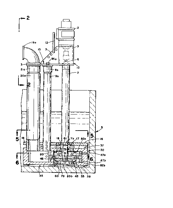
A metal meltingtholding furnace 5 in Figure 1 holds
portable molten metal pu~p as~embly 10 partlally i~mer~ed
l THU 2-001
i ,~
ln~o ~nd elevated into positlon by power llft means ~hrou~h
hanger 1~ of mounting ~s~embly plat~ 3 of top ~tor mounting
a~sembly 15. Air dr~ven motor 2 ~uppor~ed by a ~op motor
untin~ as~embly pl~te lS drive~ pump 30 throu~h power sha~t
7 and through univer~al join~ 6 and b~yonet coupling 4. A
p~ir of c~ntrally drilled vertic~l po~t~ 9a and 9b, and a pair
of centrally drilled hollow riser~ 20a and 20b pa88 throu~h
horizontal ~uppor~ plate 3 ~erminatin~ ln elbows l9a and ~Oa
above the support and riser ~ockets 21a and 21b, ~upportably
connect below and adhefiively ~et within subm~r~ed rec~ilinear
pump base 30~ Posts 9a and 9b, centrally drilled rlsers 20a ~nd
20b and all other parts below the po~ ~nd riser ~ockets
6ub;ected to be ~ubmersed into molten metal furnace box 5 are
fabricated of refractory sub~tances, graphite being generally
u6ed. Silicon carbide i8 often used where wear 1B greate~t.
All pa~t~ are m~chined to clo~e tolerances; and a~embly,
where not otherwise ~hown, i8 obt~ined through u~e of high
temperature adhes~ves.
Driven shaft 7 is rotatably supportPd in top plate 16 of
box 30 and extend~ centrally downward through bore 60 to a
threaded shaft of bottom end 7c. Bearing moun~ 17 and mounting
ring 18 ar~ fitted i~ a top vertical bore throug~ ~late 16
and support ~haf~ 7b rotatably within said a~sembly~ Lower
shaft end 7c threadably engages bo~h upper ~olute impeller 46
and lower volute lmpeller 45 of dual volute pUmpS m~unted back
to back. Both 45 and 46 impeller~ are ~imNlt~neously driven
in a clockwl~e directlon (as i~di~a~ed in Figure 6~. Axlally
centered disk-llke impeller elem~s 83a of impeller 46 extends
upwardly and ~utwardly an~ 83b ex~ends outwardly and do~nwardly
.
THU 2-001
from i~pell~r 45 within bore 60. ~ach of the~e disk-like
lmpeller element~ 83 create an axial uppPr and lower ~ntry
volume 82a and 82b (Fi~ure 6 - Fi~ure 7).accommod~t~d to
receive molten metal f rom interior of furnace 5 throu~h ~ep~r-
ats entry m~an~ a~ fOllOWB:
Upon clockwi~ rotation of shaft 7 through actlvation of
motor 2 volute impellers 45 and 46 are rotated withln their
re~pective ~tationa~y volutes 47a and 47b. Molten me~al flows
from the submerged molten metal environment of furnace 5
through restricted top en~ry volume 37 created between top
plate 16 and top plate of box 3~ ex~endlng co~pletely about
the pum~ base periphery ~nd into the interlor of the axial
volume of elemen~ 83a of top volute impeller 46~ Separately,
molten m~tal flows downardly about the exterior perlphery of
box 30 ~hrou~h restrlcted pa~sageway 36 into bottom bore 60.
Spacer studs or le~s 35 m~unted on the planar bottom of
box 30 define a separAte and reetrict~d entry passageway
interiorly of dl3k-llke axlal volume 83b of lower volute 45.
Each of the above restric~ed ~nd separated entry pa~sageways
36 and 37 act to filter out su~pended sollds whlch m~y be
unmelted chunks of metal scrap, silieon metal incorporated a~
an alloying element in the mRl~ which w~ll ultim~tely dis~olve,
contamlnan~s which include lnsoluble foreign msterial includ-
ing refra tory brick spalled frum furnace wall~, chunks of
~ement, ln~olubl~ metal oxlde accr~tions, etc., mu~h of the
above, particularly insoluble ~Itramp~ occulslon~ when pr~sent
eontrlhute 'co exce~ive wear and tear and often breakage of
pump element~ lncluding volutes and lmpellers.
THU 2-OOl
'~
~ lth driven ~haft 7 acti~ely driven throu~h motor 2,
centrifugal force~ actin~ upon each of the molten me~al
~treams from ~he furnace interiors flowin~ lnteriorly into
the axial cavitie~ 83a and 83b force the molten metal therein
outwardly and rearwardly (to the dlrection of rota~ion) through
plural impeller passageway~ 79 under the ~o increa~ed centrl-
fugal pre~surea developed. Dual 1uid molten metal stream~
are expelled from their respective volute pump~ in the volumRs
be~ween the stationary volute piece~ 47a and 47b and volu~e
impeller~ 45 and 46 into a single ef~lux straam downstream of
the pump through lten metal pump exlt orifice 80.
In the preferr~d orm of the invention a~ here more
specifically of concern, the ~ingle exit strenm of molten
metal from the exit oriflce 80 is pumped through common exlt
channel 8S ~Figure~ fi and 7) which i8 ~180 the common ingress
point o~ ~he mol~en metal stream into the ups~ream end of
fluidics controlled transition zone 5~ at 87.
At this point the m~lten metal enters the transition zone
under sub~tantially a constant pres~ure and flow rate of the
li~uified metal.
If one eleot~, the fluidics operated transition control
meanR 50 can be totally replaced with an uninterrupted conduit
section (not ~hown3 from the upstre~m entry at 87 thereln
through ~ single down~ream channel ~functloning as a cho~en
one of two bifurcated downs~ream le~ or channels A or B).
The ~oregoing change ellmlnates ~he added u~ility and
adaptability o ~he fluidic~ control zone SQ and the choi~e
of di~tribution of any one of two downstream liquid molten
metal outputs at a ~iven time wi~houe fully utilizlng the
19-
T~U 2~001
inheren~ lmprovements prPviously di3closed in expo~ltion of
the :lmpro~ed molten metal pump a~sembly.
l~owever, the preferred form of the invention ~brace~
both the advances in versatility and capacitle~ of the metal
flow as are inherent in the above de~cribed molten ~etal pump
unit havin~ a~ integrally ~ part thereof the fluldic~ capacity
to effec~ a change in directlon of the pump outlet ~trea~
wi~hout movable m~chanlcal parts.
Returning to the dr~win~, Fi~ure 6 and Figure 7 pick
up the down~tream flow of lt~n m~tal as it egre~ses under
required flow conditlon~ from the upatream pu~p and e~resses
downstream therefrom into the fluidics control transition
zone 50 of the down~tream flow direction fluldic~ selector
device.
The fluidica control zone for referral $8 so~etimes
herein referred to and descriptively ident~f~ed as a control
zone transitlon piece 50 althou~h the entire control unit iB
preferably integral with the improved pump.
Satisfactory~opcration of the fluidics control zone as
a unit embrace~ not only the lmn~diate transition zone 50
bu~ also generally including the flow control æone se~ out
by dot~ed line~ 87 and 89; and further includes con~lderatlon
o the immediate ingres~ zone 85 ~nd the two le~ A and ~ of
the alternative flow streams A and B downstream~
In the pre~rred form o the inY~ntion, ~he cros~ sectlon
of the connectin~ condult betwe~n th~ liquid metal leavlng the
pump a~ 80, the crofls sectional pa~te~n ~hrough ~ny ~ec~ion
of the exp~nding volume transit~on zone 85 and the ~wo leg3
A and B are of importanee to obtain ~he op~imum influence of
-20-
TJU 2-001
2 ~
fluldics forces. The "Coanda" or "w811 ~ffect'l depends upon
relativ~ constancy of pres~ure he~, pressurc upon the moltPn
~tream flowln~ w~thin the enclosed wall~ and a ~ubstantlally
lamellar or axi~l flow of th~ m~tal through the control unit
except under activation of ~ flow ch~n~e direction by impin~e-
ment on and into the downstream power stream of molten metalby means of a controlled pressurized ga~ ~ream.
It ~8 preferable in the cons~ructlon o~ the 1uldics
control for the purpsse~ herein ~hat ~he imned~ate pump egress
8S, the control zone S0 and the two bifurcated downstream l~gs
be con~ru ~ed from ~raphite tubes h~vin~ an elliptical section
wherein the ma~or axl9 thereof i8 vertical. Rddy current~
withln this c~itical zone are not encouraged, m~ximNm side
"wall effect" i8 obtained over the lareest ma88 of 10wing
metal with m~nimum wall ~rea reactive response at the top
a~d bottom of ~he aoresaid pa~sageway~. Due re~ard for ~he
ratio of the ma~or axis to the minor axis o~ ~he elliptlcal
section w~ll take into cons~deration the molten metal pum~
output rate which iB to pas~ throu~h the 1uidics zone 50 per
unis of time. Figure 8 illustrate~ a general elliptic~1
~ection as preferred in the above eritical flow control zone
con~truction,
It is withi~ thi~ zo~e that certain fluidic principle3
are m~de effective rom a remot~ control polnt (no~ ~hown),
The reD~te control point house~ and includes means of control-
ling and e~tabli~hing a varie~y of gas pre~sure~ which may
be above a~mospheric, at atmo~pherlc, or merely vented ~o
normal atm~spheric pr~s~ure~, or co~blna~ions of both by gas
pasæageways ~uch as are illus~rated in ~i~ure 6 and ~ nter~
ing into the transition zone at 95 and 96 and ~peciflcally
T~,W 2-001
a~ vents under inert ga~ pres~urss both above and at a~mos-
pher$c pressure and gen~rally de~igned to ven~ tD the ~tmos-
phere when present as ~hown at 109 and 110 in Flgure 7.
Available ~t the remote control point leRding ~o transl-
tion zone 50 are indivldual ~a~ line~ connecting with in~eriorn
of the transition zone at the indlca~ed pre determined loca~ion~
in ga~ ingress and e~ress oriflces, The upstream palr o
orificeQ en~ring the control zone 50 at 90 and 91 origina~lnz
throu~h iner~ ga3 line~ 95a an~ 96a are u8ed in alternatin~
function. If gas presure above ~tm~pheric i8 applied to one /
orifice 90 from it~ remote control ~ource, the other orifice
91 ~enerally i8 held at or near ~tandard a~mospheric pressures.
~ lowever, in Figure 7 gas lines 109 and 110 are normally
merely vents through ga~ control pipellne~ from control ~one
50 exhaus~ng at atmospheric pre~sures, but controlling
pressure~ at the ob~erved gas ingr~ss positions P and Q down-
~t~aam o~ th~ ~ran~l~ion æon~.
Referring to Figure 6, a point of beginning presumes the
fluidlcs condition~ in the generally expanding volume down-
stream in tr~nsitlon zone S0 are uch that the molten metal
power ~tream flows into the zone at 87, past control ports 90
and 91, and is held by the "Coanda wall effect'~ in con~act
with wall 100 of channel o~ le~ A of the bifurcat~d egress
zone ~erminating transition zone 50 a~ 89. ~ere the m~l~en
stream p~8e8 leadln~ edge 103 ~or 102~ of the solid splitter
82 and co~tlnues downstream through channel A to be discharged
throu~h r~er 20b ko a pre-determlned o~min~ opera~lon, a
secondary holding furnace, or perhap~ to be r~-circulated
wi~hin the meltln~ furnace 5.
-22-
THU 2-001
~ %~
~ en required for use in a seoond Bet of do~nstream
production re~uiremen~s or holdin~ conditions, the operator
can re-dlxec~ ~he molten metal ~tream enterin~ the transl~lon
zonP at 87 ~o the altern~te leg or ch~nn~l B by directing,
from the remo~e control location, eha~ a puff of substantially
inert ga~ under pr~ure be di~charg~d through gas line 95a
~nd oriflce 90 into control zone 50. Orifice 90 18 po~i~ioned
~ligh~ly downstream of llne 87 in wall lOOo A~ the pressllrized
ga~ stream puff impact~ the down~tre~m metal power stream at
orifice 90, a turbulent condition re8ult8 in the power stream
and a ~eparation bub~le develops. The developed turbulence
creates an in~tabllity in the power liquid metal ~tream along
the wall 100 causing it to veer towards ch~nnel or leg B. As
the power stream contact~ wall 105 of l~g B, the "Coanda or
wall effect" take~ over, ~he power stre~m becomes re-attached
to wall ld5.
The power metal ~tream continues to 10w in channel B
completely changed in course from channel A a8 it flows pa8t
divisional apex 103 of the splitter 82. The now re-dlrected
flow of the m~lten met~l continues to flow down~tream ln and
through eha~nel B and out riser 20a to a second, And alternative
pre-determined mode of functlo~al use of the diver~ed molten
metal power str~am.
A8 illustrated in Figure 6, a bi-~table fluidics 8y8t2m
i6 designed into the transition zone 50. To re~urn the down-
~tream m~tal flow to channel A and riser 20b, a counter puff
of compres~ed gas directed through upper support pla~e 3
(Figure 1~, ver~ical drill~ed poas~ 9a and gas line ~it~in~
9ba fro~ the r~ te contxol posltio~ ~nd a compres~ad ga~ 3upply
source lnto di~ruptive contact with the power 8tr2~m through
...
23-
2 ~i ~ THU 2-001
~ 2 ~
oriflce 91 to a8ain rever~e and re~e~tabllsh the original
10w through channel A. The ~ontrol puf of gas ~nters into
a ~eparation bubble existant and ad~acent the establi~he~
power metal downstream le~ or ch~nnel (here B~ to çffect the
elected power s~ream flow dlrectional h~n~e.
A~ ~he combin~tion of pump ~nd down~tream control mean~
operate: with molten meeals 9 a fail ~afe device mRy be
deslreable and u~ed to advanta~e in peclf~c applicatlons.
Figure 7 illustra~es a m~diicatlon of Flgure 6 wherein a
more complex modlfication of ~he tran~lt~on zon~ 50 1~ shown.
A mono stable 10w pa~h dominates ~nd prevaila ~hould there
be a failure in the inert ga~ control ~upply essential to the
dominatioII of a given leg, stream or channel A or B.
Referr~ng to Figures 7, it will be noted that inlet power
gas control ports 95a and 96a have been displaced upstream
towards the dual volute pu~p as~embly. The effect i8 tO alter
slightly the angle of attack of control port~ 90 and 91. ~ote
also exit orifice 85 enterR tran~ition zone 50 at. 87 at an
offset angle more favorable to ingres~ of the power moltPn
me~al stream flow from the pump at pump volute egreas 80 into
the transi~ion control zone 50 at 87.
An arcuate CU8p 102 has been eut into and rem~ving the
for~er sharp leading edge 103 of splitker 82 entering the
transition zone 50. Gu~p 102 extend~ upstream into trangition
æone 50 to cause an increa e in lnternal pre~sure on the hlgh
pressure side of molten m~tal pow~r stream as it flow6 through
expandin~ volume transltion zone 50. Increased lnta,rnal
pre~sure lncrease~ the st~bil~ty of .he liquid metal flow
direction under po~3ible minor flow variation ~n ies rate
and/or pre~sure, for example.
-2~-
.~1
THU 2-001
'~
Vents 109 and 110 which have been added downstream in
the trsnsition zone (near the zone exlt llne At 89) lead
through a~soclated ~as conduit mean~ interiorly of control
zone 50 and provide mean~ to control ga~ pressures as re~uired
at point~ of entry P and ~ in~o downstream leg~ A and B. with-
in down~tream limit~ of transition zone 50 at 89.
Note that liquid m~t~l power in~res~ into ~ransition
zone 50 at 87 i~ ~lightly asymD~trical or at a slightly of~et
an~le. The resultant fluidic ~orces favor fluid flow through
channel B, which Eorces will domina~e and mal~tain the control
unless a pneuma~ic gas control 81gn~1 through control port 91
i8 con~tantly m~intained.
Thuff, the ba~ic mono~table 10w pattern of the power
streEm can be employed should one ~l~ct to proce~s a molten
met~l ~tre~m through channel,~ for principal end use~ where
no molten me~l over10w problem~ from the egress of riscr 20b
occur. For example, flow fro~ ri~r 20b m~y normally re-
circulate liquid metal back through the meltin~ or holdin~
furnace 5 to increase the mel~in~ rfite of scr~p metal solids
being remelted. For a specific term, however, the pneumatic
gas control por~ 91 rould be activated for other specific
operations while bPing care~ully ob~erved. Shoult the
opera~or's a~ention be dlverted, ~he ~hift back would au~o-
n~tical eturn the hot met~l ~treem to ch~nnel B.
-25-