Language selection

Search

Patent 1264128 Summary

Third-party information liability

Some of the information on this Web page has been provided by external sources. The Government of Canada is not responsible for the accuracy, reliability or currency of the information supplied by external sources. Users wishing to rely upon this information should consult directly with the source of the information. Content provided by external sources is not subject to official languages, privacy and accessibility requirements.

Claims and Abstract availability

Any discrepancies in the text and image of the Claims and Abstract are due to differing posting times. Text of the Claims and Abstract are posted:

  • At the time the application is open to public inspection;
  • At the time of issue of the patent (grant).
(12) Patent: (11) CA 1264128
(21) Application Number: 1264128
(54) English Title: AIR GUN
(54) French Title: FUSIL A AIR
Status: Term Expired - Post Grant
Bibliographic Data
Abstracts

English Abstract


ABSTRACT
A gun for firing pellets such as paint pellets
has a lower barrel through which the pellets are
fired and a hammer mechanism mounted in a rear end
portion of this barrel. This mechanism includes a
hammer spring and a hammer. An upper barrel is
mounted on the lower one and it contains means for
holding and punching a hole in a gas cylinder mounted
in this upper barrel. A gas valve system is arranged
in the lower barrel in front of the hammer. This
system has a valve body fixedly located in the lower
barrel, which body has a gas chamber and a forward
gas passageway that is connected to the chamber when
the gun is fired. A hole extends between the two
barrels and is located along a portion of the upper
barrel that holds the gas cyclinder. There are means
for releasing compressed gas from the gas chamber and
through the forward gas passageway to fire a pellet
when the hammer is released.


Claims

Note: Claims are shown in the official language in which they were submitted.

- 12 -
The embodiments of the invention in which an
exclusive property or privilege is claimed are defined as
follows:
1. An air gun for firing pellets comprising:
a lower barrel through which said pellets are
fired,
a hammer mechanism mounted in a rear end portion
of said lower barrel, said mechanism including a hammer
spring and a hammer,
an upper barrel mounted on said lower barrel,
means for holding and punching a hole in a gas
cylinder mounted in said upper barrel, said means
including a puncture pin housing fixed in said upper
barrel,
a gun handle connected to said lower barrel,
a trigger mechanism,
a gas valve system arranged in said lower barrel
in front of said hammer, said system including a valve
body fixedly located in said lower barrel, said valve body
having a gas chamber therein and a forward gas passageway
which is connected to said gas chamber when said gun is
fired,
a hole extending between said upper and lower
barrels and located along a portion of the upper barrel
that holds the gas cylinder and beside said valve body,

- 13 -
a sealed passageway leading from said hole to
said gas chamber,
means for moving said hammer rearwardly to
compress said hammer spring and cock said gun, said hammer
being releasable by said trigger mechanism,
and means for releasing compressed gas from said
gas chamber and through said forward gas passageway to
fire a pellet when said hammer is released.
2. An air gun according to claim 1 including a
sliding bolt in said lower barrel and wherein said upper
barrel has a forward chamber for receiving a number of
pellets and openings are formed in said upper and lower
barrels to permit a pellet to drop from said upper barrel
into said lower barrel when said bolt is pulled back.
3. An air gun according to claim 1 wherein said
hammer moving means comprises a pump member slidable
along the exterior of said lower barrel and means for
biasing said pump member to a forward position after said
gun is cocked, said biasing means including a bolt
slidable in said lower barrel.
4. An air gun according to claim 1, 2 or 3 wherein
said housing has a puncture pin mounted in one end thereof
and a hole in a side thereof permitting compressed gas to
pass from said puncture pin housing to said portion of
said upper barrel containing said gas cylinder.

- 14 -
5. An air gun according to claim 1, 2 or 3 wherein
said valve system includes a valve stem with a shoulder
formed thereon, a valve spring through which a first,
hollow portion of said valve stem extends, said valve
spring biasing said valve stem in the rearwards direction,
and a valve nut having external threads and a washer seal
mounted on its inner surface, a second portion of said
valve stem extending through and out of the hole in said
valve nut, and wherein said valve nut is threaded into an
opening in the rear end of said valve body.
6. An air gun according to claim 1 wherein said
puncture pin housing has a hole in a side thereof
permitting compressed gas to pass out of said housing to
said portion of said upper barrel containing said gas
chamber and wherein said valve system includes
a valve stem with a shoulder formed thereon, a valve
spring through which a first, hollow portion of said valve
stem extends, said valve spring biasing said valve stem in
the rearwards direction, and a valve nut having external
threads and a washer seal mounted on its inner surface, a
second portion of said valve stern extending through and
out of the hole in said valve nut, and wherein said valve
nut is threaded into an opening in the rear end of said
valve body.

- 15 -
7. An air gun according to claim 1, 2 or 6 including
a bolt slidably arranged in said lower barrel forwardly of
said valve body and a bolt spring positioned between said
bolt and a frontal surface of said valve body, and wherein
said hammer moving means comprises a pump member slidable
along the exterior of said lower barrel and connected to
said bolt so that said bolt spring biases said pump member
to its forward position.
8. An air gun according to claim 1 or 6 wherein said
valve body has a hollow pin extending forwardly and
centrally in said lower barrel, said hollow pin forming at
least a major portion of said forward gas passageway and
wherein a pellet loading bolt is slidably arranged in said
lower barrel, said bolt having a central, axial hole
through which said pin extends and being connected to a
pump that comprises said hammer moving means.
9. An air gun according to claim 3 wherein said
biasing means is a pellet loading bolt slidably arranged
in said lower barrel and connected to said pump member and
a bolt spring located rearwardly of said bolt and biasing
same towards a forward position.

- 16 -
10. An air gun according to claim 9, wherein said
bolt spring is a conical coil spring and the rear end of
said bolt spring rests against a front surface of said
valve body.
11. In an air gun for firing pellets using compressed
gas from a gas cylinder mounted in said gun, a first
barrel through which pellets are fired and containing a
gas valve system, a second barrel mounted on top of said
first barrel and providing a gas cylinder holder in the
form of a sealable compartment into which said cylinder is
placed, means for punching a hole in said gas cylinder,
and a hole in the side of said first barrel and opening
into said second barrel and said compartment through which
compressed gas can pass from said compartment into said
gas valve system.
12. An air gun according to claim 11 wherein said
second barrel has a pellet holding passageway and a hole
in the side thereof for the passage of individual pellets
into said first barrel.
13. An air gun according to claim 11 or 12 wherein
said gas valve system includes a valve body fixedly
located in the barrel, said valve body having a gas
chamber therein and a forward gas passageway which is
connected to said gas chamber when said gun is fired.

Description

Note: Descriptions are shown in the official language in which they were submitted.


~2~ 8
This lnvention relates to air guns suitable for
firing pellets.
Various types oE air guns are known at -the
present time. One common type uses small cylinders
con-taining compressed C02. These metal cyclinders
have an end -that can be punctured in order to release
the C02 gas. Although guns of this -type have and can
be used to fire lead pellets for game shooting or
target shooting more recen-tly guns of -this -type have
been developed to fire paint pellets. These guns can
be used in mock "war games" wherein the users of the
guns attempt to hit other game participants with a
paint pellet. Goggles and other protective wear can
be worn during such games to prevent injury.
The present invention provides an air gun for
Eiring a pellet such as a paint pellet, which gun is
reliable and easy to use. The air gun described
herein has a secure mechanism for holding the gas
cylinder and a reliable mechanism for delivering the
compressed gas from the cylinder to the gas valve
system of the gun.
According to the present invention an air gun
for firing pellets using compressed gas from a gas
cylinder mounted in the gun has a first barrel
through which the pellets are fired and containing a

~2~12~
-- 2
gas valve sys-tem. A second barrel is mounted on top
of -the first barrel and provides a gas cylinder
holder in the form of a sealable compartment into
which -the cylinder is placed. A devlce for punching
a hole in the gas cylinder is also provided~ There
is a hole in the side of the barrel which opens into
the aforementioned compartmen-t and through this hole
compressed gas can pass from the compartment in-to the
gas valve system.
A

Further features and advan-tages will become
apparent from the Eollowing de-tailed description
taken in conjunction with the accompanying drawings.
In the drawings,
Figure l is a left side view of an air gun
constructed .in accordance w.ith the invention;
Figure 2 is a blown apart view showing the
various components that make up the present air gun
including an optional rifle stock;
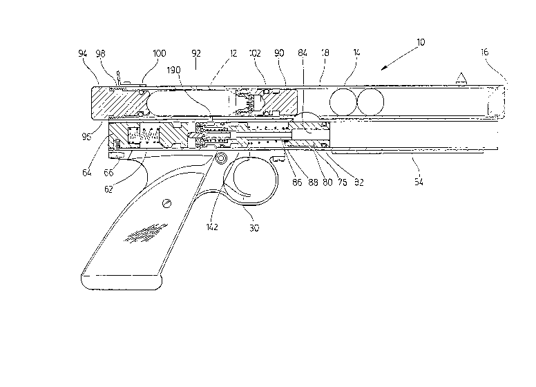
Figure 3 is a right side view of the ai. gun of
Figure 1, which view shows the upper and lower
barrels in axial cross section for purposes of
illustration;
Figure 4 is an axial cross section of the valve
body that is mounted in the lower barrel and the
components arranged therein;
Figure 5 is an axial cross section of the
punctu.re pin housing and the components mounted
therein; and
Figure ~ is a left side view of the upper and
lower barrels only showing the arrangement of the
holes and slots in the side thereof.

- 4
A completely assembled air or yas yun 10
constructed in accordance with the invention is shown
in Figure 1. The illustrated gun employs a C02
cylinder 12 indicated in dash lines in Figure 3 and
is adapted to fire paint pellets 14 of known
construction. The pellets can be inserted into the
front end of the gun by removing a magazine cap 16
which threads into the end of an upper barrel or tube
18. These pellets are able to drop individually into
a lower barrel 20 through an opening 22 in the upper
barrel. The gun is held by means of a gun handle 24,
the parts of which can be seen in Figure 2. An
optional rifle stock 26 can be attached by a suitable
bolt if desired.
The gun 10 is fired by means of the trigger
mechanisrn 28 which itself is of known construction
and therefore this mechanism will not be described in
detail except insofar as is required for purposes of
the invention. This trigger mechanism is available
from the Crossman Company located in Bloomingfield,
New York, U.S.A. The trigger mechanism includes the
trigger 30, a trigger enclosure 32 and a rigger
operated lever 34. In this mechanism the rear end of
the lever 34 is lowered by prassing the trigger 30
and then the lever rear end is pushed up after
release of the trigger by the spring 36. The lever

%~
-- 5
34 has an upstanding projection on its rear end wllich
engages in an annular groove 40 that extends about a
hammer 42 located in the lower barrel. It will thus
be understood how the hammer is released and the yun
is fired by pulling on the trigger 30.
The aforementioned gun handle 24 includes two
hand grip components 44, a cover 46 and a grip frame
48. The hand grips 44 are held in place by suitable
screws 50. A safety pin is provided at 52 just to
the rear of the trigger.
The gun 10 is loaded by pulling back on a
slidable pump member 54, the construction of which
can be seen clearly from Figure 2. The member 54
slides along the exterior oE the lower barrel 20 from
which the pellets are fired. The front section of
the pump member is preferably knurled as shown in
Figure 1 to permit it to be easily gripped while the
rear portion of this member is open at 56~ The pump
member 54 has an elongate slot 58 formed on its left
side as illustrated in Figure 1. A long pump screw
60 extends through the slot 58 and it ;s threaded
into an opening in the rear section of the
aforementioned hammer 42. The final rearward
movement of the pump member 54 will thus pull the
hammer 42 rearward against the pressure oE a hammer

z~
-- 6
spring 62 whicll is retained in the lower barrel by a
spring housing 64. The spring llousing 64 is secured
in the lower barrel by means o~ a set screw 66. This
set screw 66 also fastens the grip fra,ne 48 to the
lower barrel as illustrated in Fiyure 3.
rhe pump member 54 has a circular hole 70
located forwardly of the slot 58. Through this hole
extends a pump screw 72 which also exte,nds through an
elongate s]ot 74 formed in the side of the lower
barrel 20. The end of the screw 72 is threaded into
a bolt 76. In this way rearward movement of the pump
member will draw the bolt 76 rearwardly so that a
paint pellet 14 can drop through the opening 22 in
the upper barrel and through an opening 78 is the
lower barrel. ~hen the pump member moves forwardly
to its forwardmost position, the paint pellet in
front of the bolt is ready to be fired. The bolt 76
is generally cylindrical except for a flat side 80
positioned at the bottom. Mounted near the front end
of the bolt is a suitable O-ring 82 which seals a
small gap between the bolt and the inside of the
barrel when the bolt ;s in its forward position as
shown in Fiyure 3. The bolt has a central axial
hole or passageway 84 in order to receive a hollow
pin 86 described in more detail hereinafter.
Arranged about the pin 86 is a bolt spring 88 which
acts to push both the bolt and the attached pump member

28
-- 7
towards their forward position when the pump mernber
is releasedO Preferably the bolt spring is conical
so that it re~uires a minimum space when compressed.
The narrow end of the spring is arranged against the
rear surface of the bolt~
The preferred illustrated gun has means for
holding and punching a hole in the gas cylinder 12
and this includes a puncture pin housing 90
illustrated in detail in Figure 5. The cylinder 12
is inserted into a sealable compartment 92 in the
upper barrel, which compartment is closed by C02 cap
94. The cap 94 is formed with a knurled outer end 96
and threads 98 which engage threads formed on the
inside of the end of the upper barrel 18. The cap 94
is fitted with an O-ring seal 100 which effectively
seals the rear end of the compartment 92. The front
end of the compartment 92 is sealed by another O-ring
102 that extends around the housing 90.
Referring to Figure 5 of the drawings, the
housing 90 is formed with an annular groove 104
located a short distance forwardly of the seal 102.
The housing 90 is fixed in the upper barrel 18 by
means of two set screws 106. These extend through
two threaded holes 108 formed in opposite sides of
the upper barrel. It will be understood that the ends
of the set screws extend into the groove 104, thus

~2 E;~8
preventiny axial rnovement of the housing. The rear
section of the housing 90 has a slightly reduced
diameter at 108 and a small passayeway 110 opens into
this section of reduced diameter.
Threaded into the rear end of the housing 90 is
a generally cylindrical end piece 112 which has a
conical surface 114 that engages the compressed gas
cylinder. The member 112 has diametrically opposed
notches 116 to permit removal thereof from the
housing by means of a suitable tool. Located in the
housing 90 is an annular seal 120 and puncture pin
member 122 which is circular and formed with a small
central hole 124. The pin formed on this puncture
pin member punches a hole in the end of the gas
cylinder 12 causing compressed gas to flow through
the small hole 124 and out through the passageway 110
and into the compartment 92. Also located in the
housing 90 is a filter screen 126 that prevents any
foreign matter in the gas cylinder from passing into
the gas passageways and gas valve system of the gun.
The aforementioned magazine cap 16 has threads
130 which engage into threads on the inside of a
front end of the upper barrel. Also mounted on the
upper barrel are a front sight 13~ and a detachably
mounted rear sight 134. The rear sight is attached
by a small screw or screws 136.

g
The lower barrel 20 contains a gas valve systern
indicated generally at 140 in Figure 2. This systern
which is arranged in front of the hammer 42 includes
a valve body 142 fixedly located in the barrel and
111ustrated in detail in Figure 4O This valve body
has a gas chamber 144 therein and a forward gas
passageway 146 which is connected to the gas charnber
144 when the gun is fired. The passageway 146
extends through the aforementioned pin ~6 which is an
integral extension of the valve body. Extending
around the valve body is an annular groove 150. The
valve body is fixed in the lower barrel by means of
two set screws 152 which project into the groove
150. The screws 152 are threaded into two holes 154
located on opposite side of the lower barrel. There
is also a second annular groove 156 that extends
around the valve body and that forms part of a sealed
passageway leading to the gas chamber 144~ Another
part of this passageway is a radially extending hole
158 that opens into the groove 156. Mounted on
opposite sides of the groove 156 are two O-ring seals
160 and 162 that seal the gap between the valve body
and the interior of the barrel,
Means are provided for releasing compressed gas
from the chamber 144 and through the forward gas
passageway 146 to fire a pellet when the hammer is

~L26~8
-- 10
released. In particular there is a valve stem 164
wi~h a shoulder 166 formed thereon. A first hollow
portion of the valve stem extends though a valve
spring 168, which spring biases the valve stern in the
rearwards direction. A valve nut 170, preferably
made of brass closes the gas charnber 144. This nut
has external threads which engage threads formed in
the end of the valve body. The valve nut is
preferably recessed on its inside surface to
accommodate a nylon washer seal 172 which is engaged
by the shoulder portion of the valve stem. The valve
stem includes a solid second portion 174 that extends
through and out of a centre hole in the valve nut.
This solid second portion is struck by the hammer 42
when the gun is fired.
At the front end of gas chamber 144 is a steel
valve washer 176 against which one end of the spring
rests. Behind this washer is an O-ring seal 178
which rests against a shoulder 180 formed in the
valve body. It will be understood that the O-ring
seal seals the gap between the valve stem 164 and the
side of the gas chamber. Accordingly in order for
compressed gas to escape the chamber 144 it must pass
around the shoulder 166 of the valve stem and into
the central passageway of the valve stem. When the
valve body is installed in ~he lower barrel, the
aforementioned bolt spring 88 has one end resting

z~
-- 1 l --
against a front surface 180 of the valve body. This
bolt spring biases both the bolt and the pump to a
forward position so that it is not necessary to
manually pull the pump member back to its forward
position. Because of the central opening in the
bolt, lhe bolt is slidable along the hollow pin 86.
In order to permit compressed gas to pass from
the compartment 92 in the upper barrel and into the
groove 156, a hole 190 extending between the two
barrels is provided. This hole is located along a
portion of the upper barrel that holds the gas
cylinder and beside the valve body 142.
Various modifications and changes to the
described gas fired gun will be apparent to those
skilled in this art after considering the above
description. Accordingly all such modifications and
changes as Eall within the scope of the appended
claims are intended to be part of this invention.

Representative Drawing
A single figure which represents the drawing illustrating the invention.
Administrative Status

2024-08-01:As part of the Next Generation Patents (NGP) transition, the Canadian Patents Database (CPD) now contains a more detailed Event History, which replicates the Event Log of our new back-office solution.

Please note that "Inactive:" events refers to events no longer in use in our new back-office solution.

For a clearer understanding of the status of the application/patent presented on this page, the site Disclaimer , as well as the definitions for Patent , Event History , Maintenance Fee  and Payment History  should be consulted.

Event History

Description Date
Inactive: IPC deactivated 2016-01-16
Inactive: IPC assigned 2015-12-21
Inactive: First IPC assigned 2015-12-21
Inactive: IPC expired 2013-01-01
Inactive: Expired (old Act Patent) latest possible expiry date 2008-09-29
Inactive: Office letter 2007-01-12
Inactive: IPC from MCD 2006-03-11
Grant by Issuance 1990-01-02

Abandonment History

There is no abandonment history.

Fee History

Fee Type Anniversary Year Due Date Paid Date
MF (category 1, 8th anniv.) - standard 1998-01-02 1998-01-02
MF (category 1, 9th anniv.) - standard 1999-01-04 1998-12-16
MF (category 1, 10th anniv.) - standard 2000-01-04 1999-12-31
MF (category 1, 11th anniv.) - standard 2001-01-02 2000-12-19
MF (category 1, 12th anniv.) - standard 2002-01-02 2001-12-19
MF (category 1, 13th anniv.) - standard 2003-01-02 2003-01-02
MF (category 1, 14th anniv.) - standard 2004-01-02 2003-12-30
MF (category 1, 15th anniv.) - standard 2005-01-04 2004-12-31
MF (category 1, 16th anniv.) - standard 2006-01-03 2005-12-28
2006-12-28
Owners on Record

Note: Records showing the ownership history in alphabetical order.

Current Owners on Record
BRASS EAGLE INC.
Past Owners on Record
ALDO PERRONE
Past Owners that do not appear in the "Owners on Record" listing will appear in other documentation within the application.
Documents

To view selected files, please enter reCAPTCHA code :


To view images, click a link in the Document Description column. To download the documents, select one or more checkboxes in the first column and then click the "Download Selected in PDF format (Zip Archive)" or the "Download Selected as Single PDF" button.

List of published and non-published patent-specific documents on the CPD .

If you have any difficulty accessing content, you can call the Client Service Centre at 1-866-997-1936 or send them an e-mail at CIPO Client Service Centre.


Document
Description 
Date
(yyyy-mm-dd) 
Number of pages   Size of Image (KB) 
Drawings 1993-09-15 5 152
Claims 1993-09-15 5 130
Abstract 1993-09-15 1 21
Cover Page 1993-09-15 1 12
Descriptions 1993-09-15 11 278
Representative drawing 2001-06-29 1 26
Fees 2003-01-02 2 70
Fees 2003-12-30 2 63
Fees 1999-12-31 1 51
Fees 1998-01-02 1 56
Fees 2004-12-31 2 60
Fees 2005-12-28 1 31
Correspondence 2007-01-12 1 16
Fees 2006-12-28 1 25
Fees 1999-12-31 1 61
Fees 1998-01-02 1 52
Fees 1995-12-22 1 46
Fees 1996-12-30 1 54
Fees 1994-12-28 1 48
Fees 1993-12-14 1 43
Fees 1992-12-11 1 36
Fees 1991-12-11 1 32
Correspondence 1989-10-11 2 64