Note: Descriptions are shown in the official language in which they were submitted.
XF34
OSTOMY APPLIANCE
Background of_the Inv~ntion
This invention relates to an ostomy
appliance; pad for same; attachment means for
same; and kit of parts for assembling same.
In a successful known system, described and
illustrated in British Patent No. 1 571 657, an
ostomy bag is attached to a skin-compatible
medical grade adhesive pad by a releasable
coupling. In the case of some ostomates, however,
it may be desirable to provide a lightweight,
simple adhesive attachment system.
According to the present invention, there
is provided an ostomy appliance comprising a
body-attachable pad of skin-compatible adhesive
material having a stomal orifice, and means
whereby a plurality of ostomy bags can be attached
in sequence to the pad by exposing a fresh region
of adhesive each time it is desired to attach a
clean ostomy bag.
According to one embodiment of the invention
there is provided an ostomy appliance comprising a
bay for receiving discharged wastes, a stomal
orifice in one wall of the bag, a flange having a
flat surface, intended to face towards the body of
the wearer when the appliance is worn, surrounding
the orifice, a medical grade adhesive pad, and a
r3~,
3~
XF3
--2--
plurality of double sided adh sive annuli,
separated ~y peelable cover annuli carried by the
pad, each of the double sided adhesive annuli
having a peripherally projecting portion.
The double-sided adhesive annuli are intended
~or sequential use in attaching the bag, via its
flange, to a pad of medical ~rade adhesive material
which the wearer has attached to his (or her) skin
at the peristomal region. The reason for having a
plurality of adhesive layers separated by peelable
cover annuli is so that a new double sided annulus
can be exposed by peeling off the outer cover
layer. Hence each time a bag is emptied or changed
it can be securely reattached to the medical grade
adhesive pad and there is no need to frequently
remove the pad. This is a considerable advantage
in that the operation of removing and replacing
such a pad is one of some difficulty and is often
painful.
Such an appliance can be used as a 4-day bag
or a 5-day bag by providing a corresponding number
of double sided adhesive annuli. Each cover layer
may have a radially projecting finger tab which
serves two purposes, firstly it can carry a number
or indication (e.g. "Monday") and secondly it
enables the cover layer to be readily stripped off
to expose the adhesive surface of the underlying
double sided adhesive layer so that the flat
surface of the flange on the bag can be brought
into face-to-face contact with the so exposed
adhesive surface.
In accordance with one preferred embodiment
of the invPntion, an ostomy bag is attached to a
body-attachable pad by a series of sequentially
peelable adhesive members each of which has a
XF34
--3--
grasping tab. A flexible microporous layer or tape
may be used to assist in attaching the pad to the
skin of ~he wearer. In one embodiment the tabs are
arranged so that peeling off a first tab exposes a
second tab, the latter not being accessible to the
user until the first tab has been peeled off. In
another embodiment the tabs are radially extending
and angularly spaced apart from tabs of adjacent
adhesive numbers.
Alternatively, double sided adhesive layers
may be alternated with peelable cover layers, and
the cover layers may be shaped and arranged so that
they are se~uentially peelable, that is to say,
each cover layer has a grasping tab and these tabs
are so arranged that peeling off one tab exposes an
underlying tab. Each cover layer is peeled off
when it is desired to expose a fresh region of
adhesive in order to attach a clean bag to the pad
of skin-compatible material wh:ich is adhesively
~0 attached to the peristomal region.
In accordance with another preferred
embodiment of the invention, there is provided a
body-attachable pad carrying a flange to which is
adhesively secured a stack of sequentially peelable
adhesive members for attaching an ostomy bag to the
flange, and the flange and the pad are connected by
a flexible web which permits limited relative
movement therebetween in a direction substantially
perpendicular to the pad. Using such an
arrangement, an ostomate can place his/her fingers
behind the flange (i.e. between the flange and his
body) so as to absorb the pressure which is applied
to fi~ the bag to the exposed one of the stack of
plasters.
In accordance with a further alternative
~L26~
XF34
embodiment of the invention, a kit of parts for
making an ostomy appliance includes an apertured
pad of body-attachable, skin-compatible material,
and a plurality of ostomy bags to each of which i5
attached a peelable cover layer which when removed
exposes an annular region of adhesive surrounding a
stomal orifice in a wall of the bag, the said
region of adhesive being arranged in use to
adhesively secure each bag in turn to the pad.
In ascordance with yet another preferred
embodiment of the present invention, the
body-attachable, skin~compatible pad is attached to
a disc of plastics material (e.g. a vacuum-formable
material) having an upstanding rim, there being a
closed loop line of weakening within the rim so
that a central region of the disc can be manually
removed by the user. The aperture so produced
serves as a stoma aperture.
In use the user cuts or punctures a hole for
his stoma in the pad of skin compatible material
and removes the central area of the plastics
material; then when the member is applied to the
hody an inner marginal edge portion of the pad
takes up a position closely surrounding the stoma,
ana forms both a protective pad and a seal. The
skin-compatible material then covers the exposed,
inner edge of the disc and avoids any pain or
irritation being caused to the stoma by the inner
edge of the disc.
Also according to the invention an adhesive
plaster for use in attaching an ostomy bag to a
body-attachable member has an adhesive-protecting
cover layer which is constructed so that successive
separate regions of the cover-layer can be torn off
in turn, so exposing a fresh adhesive for the
3~
XF34
--5--
attachment of a fresh ostomy bag.
The invention will be better understood from
the following non-limiting description of examples
thereof given with reference to the accompanying
diagrammatic drawings in which:
Brief Descri~tion of the Drawinqs
FIG. 1 is an exploded perspective view o~ a
medical grade adhesive pad, a plurality of double
sided adhesive annuli, and intervening cover
annuli;
FIG. 2 is a side view corresponding to FIG.
l;
FIG. 3 is a side view of an alternative
embodiment of the invention;
FIG. 4 is a cross-sectional diagrammatic
view, somewhat enlarged from full size, of an
example of a body attachable member according to
the invention;
. FIG. 5 is a view similar to FIG. 4 showing
the member in position on a wearer and illustra-ting
the cushioning and sealing effect of a marginal
portion of the pad;
FIGS. 6 and 7 show, in cross-section and in
front elevation respectively, one embodiment of a
skin-compatible medical grade adhesive pad carrying
a plurality of "peel off" adhesive annuli;
FIGS. 8 and 9 show, in cross-section and in
front elevation respectively, a second embodiment
of a pad carrying a diferent arrangement of "peel
off" adhesive annuli;
FIGS. lO and 11 show, in cross-section and in
front elevation respectively, a third embodiment of
pad carrying yet another arrangement of "peel off"
adhesive annulii
3~
~F34
--6--
FIG. 12 diagrammatically shows a further
em~odiment of a body-attachable pad together with
an ostomy bag;
FIG. 13 is an exploded view illustrating
another embodiment of the invention;
FIG. 14 is a cross-section taken in a
vertical plane through the adhesive plaster shown
in FIG. 13 with the thickness exaggerated for
clarity of lllustration;
FIGS. 15 and 16 illustrate another manner of
use of a plaster according to the invention, FIG.
15 being a cross~sectional view taken in a vertical
plane and FIG. 16 is a front view of a plaster
applied to a body-attachable member.
FIG. 17 is an exploded perspective view of a
medical grade adhesive pad, a porous adhesiv~
layer, and a plurality of peelable adhesive members
with angularly offset projecting tabs.
FIG. 18 is a front elevational view o~ one of
the peelable adhesive members of FIG. 17.
FIGS. 19, 20 and 21 illustrate a tapered or
angled rib feature of one embodiment of the present
invention, FIG. 19 being a front view, FIG. 20 a
vertical axial cross-section, and FIG. 21 being an
enlargement of part of FIG. 20;
FIGS. 22 and 23 are front view and vertical
axial cross-sections of an embodiment of the
invention wherein a marginal portion of the bag
wall surrounding the stomal aperture acts as a
wiper to wipe the peripheral rib of the
body-attachable flange.
FIGS. 24 and 25 are like views respectively
of a washer or flange for attachment to an ostomy
bag to render it highly suitable for use as a
peel~off bag;
3f~
XF34
--7--
FIG. 26 is an enlargement for clarity of part
of FIG. 25; and
FIGS. 27 and 28 are a front view and a
vertical axial cross-section, respectively, of an
S ostomy appliance and bag illustrating a stack of
peelable adhesive members and a tapered rim on a
peripheral rib of the body side flange.
In the drawings, like parts bear like
reference numerals.
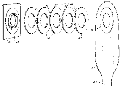
Referring Eirstly to FIGS. 1 and 2, the
illustrated ostomy appliance includes a medical
grade adhesive pad 10 and an ostomy bag 12. The
ostomy bag has a stomal orifice 14 which is
surrounded by a flange, e.g. of synthetic plastics
material, having an annular flat surface which is
intended to face towards the body of the weaxer
when the appliance is in use. This surface is
indicated at 16. The medical grade adhesive pad 10
also has secured thereto a flange 20 which
optionally includes an inner peripheral rib 22.
The flange 20 has an outwardly facing flat annular
surface 24, intended to receive a stack of double
sided adhesive annuli which are interleaved with
annular cover layers. The medical grade adhesive
pad 10 may be bonded to a plastics film layer 26,
in conventional manner. In use, a hole indicated
by the dotted lines 28 is cut in the pad 10 and the
film 26 so that the user's stoma can be passed
therethrough.
Suitable medical grade adhesives comprise
pressure sensitive adhesive formulations that
consist of a homogeneous blend of one or more water
soluble or water swellable hydrocolloids dispersed
XF34
--8--
in a viscous elastomeric substance such as
polyisobutylene as disclosed by Chen in United
States Patent 3,339,506. Optionally, the
adhesive composition can also include one or more
cohesive strengthening agents described by Chen et
al. in U.S. patent 4,192,785 or one or more
hydratable natural or synthetic polymers as
described by Pawelchak et al. in U.S. patent
4,393,080. Other medical grade adhesives designed
for ostomates and available on the market are also
suitable.
The double-sided adhesive annuli are
indicated at 32, and for example, five are here
shown. This would be appropriate for a 5-day
ostomy appliance. The fifth one in order of use is
directly adhesively attached by one of its adhesive
surfaces to the surface 24 and by its other surface
to a peelable annular cover layer 34. Like cover
layers are located between adjacent double sided
adhesive annuli, and these cover layers as seen
best in FIG. 1 each have a radially projecting
finger tab 36 useful firstly for peeling off the
layer 34 and secondly for carrying a numeral or
other visible indication to assist the user of the
appliance.
The bag 12 may be either a bag having a drain
outlet 40 as seen in FIG. 1, or may alternatively
be a closed bag intended to be thrown away when
full, as seen in FIG. 2.
The words "annulus" and "annuli" are used in
the application without a strict geometrical
meaning. That is to say, a double sided annulus as
used in this invention need not be geometrically
circular; a double sided adhesive layer of any
shape which surrounds the stomal orifice and which
~2~3f~
XF34
_g
can be peeled off from an adjacent layer to expose
a region of adhesive would be suitable.
Referring now to FIG. 3, the ostomy bag 12
and medical grade adhesive pad 10 axe as shown
previously. The double sided adhesive annuli
interleaved wi~h peelable cover annuli however have
a gradually diminishing outside diameter as one
moves from the first to be used (nearest to the
bag) to the last to be used ~nearest to the pad).
The reason for this is to ensure that when one
peelable cover layer (e.g. 34A) is removed, it
exposes an area of fresh adhesive on the double
sided adhesive annulus 32A, and then when the next
cover layer 34B is removed, a fresh layer of
adhesive on theiannulus 32B is exposed.
Deterioration of the outer edges of the adhesive
annuli is thereby minimized.
Another feature of difference compared to the
FIGS. 1 and 2 embodiment is that the outer diameter of
the adhesive layers is greater than that of the cover
layers (except for th~ peel tabs thereof).
Consequently narrow outer rims of the adjacent
adhesive annuli tend to stick together and prevent
any peel apart occurring except at the surface
where -the outermost peel-off cover annulus is being
removed.
Referring now to FIGS. 4 and 5, a
body-attachable member or pad 40 comprises a pad 42
of medical grade skin compatible adhesive fixed to
a disc 44 of plastics material. The disc 44 has an
upstanding rim 46, and a closed loop line of
weakening, which may be circular, indicated at 48
to define an area within the rim 46 which can
readily be removed by a user without the use of a
tool.
3~
XF34
--10--
A s-trippable protective layer 50 is applied
to the rear surface of the pad 52. This layer 50
is stripped off to expose an adhesive surface of
the pad 52 when the pad 40 is to be applied to the
patient's body.
FIG. 5 illustrates the member 40 in position,
the skin of the patient being indicated at 52 and
the stoma of the patient at 54. As will be seen,
the inner marginal edge portion 56 of the pad 42
has been deformed somewhat so that it closely
surrounds and is in contact with the periphery of
the patient's stoma 54; this provides a cushioning
effect preventing the relatively sharp inner rim 58
of the disc 44 from painfully digging into the
patient's stoma, and moreover the good adhesive
contact between the pad 42 and the stoma 54
provides a sealing effect preventing any migration
of liquid waste products towards the peristomal
skin area 52. The annular surface 60 of the disc
14 serves for adhesive attachment of an ostomy bag
in any of the various ways described in this patent
application.
In a preferred form of the present invention,
the rim 46 is produced by vacuum forming.
~ larye number of body attachable members can be
readily produced withou~ the need for individual
molding of plastics disks having rim parts.
An alternative embodiment of the present
invention is illustrated in FIGS. 6 and 7. As seen
i~ FIGS 6 and 7, a ~ad 70 of skin-compatible
medical grade adhesive material such as that
described above, and carrying a strippable rear
3~
XF34
--11--
cover layer 72 supports a front cover sheet 74
whose function is -to cover over the edges 76 of the
pad 70 which would otherwise be exposed, there
being a strippable annular paper or like layer 78
which protects adhesive on the rear surface ~left
hand side as seen in FIG. 6) of the protective
layer 74 where this extends beyond the pad 70. As
illustrated, the pad 70 is in the form of a flat
disc and the protective layer 74 is substantially
rectangular. Attached to the pad 70 is a plastics
disc 82 carrying a central circular rim 84 which
defines a stomal aperture 86. The disc 82 carries,
stacked over the layer 74, a stackPd pile of
annular adhesive attachment members, herein called
plasters, each plaster being constituted by a layer
of tough paper or flexible plastics film bearing
adhesive 85 and having a grippable tab 92. The tab
arrangement as illustrated in FIG. 6 is such that
the rearmost plaster has the largest tab and the
forwardmost plaster has a relatively small tab as
seen at 94.~ The assembly is pro-tected by a front
cover annular layer of release paper or other
suitable material which is identified at 98.
It will be seen that by peeling off firstly
the cover layer, an annular region of adhesive is
ex~osed to which an ostomy bag may be applied, and
after that bag has been filled, then by peeling off
the first adhesive plaster 94 further fresh
adhesive on the so-exposed face of the next
underlying plaster is made available for attaching
a subse~uent ostomy bag to the appliance.
E'IGS. 8 and 9 show an alternative version of
this embodiment of the invention, the difference
being that in this embodiment the tabs of the
adhesive plasters 100 are all of the same size. As
3~
XF34
-12-
seen in FIGS. 8 and 9, no adhesive is provided
between the plasters outside the annular region, so
that one tab can readily be separated from the next
and so that the cover sheet 102 can be removed at
the beginning of the use of the appliance.
Another variation of this embodiment of the
invention is illustrated in FIGS. 10 and 11.
According to this advantageous version, each of the
cover layers 106 and the plasters 108 is annular in
form with an upwardly projecting tab, the tab being
denoted 110 in the case of the cover layer and 112
for each of the plasters. Each of the plasters has
a tab of progressively increasing height, moving
from the plaster closest to the disc 82 to the
plaster furthest from the disc 8~. Moreover, each
tab has an elongated slot cut therein, near to the
top of the tab, to enable a user to insert his
Æingernail in the slots so as to more readily
separate one tab from the next. The slot in the
cover layer is indicated at 114 and the aperture in
the Eront tab 112 is indicated at 116. For
simplicity of illustration in FIG. 11, the other
apertures in the tabs 108 are not shown.
Referring to the versions of the inventio~
shown in FIGS. 6 11, it will be realized that any
convenient numbers of separate plasters may be
employed. Although five plasters have been
illustrated in FIG. 6, and four plasters in FIGS. 8
and 10, any selected number of plasters, e.g. one
for each day of the wee~, can be included in t~e
appliance. Moreover, while in some instances it
may be preferable for the ostomy bag which is to be
used with the illustrated appliances to have a
relatively stiff plastics flange surrounding the
stomal orifice in one of its walls, in other
~2~
-13- XF34
instances no such stiff flange would be needed and
the bag wall could be adhesively secured directly
to the exposed adhesive surface.
An alternative embodiment of the invention is
shown in FIG. 12, which is a diagrammatic
cross-section illustrating the skin 120 of a wearer
with a body-attachabIe pad 122 of medical grade
adhesive material such as that referred to above.
The stoma of the patient is seen at 124, projecting
through a suitable hole in the pad 122. A disc 126
carrying a circular rim 128 is connected to the pad
122 by a flexible annular sheet 130. The sheet 130
may be of fabric or of a thin flexible plastics
film.
The disc 126 carries a stack of annular
plasters 132, each of which has a tab 134. A
strippable protective front cover layer 136
protects the adhesive 138 on the outermost plas-ter.
An ostomy bag 140 having a stomal aperture 142
surrounded by a flat thin pla-te of annular form 144
cooperates with the body-attachable appliance
including the pad 122. In use, the protective
layer 136 is stripped off exposing the adhesive
layer 138 and the bag is brought in face to face
manner up against this adhesive, the rim 1~8 then
extending just within the confines of the stomal
orifice 142. The bag is consequently held firmly
in position on the disc 12h and during the
assembly, the user can if he wishes place his
fingers behind the disc 126 to support the disc 126
against the pressure needed to press the plate 144
onto the adhesive 138. When the bag 140 is full,
it is removed, the used plaster is also removed so
exposing a fresh adhesive surface on the plaster
beneath. A new bag can then be applied in a
~z~
XF34
-14-
similar way.
The illustrated adhesive plaster 210 (FIGS.
13 and 14) includes a substrate 212 (which may for
example be a conventional fabric substrate as found
in conventional sticking plasters) having a central
hole 214 therein to constitute a stomal aperture.
The rear (body side) surface of the substrate
carries adhesive 216 whereby the plaster can be
fixed to a body-at-tachable member 218, not sho~m in
FIG. 14. The front (or bag side) surface carries
adhesive 220 which is covered by a peelable
protective layer 222. The layer 222 is divided
into five annular regions 222a to 222e by circular
partial cuts 224 which extend through, for example,
about 3/4 of the thickness o the protective layer
222. These cuts may be made by a punching or
stamping operation. Alternatively the cuts may
extend completely through the layer 222, or lines
of weakening may be producefl by having rows of
perforations. Other expedients will occur to a man
of average skill in the art.
While a circular hole 214 and circular cuts
224 have been described, it will be appreciated
that a non-circular, e.g. oval, configuration could
be employed although circular is preferred.
In use of the assembled appliance, an
intervening member ~30 herein called a chute member
is fixed to a body-attachable pad 218 of medical
grade adhesive and the cylindrical wall 230a of the
chute is passed through the hole 214, the latter
being of a sufficient size to accommodate the
chute. The chute functions to guide any waste
products issuing from the stoma into the interior
of an ostomy bag and to minimize the chance of any
of them coming into contact with the adhesive 216
~2Çi~
XF34
--15--
or the adhesive 220. If such contact were to
occur, the security of attachment provided by the
adhesive would be made less reliable. However, in
some instances, e.g. when a very simple and
inexpensive ostomy system is desired, the chute 230
can be omitted and the plas-ter 10 attached directly
by the adhesive 216 to the pad 218.
In use, the inner ring 222a is peeled or
stripped off, so exposing an annular area of
adhesive 220, and the wall of an ostomy bag having
a stomal orifice therein is brought in face to face
contact with the exposed area of adhesive 220, with
the stomal orifice in the bag wall substantially in
registry with the hole 214. To facilitate
stripping off the rings 222a to 222e, each ring may
carry a tab or projection 32 which can be grasped
between finger and thumb. The tabs may if desired
by numbered as shown in FIG. 13.
The ostomy bag employed may be of the ~ind
which has a flat annular flange on its rear wall
surrounding the stomal orifice therein, or such a
flange may be omitted and the bag rear wall
directly applied to the adhesive 220.
The intermediate member 230 may
advantageously be made by vacuum forming a
synthetic plastics film, and its flange 230b is
preferably ultrasonically welded to a plastics film
forming the outer surface boundary of the pad 218.
In an advantageous embodiment of the.
invention, the adhesive 216 may be such as to have
a higher "peel strength" than the adhesive 220.
This ensures that the attachment of the plaster 210
to the pad 18 remains secure when force is applied
to peel off one of the rings 222a to 222e.
FIG. 15 illustrates a body-attachable medical
XF34
-16-
grade skin-adherable pad 240 which is disc-shaped
with a central hole 241, i.e. is annular in shape.
To the pad 240 is attached a vacuum formed plastics
rim 242. An adhesive plaster 244 according to the
1nvention is directly fixed in any suitable ~lay,
e.g. by adhesive, to the front face 246 of the pad
240. The plaster 240, 242 has a central hole 248
of a diameter slightly greater than the outer diameter
of the rim 242. A protect-ve layer 250 can b~ manually
p~eled or stripped from the plaster 244. The layer
250 is separated by cuts 252 into concentric rings
250a to 250d (FIG. 15). Each of these rings can be
separately stripped from the plaster 244. While
the plas~er 244 and pad 240 are shown as circular
~ 15 in shape, they could have other configurations.
The pad 218 or the pad 240 may be made of a
medical grade adhesive as described above.
An advantageous form of body-attachable pad
consists of three layers, namely a skin compatible
medical grade adhesive, a plastics film thereon,
and a Fasson fabric plaster layer covering the film
and having its marginal edge portions extending
somewhat beyond the outer edges of the adhesive and
the film. The adhesive and the film will normally
be coextensive. The purpose of the Fasson fabric
layer is to shield the edges of the adhesive so
that, for example, these edges do not slide to the
clothing of the wearer.
Referring now to FIG. 17, an alternative
embodiment of the present invention ostomy
appliance of FIGS. 1 and 2 is shown in exploded
view. The ostomy appliance includes a flexible
microporous tape designated generally 1750 having
an aperture 1751 therethrough to accommodate rib
22. The diameter of the aperture 1751 is larger
-17- XF34
than the diameter of rib 22 but smaller than the
diameter of flange 20. Tape 1750 comprises
adhesive layer 1752 that overlaps flange 20 and any
of plastics film 26' not affixed to flange 20.
Outer surface 1754 of the microporous tape is a
porous backing layer.
In FIG. 17, tape 1750 is larger in area than
pad 10' and square or rectangular in shape. In use
adhesive surface 1752 is pressed onto the body a
distance from the stoma and aids the adhesive pad
10' in maintaining the ostomy appliance in place.
Medical adhesive pad 10' and plastics film layer
26' are the same as pad 10 and layer 26 of FIG. 1
except they are circular in shape and generally
smaller in area~
The term microporous is used in connection
with adhesive layer 1752 because layer 1752 appears
to be continuous but when viewed under a microscope
it is sponge-like having randomly located ahannels
and voids. The layer 31 can be of the acrylic type
as taught by Copeland in U.S. patent 3,121,021, or
it can be made of the same ingredients as pad 10
with the microporosity resulting from a difference
in processing. See European Patent Application
A1 0081 9~7. This m.icroporous tape can also be
employed as adhesive layer 74 in the embodiment
shown in FIGS. 6 to 11.
Porous backing layer 1754 can be formed of
woven or non-woven fabric such as the rayon web
described by Copeland in U.S. Patent 3,121,021, an
open mesh polymeric substance such as an open mesh
polyethylene or polypropylene or a polymeric foam
such as polyurethane foam, polyethylene foam, etc.,
or a non-woven material made from polyester fibers,
polypropylene fibers, nylon fibers, composite
~ 3~ XF34
-18-
olefin fibers, or cellulose fibers which are
cornmercially available.
The tape 1750 while aiding in attaching the
ostomy appliance to the user is flexible and allows
the skin to breathe resulting in a more comfortable
attachment.
Tape 1750 is affixed to the flange surface 24
not only by its own adhesive layer 1752 but also by
an overlapping member 1758 such as a plastics film
having an adhesive layer on each side. Member 1758
has an aperture 1759 therethrough which is slightly
larger then the diameter of rib 22. The outer
diameter of member 1758 is larger than the aperture
1751 in tape 1750. Member 1758 overlaps both a
portion of flange 20 adjacent rib 22 and a portion
of side 1754 of tape 1750.
In FIG. 17, the peelable adhesive members are
indicated at 1760, and for example, five are shown,
1760A to 1760E. Each member comprises a layer of
tough paper or flexible plastics film bearing an
adhesive layer 1762 and having a grippable tab
1764. The tab arrangement is such that each is
angularly displaced from the tab of an adjacent
member around the common axis of the members 1760.
The fifth peelable adhesive member 1760E, the last
in order of use (i.e. the one nearest the member
1758), is directly adhesively attached to the
outwardly facing adhesive surface of member 1758.
It will be remembered that member 1758 comprises a
double adhesive layer, one on each side thereof.
The non-adhesive surfaces of each of the remaining
members (those surfaces which face pad 10') are
attached to the adhesive surface 1762 of the
previous member which faces the surface 16 of bag
12.
XF34
19-
The oukermost peelable member 1760A, the
flrst one to be used, has attached thereto a
suitable protection cover layer 1770 which protects
the outer adhesive layer 1762 of -the first member
1760A until use.
FIG. 18 is a front elevational view of a
member 1800 suitable for use as member 1760 in FIG.
17 but showing in more detail an alternative
embodiment of tab 1762. The member 1800 preferably
is made of a clear flexible plastics film with one
surface such as the outward facing surface 1802
coated with an adhesive. The member 1800 further
comprises a circularly shaped grippable tab portion
1804 having an opening 1806 therethrough. The tab
is large enough to be easily gripped by the
wearer 15 fingers and the opening 1806 assists
therein.
FIGS. 19-21 illustrate an alternative design
of a flange member for attachment to the me~ical
gxade adhesive pad 10 illustrated in FIG. 1. This
flange member 1920, like the flange member 20 of
FIG. 1, has an inner peripheral rib 1922. In order
to provide a "lead-in" when a user is attaching a
bag to an exposed adhesive surface of one of the
peelable adhesive members, the inner end, that is
to say the end of the rib which extends towards the
ostomy bag when the ostomy bag is being applied and
which extends into the ostomy bag when it is
secured, it canted inwardly as seen best in FIG. 21
at 1923. Consequently, a tapered annular outer
surface 1925 is provided which assists a wearer of
a hag in bringing the stomal orifice of the bag
properly into registry with the flange member 1920.
In another embodiment of the invention, there
are provided seven peelable adhesive members which
L3~
XF34
-20-
may for example be numbered 1-7, and may be
arranged in the manner illustrated in FIG. 22.
Referring to FIGS. 22 and 23, a medical adhesive
pad is shown at 2310, -the flange thereon at 2320,
and a layer of self adhesive fabric 2321 is placed
over the flange 2320 beneath the base of the stack
of peelable adhesive members 2323.
A flat annular plastics washer 2325 is
secured to a wall 2327 of an ostomy bag whose other
wall is seen at 2329. The flat annular washer 2325
may be of plastics material and is constructed so
that it has a central circular oriflce whose
diameter is som~what greater than the outside
diameter of the substantially cylindrical rib wall
2322. The material of the bag wall 2327 however
extends inwardly of the inner edge of the washer
2325, and in use acts to wipe against the outside
wall of the rib 2322 so tending to keep this
outside wall clean of waste materials. It will be
appreciated that because the diameter of the stomal
orifice in the washer 2325 is greater than the
outside diameter of the rib wall 2322, applying the
bag to the flange does not require a careful and
"fiddy" adjustment of relative positions.
Instead of utilizing a plain, flat annular
washer such as 2325 shown in FIG. 23, one may
instead emply a washer for attachment to an ostomy
bag of the form shown in FIGS. 24 and 25. This
washer may for example be of ethylene vinyl acetate
polymer and, referring to FIGS. 24-26, is attached
to an ostomy bag surrounding the stomal aperture
~hereof, the bag being show at 2510. The washer
2512 has one annular flat surface 2514 intended for
presentation to the exposed adhesive of one of the
peelable adhesive members. There is a beading 2516
y~
XF34
-21-
at the outer rim of the washer 2512. The inner
margin of the stomal aperture 2518 in the washer
2512 is formed by a flexible deflectable seal strip
2520 formlng part of the washer 2512. This seal
strip 2520 serves a similar function to the innPr
por-tion 2331 of the bag wall 2327 (FIG. 23~ in that
it assists in wiping waste material clear of the
cylindrical rib portion of a flange such as flange
2320. Equally, it would act similarly in relation
to the external cylindrical surface of the rib 1922
illustrated in FIG. 20.
FIGS. 27 and 28 illustrate a flange 2720
which is substantially in accordance with the
design illustrated in FIGS. 19-21 assembled in
conjuction with an ostomy bag 2722 and a medical
grade adhesive pad 2724. The bag 2722 is of course
not shown in FIG. 27, and the arrangement of
peelable adhesive members is similax in broad
concept to that illustrated in FIG. 6 of the
present patent application.
While there have been suggestions in the
past, e.g. in British Patent Specification No.
l 256 866, tha-t an ostomy bag can be attached to a
body-attachable ring by adhesive, there has been
(to the best of Applicants' knowledge and belief)
no means hitherto suggested or.obtainable other
than recent patent applications of the present
Applicant whereby a series of ostomy bags can be
adhesively attached in turn to a single
body-attachable member, while the member remains
attached to the body of the wearer.
Moreover, the arrangement according to the
invention is light in weight, has a very flat
configuration, does not produce an unsightly bulge
under the clothes, and is easily and inexpensively
manufactured.