Note: Descriptions are shown in the official language in which they were submitted.
~l2~ 8~
I`itle of the Invention
llabel Printer
1 Field of the Invention and Related Art Statement
This invention relates -to a label printer for
printing a predetermined matter on a label and issuin~
the label after printing, and more partioularly to a
label printer which inoludes two independen-l; printing
devices therein.
Label printers which include two differenl printing
devices therein have been already provided. One of the
t~o printin~ devices is provided for printind on a label
while the other printing device is provided for printing
on record paper in the form of a web SllCh as a reoeipt
or a journal paper. Label printers oi` such a
construction eliminate the necessity to exchan~e, in
use, an object for printing such as a label each time
the object for printing is to be altered. For example,
~hen a receipt is to be printed just after a label has
been printed, it is not necessary to load the receipt
instead of the labe~. This is convenient for an
operatar and will quicl~en intended printin~.
Now, problems of such prior ar-~ wlll be des¢ribed.
Now -that a label printer inoludes two independent
,
'
1 printing devices, naturally it also includes tl~O
independent objeo-ts for printing such as a label and
record paper. Normally, those objects for printing are
each held in the form of a roll. ~lowever, those ohJects
for printing have a lar~e volume and thus OCCI3py a wide
space within tbe printer. Accordin~ly, it is a draw~acl~
that the si.~ze of the entire printer must be lar~e
aocordin~ly.
~leanwhile, separate motors are provided ~or -the
individual prin-ting devices as means for ;.ndependent].y
driving the printing deYices. Accordingly, lt is also a
drawback that the number of motors is large and a motion
transmitting meohanism is complica-ted. Besi.des, such a
Large number of motors and the motion transmitting
mechanism of such a complica-ted structure will further
increase the overall size of the printer.
Objects ar~d Summary of the Invention
It is a first object of the present invention to
provide a label printer of the type including tl~o
printin~ devices wherein the overa].l size thereof can be
reduced.
It is a seoond object of the i.nvention to provide a
label printe:r of the type including two printin~ devices
1 wherein contents of printing on print ~edia such as a
label or record paper can be observed in a natural
posture of an operator when thley are issued.
It is a third object of the invention to provide a
label printer of the -type incl~ding two printing devices
- wherein a mechanism for transmitting a motion to the
printin~ devices can be simplified.
Xn order to attain the objec-ts, according to one
aspect of the present invention, there i.s provi.ded a
label printer which comprises a first.pri.nting device
includin~ a ~irst print head mounted for IJp and down
pivotal motion and for engagement with an upper face of
a first plat~n, a second printing device located withi.n
a same verti~al plane below said firs-t printin~ device
and includin~ a second print head mounted -for up ànd
down pivotal motion and for engagement with a lower face
of a second platen, a first supply means located behind
said first printing device for holding ground paper in
the form of a roll to which a large number of labels are
applied and for supplying -the ground paper ko said first .
printing device with the labels directed ~pwardly, and a
second supply means for holdin~ elongated record paper
in the`form of a roll with a printing face thereof
directed outwardly and for supplyin~ the record paper to
~L~6~
l said second printing device with the printing f'ace of
the record paper directed downwardly.
Thus, the overall si~e of -the printer can be
reduced for the reasons that the first and second
printing devices are located w:ithin the same vertical
p].ane, that t.he two printin~ devices can be located near
to eaoh o-ther, and that the location of the first supply
means will not interfere with locations of any o-ther
components of' the pr.in-ter. Besi~es, a label and record
- 10 paper are issued at locations near to each other with
printed faces thereof directed to the front. Since
record paper is held in -the form of a roll at the second
- supply means, it is provided with a curling habit which
turns, when l;he reoord paper is to be issued, the record
paper upwardly to direct the printéd faoe of the same to
the ~ront after it has passed the second printing
device. Accordingly, an operator can observe contents
of printing c)n the label and the record paper in a
natural posture.
Further~ accordin~ to another aspect of the present
i.nvention, two one-way olutches for transmit-ting
rotation in opposite directions are provi.ded, whereby
two printing devices are alternately driven by a
bidirectional motor via the one-way clutches. In this
,
9~ ,
1 arrangell~ent, a mechanism for transmit-ting a motion to
tlle printing devices can be simplified. Particularly
where -the t~o one-way clutches are disposed in a coaxial
relationship with a rotary shaf-t of the motor, the
motion transmittin~ mechanism can be Eurther simplified
and -the overall size of the printer can be reduced
accordingly.
Brie~ ~escription of the Drawings
Fig. 1 is a perspective view of an entire pril-lter
illustrating a prefelred embodiment of the presen-t
invention;
Fig. 2 is a side elevational viel~ of the printer of
Fig. l;
Fig. 3 is a side elevational view illustrating a
motion transmitting route for driving a firs-t platen and
a -tal~e-up shaft; and
Fig. 4 is a side elevational vie~ illus-trating
another motion transmitting rou-te for driving a second
platen.
Description of the Preferred Embodiment
Now, a preferred embodiment of the present
inven-tion will be described with reEerence to the
~2~
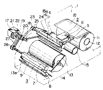
1 accompanying drawings. The printer shown include.s a
frame 1 in the form of a housing. A first printin~
device 2 and a second printing device 3 are located
wi-thin the frame 1 such -that the first printin~ device 2
is located above the second printin~ devioe 3 within a
same vertical. plane. The first p:rinting device 2
includes a fi.rst platen 4 and a first thermal head 6
l~tliCh serves as a first print head. Tlle fi.rs-t therma].
head 6 is mounted for Up and dow~pivotal rnotion on a
support shaft; 5 and normally contacts wi.th an upper face
of the first platen 4. Thus, the first therma]. head 6
can be pivoted upwardly away from the first platen 4.
~leanwhi.le, the second printing device 3 includes a
second platen 7 and a second thermal head 9 whi.ch serves
as a second print head. The second thermal head 9 is
mounted for llp and down pivotal motion on a support
shaft B and normally contacts.with a lower face of the
second platen 7. Thus, the seoond thermal head 9 can be
pivoted down~ardly away from the second platen 7.
A supply shaft 12 servin~ as a firs-t supply device
is l.ocated behind the first prin-ting device 2 and is
mounted for rotation on the frame 1. Elon~ated ~round
paper 11 in the form of a roll is carried on the suppl.y
shaft 12 and has a large number of labels 10 a~plied in
'
1 an equidistan-tly spaced relationship thereto.
~leanwhile, an upwardly open hopper 14 servi.ng as a
second supply device is fixedly loca-ted between the
first and second printing deY.ices 2 and 3. Elongated
record paper 13 in the form of a wound roll is placed on
the hopper 14 with a printing face 13a thereof directed
ou-twardly.
Meanwhile, a label exfoliating member 16 for
bending the ground paper 11 a-t an aoute angle to
exfoliate a label 1~ f'rom the ground paper 1.1 i.s located
forwardly of the firs-t platen 4. The label exfoliating
member 16 is secure~d to the frame 1.
A take-lp shaf', 15 is supported for rotation on the
frame 1 betw~en the supply shaft 12 and the hopper 14.
A torque limiter not shown is incorporated in the take-
.up shaft 15. The tor~lue limiter yiel.ds a.sli.p between
the take-up .shaft 15 and a support shaft 15a on ~hich
the talse-up shaft 15 is supported when a load higher
th~n a predetermined level is app h ed. The ground paper
11 after passing the label exfoliating member 16 is
wound on and carried by the take-up shaft 15.
. A bidirectional motor 17 for driving the -~irst
platen`4, -the second platen 7 and the take-up shaft 15
is carried on a side wall of the frame 1. A pair of
. ,
l one-way clutches 19, 21 are mounted on a rotary shaft 18
of the motor 17. The one-way clutch 19 transmits
courlterclocl~wise rotation of l;he rotary shaft 18 while
$he other one-way clutch 21 transmi-ts clocl~wise rotatiorl
of the rotary shaft 18. A pulley 20 is ~onnected to the
output si.de of the one-way clu-tch 19 while another
pulley 22 is connected to the output side of the other
one-way clutch 21. A further pulley 23 is directly
connected to an end of the first!~plaken 4 whi]e a yet
another pulley 24 is directly conneoted to an end of the
talce-up shaft 15. A timing belt 25 extends between and
around the pulleys 23, 24 and the pulley 20 of the one-
way clutch 21. An additional pulley 26 is directly
connected to an end of the second platen 7, and another
lS timing belt 27 e~tends bet~een and around the p~lley 26
and the plllley 22 of the one-way clutch 21.
It is to be noted that a label issuing.port 28 is
provided at a portion of the frame 1 at which a label 10
is issued, and a discharging port 29 is provided at
another portion of the frame 1 at which the record paper
13 is discharged.
With the construction described above, the first
thermal head 6 prints on a label 10 on the first platen
4 and the second thermal head 9 prints on recoId paper
'
l 13 on the second platen 7 in response to a printing
si~nal. Then, the motor 17 is rotated a prede-termined
angle in the counterclockwise direction. TJ-li.s angul.ar
rotation is transmitted to t:he platen 4 and the talce-up
shaft 15 via the one-way clutch 19 and -the timin~ belt
25 as seen in Fig. 3. Consequently, the ground paper 11
is wo-lnd onto the take-up shaft 15 while the label 10 is
exfoliated from the ground paper 11 by the label
exfoliating member 16 and is issued. In this i.nstallce,
the winding speed of the ground paper 11 by the -take-up
s~laft 15 is no-t hi~her than the feeding speed o-f the
ground paper 11 by the first platen 4. This is because
if a load higher than the predetermined level is applied
against the turning force oi the take-up shaft :L5, the
torque limil;er incorpora-ted in the tal~e-up shaft 16 wi]l
operate. Accordingly, a slip of the ground paper 11 at
the iirst printing device 2 is prevented. To the
contrary, ii` the motor 17 is rotated in the clocl~wise
direction, 1;his rota-tion is transmitted to the platen ?
via the one--way olutch 21 and the timing belt 27 as seen
from Fig. ~. Consequently, the record paper 13 is fed
forwardly and thus issued.
Meanwhile, since the first and second printing
devices 2 and 3 are located within the same vertical
. 9
l plane, the space of t.he prinLer in a widthwise direction
can be utili~ed ef~ectively. Further, since the two
thermal heads 6, 9 do not interfere with each other when
they are pivoted, it is possible to locate the two
5 printing devices 2, 3 near to each other. Besides,
since particularly in the present embodiment the hopper
1~1 is loca1;ed within a small space between the first and
second printing devices 2 and 3, -the space required for
location oi` record paper 13 ca~be reduced. In
addi-tion, t;he supply shaft 12 is loca-ted rear~ardly of
the eirst ~)rinting device 2 where i-t will not inter~`ere
with locations of any other members. From those
reasons, t~,e overhll size of the printer can be reduced.
Be~ides, a label IO is issued horizontally l~ith a
printed fac:e thereof directed upwardly. To -the
contrary, ~rhen the record paper 13 is issued, it is
turned upwardly in such a manner that a printed face 13a
thereof ma~ be directed to the front due to its curling
habit after it has passed the second printing device 3.
Accordingl~, the direction of issuing a label lO at the
label issuing port 28 and the direction of discharging
the record paper 13 at the discharging port 29 will
intersect each other after all. ~onseqllently, as a
labe] 10 and the record paper 13 are issued, the~ are
.
1 issued a-t loca-tions near to each other with their
respective printed faces directed to -the front.
Accordingly, even with a printer of a reduced size, an
operator oan observe contents of printing on the label
10 and the record paper- 13 while assuming a natural
posture .
In addition, the provision of the one-way clutches
19, 21 allows the sin~le motor 17 to be used to drive
both of -the first printing device 2 and the second
printing device 3. Such common use of the mo-tor 17
reduce the number of motors to be ~mp~oyecl in the
printer and simplify the construc-tion of the motion
transmittin~ mechanism. Besides, as a result of such
reduction of the number of motors and such
simplification of -the construction of the motion
transmittin~ mechanism, the overall size of the printer
can be further reduced.