Note: Descriptions are shown in the official language in which they were submitted.
~5q)~
This invention relates to vehicle fuel tank
filler necks, and more particularly to filler necks for
receiving threaded closure caps.
Threaded vehicle fuel tank filler necks for
receiving threaded closure caps are known and are
currently in widespread use in the automotive industry.
Some examples of threaded closure caps and filler necks
are shown in Sloan, Sr. U.S. Patent No. 4,091,~55; Sloan,
Jr. U.S. Patent Nos. 4,102,472; 4,083,209; and 4,072,245
and Evans U.S. Patent No. 4,3~Z,208.
A known threaded closure cap is shown in Sloan,
Sr. U.S. Patent No. 4,091,955, as including a shell
portion which is disposed outside the filler neck and a
closure member which extends at least partially into the
filler neck. The closure rnember includes a generally
cylindrically shaped portion for insertion into the fuel
tank filler neck. A thread is formed on the radially
outer surface of the cylindrical portion for engaging the
threaded radially inner surface of the filler neck. The
cap may also include various vent valve structures for
regulating pressure inside the vehicle fuel tank.
A known vehicle fuel tank filler neck structure
is shown in Sloan, Jr. U.S. Patent No. ~,102,472. Known
filler necks generally comprise a constant diameter
tu~ular members having a radially inwardly extending
thread rolled therein. The thread of the filler neck is
sized and positioned to engage the thread formed on the
radially outer surface of the closure portion of the
.
::
: : . : : ~ ` :
~2~i5~7~L
64~05-225
filler cap. A radially oukwardly extending lip is usually
provided at the axially ollter end of the filler neck.
It is one object of ~he present invention to provide an
improved filler neck s~ructure for receiving threac1ed filler caps.
In accordance with the present invention, there is
provided a vehicle fuel tank filler neck for receiving a rigid
threaded vehicle fuel tank filler cap including a closure member
having an axially outer portion, a threaded axially middle
portion, and an axially inner portion, the filler neck comprising
a generally cylindrical tube having an axially outer portion, a
threaded axially middle portion for receiving the threaded axially
middle portion of the closure member, the threaded middle portion
baing sized to receive the closure member relatively loosely so as
to permit a skewed engagement with the closure me~ber, and a
reduced diameter axially inner portion sized and positioned ~o
receive the rigid axially inner portion of the clo~ure member in a
closely spaced relation as the filler cap is engaged with the
filler neck to prevent a skewed orientation of the closure member,
thereby en~uring a total circumferential sealing relation at the
inner filler neck and closure member portions.
The invention also provides in combination, a vehicle
fuel tank filler neck, having a loosely threaded middle portion,
and a loosely threaded rigid vehlcle fuel tank filler cap, the
filler neck being formed with a reduced diameter portion disposed
axially inwardly from the threads when the filler cap i~ enyaged
with the filler neck, the ~iller cap beiny formed with a rigid
pilot portion for engaging the reduced diameter portion to
.. ...
:
, , , ,.: . ::., ' ,
-
,- - :.: : ~ ,: ~ :
. ~ :: . , .
~X~5~
6~005-225
stabilize the filler cap in the filler neck.
The filler neck reduced-diameter axlally inner portion
for receiving the axially inner portion of the closure member in a
closely spaced relation has the advantage of preventing radlal
movement of the closure cap in the filler neck. l'he reduced-
diameter portion cooperates with the thread and lip of the filler
neck to provide three seating points between the filler neck and
cap. These seating points reduce the likelihood that ~he cap will
become misaligned
. ~ .
.. . . ~ - . - , ,
, :.,
-
~5~
in the neck. The three seating points help to produce a
fluid and vapor-tight seal between the cap and filler
neck.
Additional features and advantages of the
invention will become apparent to those skilled in the
art upon consideration of the following detailed
description of a preferred embodiment exemplifying the
best mode of carrying out the invention as presently
perceived. The detailed description particularly refers
to the accompanying figures, in which:
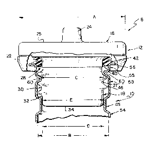
Fig. 1 is a sectional view of a vehicle fuel cap
engaging a vehicle fuel filler neck of the present
invention; and
Fig. 2 is a sectional view of a vehicle fuel cap
engaging an alternate embodiment vehicle fuel filler neck
of the present invention.
A filler cap and neck assembly 8 for a vehicle
fuel tank (not shown) is shown in Fig. 1 as including a
filler neck 10 into which vehicle fuel can be introduced
and a filler cap 12 for closing the open end of the
filler neck 10. Filler cap 12 includes a generally
disk-shaped shell portion 16 which is provided for
covering the opening in the filler neck 10 and a closure
member 18 which is insertable into the opening in the
~5 filler neck 10 for engaging the filler cap 12 to the
filler neck 10, and for sealing the opening in the filler
neck 10. The shell portion 16 includes a skirt 22 which
extends radially outward beyond the outer periphery of
the filler neck 10. The skirt 22 has a diameter A which
is greater than the diameter of the filler neck 10 to
: : ,. ... .. .
. . -: ~ ,
-: : .,:
. .
`
~5~
prevent the shell portion 16 from being inserted into the
filler neck 10. A knob 24 or other handle is formed on
the axially outwardly facing surface 25 of the shell
portion 16 for permitting a user to grasp the shell
portion 16 to rotate the cap 12 into and out of
engagement with the filler neck 10.
The closure member 18 of the cap 12 is gen~rally
cylindrical and includes a radially outwardly facing
surface 27 having an axially outer portion 28, an axially
middle portion 30, and an axially inner or pilot portion
32. The axially inner end of the axially inner portion
32 terminates at an axially inwardly facing surface 34.
The axially outer portion 28 includes a means (not shown)
for engaging the shell portion 16. One type of
engagement means is shown in Sloan, Sr. U.S. Patent No.
4,091,955. A groove 40 is provided on the axially outer
portion 28 of radially outwardly facing surface 27. The
groove 40 provides a seat for a split O-ring 42.
The axially middle portion 30 of radially
outwardly facing surface 27 includes a radially outwardly
extending spiraling thread 46, which is formed thereon.
The axially inner portion 32 of the radially outwardly
facing surface 27 is generally cylindrical and has an
outer radial diameter E.
Filler neck 10 cornprises a generally cylindrical
tube 54 having a generally constant diameter B throughout
its length, except for por-tions of the filler neck 10
which are in axial alignment with the filler cap 12 when
the filler cap 12 is engaged with the neck 10. The
filler neck 10 includes an axially outer portion 55
~ . . - . .,.. : .
' ~ : :
., ... ,' " ': ' '
7~
having a radially outwardly extending lip such as end
flange 56. The axially outer surface of end flange 56
provides a first seating point upon which O-ring 42
seats. The axially middle portion 58 includes a radially
inwardly extending spiraling thread 60 which is sized and
positioned for recei~ing the spiraling thread 46 of the
radially outer surface 27 of the axially middle portion
30 of a closure 18. The engagement between the threads,
46, 60 of the cap 12 and filler ne~k 10 comprises the
second seating point between the cap 12 and filler neck
10.
The spiraling thread 60 is preferably rolled
into the filler neck lO and has a radial diameter C
(between opposed peaks) which is sized to receive the
thread 46 of cap 12 relatively loosely. ~A relatively
loose fit between thread 46 and thread 60 is preferable
to minimize the friction between the threads 46, 60. The
friction is minimized between the threads 46, 60, to
prevent a gas station attendant or vehicle owner from
incompletely installing the cap 12 into the neck 10. A
large amount of friction between the neck 10 and cap 12
might prevent the user from fully engaging the thread 46
of the cap 12 onto the thread 60 of the neck 10. The
diameter C between opposed peaks of thread 60 should also
be large enough to enable the axially inner portion 32 of
the cap 12 to pass inwardly past the thread 60
unimpeded. Therefore, diameter C should be greater than
diameter E, the diameter of the axially inner portion of
the cap 12.
The axially inner portion 65 of the neck 10 has
'
'
' , ~ ' '
"' , ; ' ' ' ~ 1" "' ,' ~
'
'', ' ' ' ' '"'`,'' "' ' ' '
. . .
~2~
--6--
a reduced radial diameter D which is sized for receiving
the axially inner portion 32 of the radially outer suface
27 of the cap 12 in a closely spaced relation. The
diamete- D of the axially inner portion 65 is preferably
great enough to receive the axially inner portion 32
without causing any substantial friction betwe~n the
respective axially inner portions 32, 65, but to be small
enough to prevent any substantial radial movement of the
axially inner portion 32 of the cap 12 in the axially
inner portion 65 of the filler neck 10. The diameter D
of the axially inner portion 65 of filler neck 10
approximates, but is slightly greater than the diamter E
of the axially inner portion 32 of cap 12.
For example, it has been found by applicants
that the clearance between the axially inner portions 32,
65 of the cap 12 and filler neck 10, respectively, should
be between approximately . 002 inches (.051 mm) and .014
inches (.36 mm) and preferably .010 inches (.254 mm).
Thus, for example if the outer diameter E of the axially
inner portion 32 of the cap 12 is 1.555 inches (39,5 mm),
the inner diameter D of the axially inner portion 65 of
the filler neck 10 should be a maximum of 1.569 inches
(39.9 mm) and preferably 1.565 inches (39.75 mm). Care
should be taken to ensur that the clearance between the
axially inner portions 32,65 not be too large. If the
clearance between the axially inner portions is too
large, the axially inner portion 65 of the neck may not
prevent sufficiently the radial movement of the axially
inner portion 32 of cap 12.
The closely spaced relation between the axially
.
,. .:
-: , :
- . ': . : ~ ' ' ' ' ` ;
~5~7~
--7--
inner portions 32, 65 of the cap 12 and neck 10,
respectively, comprises a third seating point for the
cap. The reduced-diameter axially inner portion 65 is
preferably formed in much the same rnanner as thread 60,
that is, by rolling the reduced diameter axially inner
portion 65 into the filler neck 10.
The axially inner portions 32,65 of the cap 12
and filler neck 10, respectively are axially positioned
relative to each other 32,65 to provide at least about a
1/8" (3.175mm) axial overlap between the axially inner
portions 32,65. A cap 12 used with the filler neck 10 of
the present invention preferably includes an axially
inner portion having an axial length of .175 inches
~4.45 mm) between the axially inwardmost portion of
thread 46 and the axially inner end of the cap 12.
The three seating point arrangement of the
present invention helps to maintain a secure seal between
the cap 12 and neck 10 in the event that a radially
directed force is exerted against the shell 16 of the cap
12. When the cap 12 is properly seated in the filler
neck 10, the engagement of the O-ring 42 and lip 56
provide a fluid and vapor-tight seal for the opening of
the filler neck 10. The closely spaced relation between
the axially inner portions 32,65 of the cap 12 and neck
10, respectively, helps to prevent radially directed
forces, which are exerted against the shell 16 of the cap
12, from causing radial movement of the axially inner
portion 32 of the cap 12. In the absence of the closely
spaced relation between the axially inner portions 32,65
of the filler cap 12 and filler neck 10, these radially
.. . - . ........... . . . .
. ' ~ ,
..
'. ~:
~5(~
--8--
directed forces could cause the cap 12 to become tilted
in the neck lO. This tilting could cause one portion of
the O-ring 42 to be relatively more compressed and a
diametrically opposed portion of the ring 42 to ~ecome
relatively less compressed. If the radially directed
force exerted on the shell 16 were great enough, this
tilting could be sufficient to permit vapor or liquid to
escape past the less compressed portion of the O-ring 42
and out of the filler neck 10. By preventing radial
movement of the axially inner portion 32 of the cap 12,
the reduced-diameter portion 65 of the filler neck 10
helps to maintain a relatively constant pressure along
all points of engagement between the O-ring 42 and end
flange S6.
A second embodiment of the present invention is
shown in Fig. 2 as including a filler cap 12 which is
generally similar to filler cap 12, shown in Fig. 1.
Filler cap 12 is received in a generally cylindrical
tubular filler neck 75 which has an axially outer portion
55 and a threaded axially middle portion 58 generally
identical to the axially outer and axially middle
portions 55, 58 of filler neck 10 shown in Fig. l.
Filler neck 75, however, has an axially inner portion 78
which does not have a reduced diameter. Rather, the
diameter H of the axially inner portion 78 is generally
constant throughout the length of the tube 75, except for
the radially inwardly rolled threads 60 and the radially
outwardly disposed flange 56.
A hardened plastic annular ring 86 is inserted
into the axially inner portion 78 of the filler neck 75
'.: ., ` . . . , ` ' '.'~ ~
:~ '~ .,., ` '' : '
: , : ' ' ,: '`
, . ,,, . . , ' .
to provide a reduced diameter axially inner portion. The
annular ring 86 is provided for receiving the axially
inner pilot portion 32 of cap 12 in a closely spaced
relation to prevent radial movement of the cap 12 in the
filler neck 75. Annular ring 86 performs the same
function as reduced-diameter, axially inner portion 65 of
filler neck 10, shown in Fig. 1.
The annular ring 86 includes an annular outer
surface 90 having a diameter K which is sized to be
received snugly by, and engage the interior wall 92 of
the filler neck tube 75. A chemical or mechanical
fastening means can be provided for securing the ring 86
to the interior wall 92. The annular ring 86 also
includes an annular inner surface 94 having a diameter J
which is slightly greater than the outer diameter E of
the axially inner portion 32 of cap 12. The general
relationship between the sizes of the diameters E, J of
the cap 12 and annular ring 86, respectively, is
generally similar to the relationship between the
diameters D, E of the axially inner portion 65 of filler
neck 10, and the outer diameter of the axially inner
portion 32 of cap 12, shown in E'ig. 1.
Although the invention has been described in
detail with reference to certain preferred embodiments
and specific examples, variations and modifications exist
within the scope and spirit of the invention as described
and as defined in the following claims.
,. " ,; ,
.
,~ . , ,:,
. : . .,
-, ~ : - , . .
, ~