Note: Descriptions are shown in the official language in which they were submitted.
~6S571
REFRIGERATED SHOWCASE
The present invention relates to improvements
in a refrigerated showcase that is equipped in a super
market or the like.
BRIEF DESCRIPTION OF THE DRAWINGS:
The above-mentioned and other objects, features
and advantages of the present invention will become more
apparent upon a perusal of the following specification
taken in conjunction with the accompanying drawings,
wherein:
Fig. 1 is a perspective view, partly in longi-
tudinal cross-section, showing one example of the refrig-
erated showcases in the prior art;
Fig. 2 is a longitudinal cross-section side view
of the same;
Fig. 3 is a longitudinal cross-section side view
showing another example of the refrigerated showcases in
the prior art;
Fig. 4 is a longltudinal cross-sectlon slde
view showing the same under a defrosting state;
Fig. 5 is a perspective view, partly in longi-
tudinal cross-section, of one preferred embodiment of
the refrigerated showcase according to the present inven-
tion;
~ ~!
~ . ,
.
;
,
~26S~7~,
Fig. 6 is a longitudinal cross-section view of
the same; and
Fig. 7 is a longitudinal cross-section view
showing the same under a defrosting state.
S In a heretofore known refrigerated showcase
shown in Figs. 1 and 2, a refrigerator (3) and a fan (4)
are contained within a duct (2) for circulating a refrig-
erated air to refrigerate fresh and/or refrigerated goods
displayed in the showcase, which duct is provided in the
bottom wall (1) of the showcase, the front end of the duct
(2) communicates with an intake port (5) at the bottom
edge of a front opening of the showcase, and the rear end
of the duct (2) extends vertically in the rear wall (6)
of the showcase, further extends through the top wall (7)
of the showcase and co~municates with a blow-out port (8)
at the top edge of the front opening of the showcase.
Outside of and in parallel to the duct (2) are
provided ducts (2') and (2~) for circulating a cold air
to prevent temperature rise of the refrigerated air for
refrigerating the fresh and/or refrigerated goods dis-
played in the showcase, the front ends of the respective
ducts (2') and (2~) communicate with intake ports (S')
and (S") at the bottom edge of the front opening of the
~.....
~26S57~
showcase, the rear ends of the ducts (2') and (2") extend
through the rear wall (6) of the showcase and the top wall
(7) of the showcase and communicate with blow-out ports
(8') and (8") at the top edge of the front opening of the
showcase, and fans (9) and (10) are provided within the
respective ducts (2') and (2").
Accordingly, the refrigerated air for refrigerat-
ing the interior of the showcase, which has been sucked
into the duct (2) by the fan (4) and refrigerated by the
refrigerator (3), passes through the duct (2) provided in
the bottom wall (1), rear wall (6) and top wall (7) of
the showcase, then it is blown out of the blow-out port
(8) at the top edge of the front opening of the showcase
and sucked into the intake port (5) at the bottom edge of
the front opening, and while the refrigerated air circulates
across the front opening of the showcase and through the
rear wall (6) and top wall (7) of the showcase, it refrig-
erates the fresh and/or refrigerated goods (12) placed on
shelves (11) within the showcase and on the bottom wall (1).
On the other hand, the air ~ucked lnto the ducts
(2') and ~2") throu~h the intake ports (5') and (5") at
the bottom edge of the front opening by the fans (9) and
(10), is cooled by the refrigerator (3) and the refrig-
erated air in the duct (2) while it flows through the bottom
wall (1), rear~wall (6) and top wall (7), then it is blown
-- 3
~2655~1
out of the blow-out ports (~') and (8") at the top edge
of the front opening of the showcase, and thereby it forms
a low-temperature air curtain on the outside of the flow
of the refrigerated air for refrigerating the interior of
the showcase at the front opening of the showcase so that
the refrigerated air for refrigerating the interior of
the showcase may not come into direct contact with the
ambient air and result in temperature rise.
However, even if the invasion of the ambient
air into the showcase is prevented by the above-described
air curtain, the ambient air would mix with the air curtain
and the refrigerated air for refrigerating the interior
of the showcase as shown by arrows A, and thereby the
refrigerating effect is degraded at the lower shelves in
the showcase as compared to the higher shelves.
In order to prevent such degradation of the
refrigerating effect in the lower portion of the showcase,
as shown in Fig. 3, a somewhat improved refrigerated show-
case was proposed, in which refrigerated air blow-out
ports (13) are opened in the rear wall (6) of the showcase
to introduce the refrigerated air directly into the intarior
of the showcase. In Fig. 3, component parts which are
equivalent to those provided in the refrigerated showcase
shown in Figs. 1 and 2, are given like reference numerals.
However, in the last-mentioned improved case,
.. . .
~265571
although the refrigerating effect for the interior of the
sh~wcase is improved, upon defrosting the refrigerator
(3) the air at an elevated temperature would invade into
the interior of the showcase through the above-mentioned
blow-out ports (13) as shown by arrows B, and would come
into direct contact with the fresh and/or refrigerated
goods (12), resulting in deterioration of the quality of
the goods. In Fig. 4 which shows a defrosting state of
the same refrigerated showcase, reference numeral (14)
designates a heater in an operating state.
SUMMARY OF THE INVENTION:
It is therefore one object of the present inven-
tion to provide an improved refrigerated showcase which
is free from the above-mentioned shortcomings of the
xefrigerated showcases in the prior art.
According to one feature of the present inven-
tion, there is provided a refrigerated showcase of the
type that a refrigerated air for refrigerating the interior
of the showcase and preventing an ambient air from invading
into the showcase is circulated across a front opening of
the showcase and through a bottom wall, a rear wall and
a top wall of the showcase, in which a gas-pérmeable spacer
is disposed at the rear of shelves within the showcase as
spaced from the front surface of the rear wall to form
,
~26557~
a refrigerated air introducing duct space between the
spacer and the rear wall.
According to the present invention, since the
refrigerated showcase is constructed in the above-featured
manner, a part of the refrigerated air for refrigerating
the interior of the showcase that is blown out of the blow-
out port at the top edge of the front opening of the show-
case advances into the refrigerated air introducing duct
space formed between the gas-permeable spacer and the rear
wall and flows downwards. At this moment, the refrigerated
air flowing down through the duct space would permeate
through the gas-permeable spacer and would flow onto the
upper surfaces of the respective shelves, and thereby the
goods displayed on the respective shelves are wrapped up
in the refrigerated air. Moreover, in association with
the fact that the refrigerated air flowing down through
the above-mentioned duct space would not mix with the
ambient air and hence would not be subjected to temper-
ature rise, the goods displayed on the respective shelves,
especially, the goods displayed in the lower portion of
the showcase can be refrigerated effectively.
In addition, according to the present invention,
upon defrosting the air heated up to a raised temperature
flows through the duct in the showcase and is prevented
from invading into the interior of the showcase, and hence
-- 6
i _i,
~2~55~1
the heated air would not come into direct contact with the
goods on the shelves and would not deteriorate the quality
of the goods.
In summary, in the refrigerated showcase accord-
ing to the present invention, owing to the fact that air-
permeable spacer is disposed at the rear of the shelves
within the showcase as spaced from the front surface of
thè rear wall, the refrigerating effect for the goods
within the showcase can be enhanced, and deterioration of
the quality of the goods within the showcase upon defrost-
ing can be prevented.
DESCRIPTION OF THE PREFERRED EMBODIMENT:
Now one preferred embodiment of the present
invention will be described with reference to Figs. 5 to
7, wherein component parts which are equivalent to those
lS of the refrigerated showcase in the prior art as illustrat-
ed in Figs. 1 to 4 are given like reference numerals.
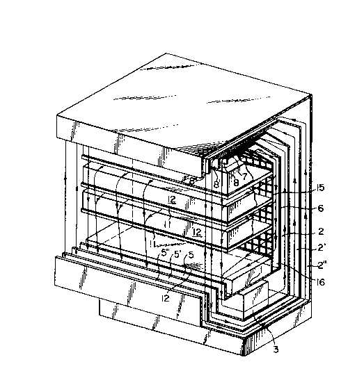
As shown in Figs. 5 and 7, a gas-permeable spacer
(15) is disposed vertically at the rear of the shelves in
the showcase as spaced from the front surface of a rear
wall (6) of the showcase, and thereby a refrigerated air
introducing duct space (16) if formed between the spacer
(lS) and the rear wall (6).
While the gas-permeable spacer ~15) is formed
of a network body in which metal rods or synthetlc resin
-- 7
, ~ ~
`;
`
:
~26~S71
rods are arrayed in a lattice form in the illustrated
embodiment, it could be formed of a perforated plate or
a fibrous fabric.
Since the illustrated embodiment is constructed
as described above, a refrigerated air for refrigerating
the interior of the showcase, which was sucked into a
duct (2) provided in a bottom wall (1), a rear wall (6)
and a top wall (7) of the showcase by a fan (4), is blown
out of a blow-out port (8) at the top edge of a front
opening of the showcase, a part of the refrigerated air
flows straightly towards an intake port (5) at the bottom
edge of the front opening of the showcase to form an air
curtain as shown by arrows X in Flg. 6, but another part
of the refrigerated air flows along the top surface of the
uppermost shelf (11) or goods (12) on the same shelf (11),
then advances into a refrigerated air introducing duct
space (16) formed between the gas-permeable spacer (15)
and the rear wall (6) and flows down through the same
space (16) up to the lowermost portion, as shown by
arrows Y.
While the refrigerated air for coo:l.lng tho
interior of the showcasc flows down through khe above-
mentioned space (16), a part of the refrigerated air
penetrates through the gas-permeable spacer (15) and then
flows along the top surfaces of the respective shelves
126~571
(11) or goods (12) on the respective shelves~ as shown by
arrows Y'.
Accordingly, the goods on the respective shelves
(11) would have their outer peripheral surfaces wrapped
S up ln the refrigerated air for refrigerating the interior
of the showcase, and in association with the fact that
the refrigerated air flowing down through the space (16)
would be almost not subjected to temperature rise because
it does not mix with the ambient air, the goods on the
respective shelves (11) in the showcase, especially the
goods on the lowermost shelf (11) can be refrigerated
effectively.
It is to be noted that although the front faces
of the shelves are positioned generally at the rear of
the plane directly connecting the blow-out port and the
intake port of the refrigerated air for refrigerating
the interior of the showcase so that the air curtain
formed of the refrigerated air may not be broken by the
shelves, in the illustrated ernbodiment, the depth oE the
blow-out port (8) of the refrigerated air is made larger
to make the thickness of the air curtain thLc)cer so that
the rear portion of the same air curtai.n may collide with
the shelves, and thereby the refrigerated air for refrig-
erating the interior of the showcase can be introduced
more smoothly into the refrigerated air introducing duct
' ` :
. . .
~26SS~
space (16) at the rear within the showcase without break-
ing the air curtain across the front opening of the
refrigerated showcase.
Upon defrosting, the front opening of the goods
displaying space within the showcase is covered by a cover
(17) after closure of the super market where the refrig-
erated showcase is equipped, then air at a raised temper-
ature is introduced into the respective ducts (2), (2')
and (2") and is circulated therethrough. At this time,
the air at the raised temperature would not come into
direct contact with the goods (12) on the shelves (11),
and therefore, the quality of the goods (12) would not be
deteriorated.
Since many changes could be made in the above
construction and many apparently widely different of this
invention could be made without departing the scope
thereof, it is intended that all matter contained in the
above description or shown in the accompanying drawings
shall be interpreted as illustrative and not as limiting.
- 10 -