Note: Descriptions are shown in the official language in which they were submitted.
~2655~34
1 This invention relates to a device, system and a
method for determining the direction of a source or a sink
of an electrical signal in a medium permitting the signal
to pass.
In the past, it has been possible to determine the
existance of an electrical signal. However, the determin-
ation of the direction of the source of the s~gnal has been
difficult, particularly when the strength of the signal is
low.
Accordingly, in one of its broad aspects, the
invention resides in providing an electronic detecting
device for determining the direction of a source or a sink of
an electric~l signal, in a medium permitting the signal to
pass, comprising: at least one set of at least two spatially-
separated receiving means capable of receiving the
electrical signal; a comparing means Eor comparing the
strength of the electrical signal received at a first re-
eeiving means of said at least one set of reeeiving means
to the strength of the electrical signal received at a
selected other recei.vlng means of sa.id at least one set, for
eaeh set; and an .inclicatin~3 means ~or .incl;i.catlng when the
strength oE the signal recei.va(l at the :i.rst rec~iving means
of said at least one set becomes either greater than or lesser
than the strength of the signal received at the other sel-
eeted reee.iving means of said at least one set, for eaehset.
In another of its broad aspects, the invention
5584
1 resi.des in providing an electronic detecting device for
determining the direction of a source or a sink of an elec-
trical signal, in a medium permitting the signal to pass,
comprising: at least three spatially-separated receiving
S means wherein each receiving means is capable of receiving
the electrical signal, and the first and second receiving
means have an electrical connection therebetween comprising
a resistance means; a comparing means for comparing the
strength of the electrical signal received at the third
receiving means to the strength of the electrical signal
occurring at a selected postion on the electrical connection;
and an indicating means for indicat;ng when the strength
of the signal received at the third receiving means becomes
either greater than or lesser than the strength of the sig-
nal occurring at the selected position on the electricalconnection.
In yet another of its broad aspects, the invention
resides in providing a system for detecting the d.irection
of a source or a sink of an electr.ical signal in a medium
permitting the signal to pass, comprising: a generator for
generating the signal; at least one source from which the
signal can emanate and which is connected electrically to
the generator; a sink which is conn~cted el~ctrically to
the generator, but not s~ormally connected e:lectrically
to the source; and a detecting device as de:Eined above.
In still another of its broad aspects, the inven-
tion resides in providing a method of determining the
~2655B~
1 direction of a source or a sink of an electrical signal in
a medium permitting the signal to pass, comprising: using
at least one set of at least two spatially separated probes;
detecting, for each set of probes, the signal at a first
probe and at a second probe, for at least two spatial
orientations of said at least one set of probes; comparing,
for each set of probes, the strength of the signal detected
at the first probe to the strength of the signal detected
at the second probe, for each spatial orientation and
determining, for each set of probes, for which spatial
orientation the strength of the signal detected at the
first probe becomes either greater than or lesser than the
strength of the signal detected at the second pro~e.
In another of its broad aspects, the invention
resides in prov.iding a method of determining the direction
of a source or a sink of an electrical signal in a medium
permitting the signal to pass, comprising: detecting the sig-
nal at a first location; detectlng the signal at each of at
least two posltions on a resistance means ~hich electrically
connects a second location and a third location; comparing
the strength of the s:ignal detected at the :E.irst locat.ion
to the strenyth o.E thc.! sicJnal. dote~totl at ~Gh o~ sa.Ld at
least two pQq.it.ions on khe .r~istor means; ~nd det~.rm:Lning
for which position the streng-th oE the signal detected at
the first location becomes either greater than or lesser than
the strength o:E the signa:L detected at positions on the
resistor means.
--3--
,
.: .
~26S~i~4
1 Further aspects of the invention will become
apparent from the following descriptionsof the invention
and the preferred embodiments thereof.
In the drawings, which illustrate the invention
and embodiments thereof:
Fig. 1 shows a system of the invention;
Fig. 2 shows some geometrical principles of the
invention;
Fig. 3 shows a preferred signal of the invention;
Fig. 4 shows another preferred signal of the
invention;
Fig. 5 shows a circuit diagram of a transmitter;
Fig. 6 shows a circuit dia~ram of part of the
detecting device of the invention;
Fig. 7 shows a circuit diagram of part of the
detecting device of the invention;
Fig. 8 shows an application of the invention
respecting a reservoir;
Fig. 9 is an explanatory diagram for an embodi-
ment of the invention;
Fig. 10 shows an application of the inventlonrespecting a pipe;
Fig. 11. show~ a ~u.rth~r ~mbodlment oE th~ invention;
and
Fig. 12 shows a further embodiment of the inventiOn.
~2~iS5~4
1 This inven-tion relates to a method for determining
the direc-tion of the source or a sink of a suitable elec-
trical signal in a medium which permits the signal to pass
therethrough, and a device and a system therefor.
Fig. 1 shows an embodiment of the system of the
invention. The embodiment includes a generator 10, a source
12 and a sink 14. The generator 10 is any generating means
which is capable of generating a suitable signal. The
generator 10 is connected electrically to a source 12~
The source 12 is any suitable means from of which the
signal can be emanated or transmitted through the medium
16 from the source 12 to the sink 14.
The sink 14 is any suitable means which can receive
the electrica] signal after it has been emanated from the
source 12 and after it has passed through the medium 16.
The sink 14 is connected electrically to the generator 10,
but it is not normally connected electrically to the source
12. The electrical connection between the source 12 and the
sink 14 is obtai.ned through the medium 16. Thus, if the
medium 16 is one which permits a suitable signal to pass
--5--
' :r,
~265~
1 therethrough, a suitable signal generated from the signal
generator 10 will pass through the medium 16 from source 12
to sink 14. However, if the medium 16 is one that does not
permit the signal to pass, there will be no electrical con-
nection between the source 12 and the sink 14, and the sig-
nal will not pass therebetween. Accordingly, if the medium
16 is one which permits a suitable signal to pass there-
through, the electrical circuit From the generator 10, to
the source 12, to the sink 14 and to the generator 10 will
1~ be completed between the source 12 and the sink 14 by the
path which the signal takes from the source 12 to the sink
14 through the medium 16.
It has been discovered that the signal usually
takes more than one path through the medium 16 from the
source 12 to the sink 14. It is believed that each of these
several paths has the same total resistance from source 12
to sink ].4. Two paths of the signal in medium 16 are shown
in Fig. 1 as 18 and 20.
--6--
~655~
1 It will be understood that, in one sense, the
source 12 is different than the sink 14, in that the signal
emanates from the former and is received by the latter.
However, the source 12 and the sink 14 can be considered
to be equivalent if only the presence of a path.which the
signal takes between the source 12 and sink 14 is consid-
ered. Thus, the invention is capable of detecting either
the source 12 or the sink 14. Accordingly, when the term
"source" is referred to in the sense of detecting the di-
rection of a source, it will be understood that "source"can mean either a source or a sink.
It has ~een discovered that the directors of the
source 12 or the sink 14 of the signal can be determined if at
least two points are found in the medium 16 for which the
strengthsof the signa~ at those points are the same and if
those points are equidistant from either the sink 14,or
from the source 12. It has been found that the direction
of the source 12 or the sink 14 lies in the direction of
. the bisector of the line which joins the two points where
the strengths of the signalsare equal.
Although the precise reason for th:i~ phenomenon
i9 not completely und~r:toocl, lt :I.s bel.ieved that th@
strength Oe the ~ignal clet.ected at any given point on a
path of the signal through the medium 18 depends on the
ratio of the electrical resistance of the medium 18 between
the source 12 and the point to the electrical resistance
of the medium 18 between the point and the sink 14. Thîs
, . ,,~ . . .
~655~
1 ratio will be referred to as the resistance ratio.
It is further believed that the resistance oE a
medium over ~ given path is primarily dependent upon the
electrical resistivity of the medium and the length of the
path through the medium. ThUs, if the resistivity of the
medium is uniform or approximately uniform throughout the
medium, the resistance ratio reduces to a distance ratio.
The distance ratio is the length of the path from the source
to the point to the length of the path from the point to
the sink.
Thus, i~ the strength of the signal at a point
on the path, say point A on path 18, is equal to the strength
of the signal at a different point on a d:ifferent path,
say point B on path 20, the respective distance ratios re-
spectiny those points should be equal. Now, if it is knownthat the lengths of the paths from the source 12 to the
respective points are equal, the lengths of the paths from
the sink to the respective points must also be equal.
Similarly, if the lengths of the paths from the sink 14 to
the respective points are equal, the lengths of the paths
from the source 12 to the respectlve point5 must also be
equal.
Thus, Eor the cases ~g described above, ~y the
geometrical ~elationships as shown in Fig. 2, it is deter-
mined that the direction of the source 12 or the sink 14lies in the direction of the bisector of the line that joins
the points A and B.
~26~5~4
1 IE the leng~hs of the paths from the respective
points of equal signal strength to either the source 12 or
the sink 14 are not e~actly equal, it has been found that
the bisector of the line joining the points indicates
approximately the direction of the source 12 or the sink 14
A unique detection device to be used in determin-
ing the direction of a source or a sink of an electrical
signal in the medium allowing the signal to pass is provided.
In its most basic form, the device comprises three elements:
a receiving means; a comparing means; and an indicating
means.
The receiving means comprises at least two separate
means for receiving or detecting the electrical signal in
the medium. Preferably, the receiving means are electrical
probes.
The probes can be of any form which is suitable
for the particular application, for example, long, slender
rods for penetrating the earth.
The probes need not be fixed in any spatial relation
ship but they can be fixed in a spatial relationship to
each other, such as on a frame. It will be understood that
to obtain suitable result~, the probes æhollld b~ ~s~d t~
detect the signal at po:int~ hav~ng a spatial æepar~tion.
The comparing means is any means which can be used
for cornparing the strength of the electrical signal received
at the first probe to the strength of the signal received
at the second probe. Ideally, ït is desired to determine
~2~ 4
l when the strengths of the signals rece~ved ~t the two probes
are equal. Ideally, this can be accomplished by using a
"null" circuit. However, it has been discovered that it is
quite difficult ~n practice to implement a "null" circuit
which accurately determines the "null" point. Accordingly,
the invention prov~des for the use of a "cross-over" circuit.
That is, rather than determining when the strengths of the
detected signal are equal, it is determined when the differ-
ence between the signals detected at the two probes changes
from positive to negative, or vice versa. In other words,
this embodiment of the invention determines when the strength
of the signal received at one probe becomes greater than
or lesser than the strength of the signal received at the
other probe.
It is possible to make such a determination as
discussed above in some instances when the signal is a
direct current signal. However, it has been found that as
the strength of the direct current signal become low, it
becomes very difficult to accurately determine the strength
of the signal. It is believed that this is due to the
direct current, galvanic potentials developed due to the
dissimilarit:ies between thc probe ancl the surround.ing m~dlum.
In ord~r to overcom~ thi~ problem, it has been
discovered that if the signal has a pulsed, asymmetric
~5 waveform, su.itable electronic circuitry can be built which
perm:its detection of the signal at signal strengths much
lower than acceptable signal streng-ths for direct current
--10--
~26S5~3~
1 siynals. For presen L purposes, a signal having a pulsed,
asymmetric waveform is one that has a non-zero average value
over one period.
One preferred waveform is a pulsed, asymmetric,
rectangular waveform. A representat~ve example of this
type of waveform is shown in Fig. 3.
lt is possible to use signals having a pulsed,
symmetric waveform, but the electronic circuitry necessary
to successfully compare the strengths of the signals at the
different probes, requires synchronization. This increases
the complexity and cost of the circuitry.
It has been found that it is relatively easy to
amplify and limit as many times as is required to practically
obtain a suitable si~nal when the signal has a rectangular, pulsed,
asymmetric waveform. When such a signal has been detected
and suitably amplified, the average value of the detected
signal can be determined. The average value of the signal
is a non-zero value because the signal has a pulsed,
asymmetric waveform.
Accordingly, the non-zero average value of the
signals detected at the two probes can compared as discussed
above to determine when the ~trerlgth o the ~:lgn~l detQctecl
at one probe becom~s eith~r cJrC~ater than or lesser t.han the
strengths of the signal detected at the other probe~
It has been found that signals having a pulsed,
asymmetric, rectangular waveform are suitable when the
frequency of the signal is considerably greater than 300 Hertz.
~55~ -
I However, when the frequency of tne signal is around 300 Hertz,
it has been found that better performance can be obtained
when the signal has a ramp-like pulsed, asymmetrlc wave-
form such as is shown in Fig. 4.
If a signal having a ramp-like, pulsed, asymmetric
wavefore is used, the probes detect th~s type of signal but
the signal is passed through a transforming means before
the strengths of the signals are compared. The transforming
means transforms the signal having a ramp-like, pulsedl
asymmetric waveform into a s;.gnal having a rectangular,
pulsed, asymmetric waveform. The transformed signal can
thus be suitably and easily ampl.ified and limited. The
transforming means can be a transformer.
The device of the invention ;ncludes some indicat-
ing means which indicates when the strength of the signal
received at one probe becomes either greater than or lesser
than the s.trength of the signal received at the other probe.
It ;s possible to have any sort of indicating means such as
a ligh.t or a d:~al. However, a preferred indicat;ng means
will produce an aural stimulus. The aural stimulus could
be an audible beeping or buzzing sound. It will be apparent
to a person skillcd in the art how to provide snd p:roduce
a suita~le indicatinc3 m~an~.
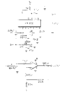
Preferred electrical circuits respectinc~ certain
aspects of the above-described device are shown in Figs. 5,
6 and 7. Fig. 5 S}lOWS a combined yenerator and source;
Fig. 6 shows a portion of a preferred detecting circuit; and
~.2~5~
. 7 shows further portions of a preferred detecting
circuit.
With respect to these circuits, it is very import-
ant to ensure -that the transmitting and generating circuits
are electrically separated fromand isolated from the
de-tecting and comparing circuits. Otherwise, spurious
signals will interfere with accurate comparisons.
During operation, the detecting device of this
invention is used as follows, with reference to Fig. 1.
A signal generator 10 is used to generate a suitable elec-
trical signal as discussed above. The generator 10 is
connected electrically to at least one transmitter or scurce
12. The yenerator 10 is also electrically connected to a
sink 14. The source 12 and the sink 14 are r.ot normally
electrica].ly connected.
The source and the sink 14 are positioned in the
medium 16. A suitable signal is generated in the generator
10 and it is transmitted from the source 12. If the medium
16 is such as to permit .the signal to pass, the signal will
pass to the sink 14 via several paths in the medium 16.
At least one set of probes A, B of the detecting
device is placed into the mecl:ium 16, ellch p~be ~ e.iny
placcd at ~patially-~Qparatod locatl~rl~ in th~ m~dium 16.
-13-
~2~SSi~3~
1 The signal is detected by each probe at its
respective location. The strengths of the signals detected
at the respective locations are compared. The at least
one set of probes A, B is then moved to a different spatial
orientation so that the location of at least one probe of
the set of probes is different. Next, the signal is detected
at the locations of the new spatial ori~entation and the
strengths of the signals at those locations are compared.
If there is no indication that the strength of the signal
detected a probe A has become greater than or lesser than the
strength of the signal detected at probe B, the probes of
each set of probes are then moved to further different
spatial orientations until the strength of the signal
detected by one probe is indicated to have become greater
or lesser than the strength of the signal detected by the
other probe. When this indication is made, the operator
knows that the direction of the sink 14 lies along the
direction of the bisector of the line joining the two probes
when the indication was made.
It will be understood that the detecting device
is not limited to only one set of probe~ and that each set
of probes is not limited to onl~ two prob~s. :~n d:iEE~renk
situations, a different number oE sets of probes and a
different number of probes comprising each set could be
used.
One application of the invention is in finding
the location of a "leak" in certain materials. With reference
~265~i~4
1 to Fig. 8, there are ~any situation~ where a ~eservior 22
for containing a fluid 24 or other suitable material develops
a leak or opening 26 in the fluid-impervious barrier 28
of reservior 22. If the reservior 22 is surrounded by
another material 30, such as when -the reservior 22 is com-
pletely or partially underground and therefore surrounded
by earth., it is difficult to detect the location of the
opening 26 where the fluid 24 is escaping. If the barrier
28 is a material that does not normally permit a signal
suitable for this invention to pass therethrough and the
fluid 24 or other suitable material is one that does normally
permit a signal suitable for-this invention to pass there-
through,the location of the opening 26 can be located as
described below. If the surrounding material 30 is one that
does not normally permit a signal suitable for this invention
to pass therethrough, it is necessary for the fluid 24
which has escaped from the reservior 22 to spread out from
the opening 26 to form an electrical path between the
sink 14 and the opening 26.
A source such as a transmitter 32 is placed inside
the reservior 22 and is electrically connected to a gener-
ator 34 which is capable oE generating a signa:L suikable
for th.is inventi.on. The ~nexatoe 34 i.~ al.~o electric~.L:Ly
connected to a ~in]c such a~ a geound rod 36 which is placed
outside of the reservior 22.
If there is no leak. or opening 26 in the barrier
28, there will be no electrical path.along which the signal
-15-
.. . .
. .
- '
~:6~
1 can travel from the transmitter 32 to the ground rod 34
because the barrier 2~ does not permit the signal to pass
therethrough. However, if there is an opening 26 in the barrier
28, the signal will pass through the barrier 28 at opening
26,and if the surrounding material 30 is such as to permi-t
the signal to pass, the electrical loop can be connected
between the opening 26 and the ground rod 36. However, if
the surrounding material 30 is such that it will not permit
a suita~le signal to pass therethrough, the electrical loop
between the opening 26 and the ground rod 36 will be com~
pleted only when the fluid 24 or other suitable material
contained by the reservior 22 has diffused from the opening
26 to the yround rod 36.
In any case, because the signal will pass only
through the opening 26, the opening 26 acts as a local sink
for the signal. Therefore, if the detecting device of the
invention is p:Laced in the reservior 22 between the trans-
mitter 32 and ~he opening 26, it is possible to determine
the location of the opening 26 if the device is used as
explained above. Each time the indicating means of the
detecting device indicates that t:he hisector o~ the Jine
joining the two prob~s i~ in ali~nment with the openLng 26,
the operator knows in what direction he should advance in
order to locate the opening 26 ~xactly.
The invention is particularly suitable for find-
ing leaks in swimming pools. It has been found that the
invention is more useful when the sides of the swimming pool
~16-
1 are made of some sort of plastic rather than porous concrete
blocks. However, even when the sides of the swimming pool
are porous concrete blocks, the invention is useful for detect-
ing larger holes.
In further embodiments of the ~nvention tnat are useful
in locating leak in a reservi.or, the probes may be permanently
spaced apart so as to have fixed spacing. A suitable spac-
ing has been found to be about 8 inches.
In another embodimen-t, there are two i.ndependent
sets of probes with two probes in each set. Once again,
the probes of each set may be permanently spaced apart.
Also, a separate aural or visual stimulus can be used to
indicate alignment respecting each set of probes, such as
a different tones of buzzes or beeps.
Also, the two sets of probes may be aligned sub-
stantially ort:hangonally with respect to each other. For
instance, there could be an up/down pair of probes and a
right/left pair of probes. Accordingly, one pair of probes
would determine the direction of the source in the up/down
plane and the other pair of probes would determine the
direction of the source in the right/left plane.
I:E the probcs are spaced apark, i.k .is convon:ient
to posit:ion -the probes orl ~ ;Erame which i.s re.ld:i:Ly moved
by the ope:rator.
In a further embodiment of the invention~ a trans-
mitter which acts as a source of the signal is fixed perm-
anently .in spatial relationship with each probe. Thus~ for
-17-
.
~6S~4
1 example~ the transmitter could be mounted at the rearward
portion of the same frame as that on which the probes are
positioned. It is preferable to have each probe equidistant
from the transmitter.
In a further embodiment, it is possible to have
an effective source which comprises more than one actual
source. For example, there could be four actual sources
or transmitters. In this embodiment, each transmitter ls
mounted on the rearward portion of the frame such that the
distance between one transmitter and an associated probe is
the same as the distance between each other transmitter and
its associated probe.
In a further embodiment, the effective source may
comprise two actual sourees which are electrically connected
through a resistance means which is similar to the resistance
means as discussed below with respect to probes.
In a further embodiment, a front/back detector
may be included with the detecting device. Once it is
determined that the source or sink lies along the bisector
of the line joining two probes, it is not necessarily known
for sure whether the souree or sink is actually in one
direction or the other. Aecord~ncJly, with referenGe tO
~ig. 9~in orcl~r to overeome thi~ problemrtwo addltional probes C,
Dare provided whieh, prefera~ly, straddle the source 38 and
which form a straight line therewith. Also, the probes
C, D are approximately equidistant from the source 38.
It has been ~ound that the probe that li~ea in
-18-
~55~
1 between the source 38 and the sink 40 receives -the stronger
signal. Therefore, if it is desired to have a probe,
say probe D, always between the source 38 and the sink 40,
the strength of the signal at probe D can be compared to the
strength of the signal at probe C. As long as the strength
of the signal at probe D is greater than the strength of the
signal at probe C, the probe D is between the source 38 and
sink 40 and the probes are aligned as des~red.
It has been found convenient to monitor, either
continuously or periodically, the difference signal of the
signal detected at a front probe minus the signal detected
at a rear probe. So long as this difference signal is always
positive, a HI signal is produced which is used to activate
other parts of the system. If the differ~nce signal goes
negative, a LO signal is produced and the other parts of
the system will not work. Alternatively, a visual or aural
stimulus could be used such as a light or beep to .indicate
a positive difference slgnal.
A further application of the invention is in
locating holes in a pipe. Essentially, a pipe is a very
elongated reservior ancl 50 the same principle~ as d.iscussed
above will apply :in the ca~e o E a p~ipe. 'rhLs appLication
is illustratec~ .in Flg. 10 wh~re 42 is a pipe7 44 is a hole
in the pipe; 46 is a fluid or other su:itable material as
disaussed above; 48 is a surrounding medium; 50 is a source
or transmitter; 52 is a sink or ground rod; 53 is a g~ner-
ator;and A,B are probes. Fig. 7 illustrates a cross-sectional
view of the pipe 42.
S5~3~
1 Another embodiment of the invention is useful
when the probes of the detecting device are to be used for
an extended period of time in one location. Such a situation
could arise when itis desired to monitor overtime for leaks
in fluid storage reserviors which are permanently fixed.
In th~s embodiment, as shown in Fig. 11, a plur-
ality of probes A, B, C, D, E and F are placed in position
in the relevant medium 54 such that each probe is at an
equal distance,or at least an approximately equal distance,
from the source or transmitter 56. Thus, the probes are
positioned in a fan-shaped array along an arc or a circle
of constant radius r from the transmitter. The number ofprobes
and the spacing between the probes depends on the desired
sensitivity. A suitable radius separating the probes from
the transmitter 56 has been found to be about 10 feet. A
suitable separation of probes along the arc or circle is
about 3 feet between two probes.
The direction or directions in which this embodi-
ment is useful depends on whether the probes are spaced all
around the transmitter for 360 or just for a small angle
such as about 90 as shown in Fig. 11.
During use, the operator caA ~elect a first probe
as a reference probe or khe re~erence probe can be pre-
determined. The operator than samples ak a succession of
probes to find for which combination of probes there is a
"cross-over" where the strenyth of the signal detected at
the reference probe becomes either greater than or lesser
-20-
~655~
l than the signal detected at another probe. For example,
with reference to Fig. ll, probe A could be selected as the
reference probe and then the strengths of the signal detected at
probes B, C, D are compared against the strength of the
signal at probe A. If, for example, the "cross-over" occurs
at probe D, the operator knows that the sink 58 lies in the
direction of the bisector of the line AD.
It is possible to use an embodiment where the
probes are not equidistant from the transmitter 56 but in
such an embodiment the accuracy is not as good as when the
probes are equidistant from the transmitter 56.
A further embodiment of the invention comprises
replacing at least some of the plurality of probes, as shown
in Fig. 12, by two probes that are electrically connected
by some sort oE resistance means. The resistance means
effectively acts as an approximation of the medium 54 between
the two probes.
Thus, with reference to Fig. ll, probe C and
probe F are electrically connected together through a
resistance means RM. If the resistivity of the medium 54
between probes C and F is approxlmately uniEorm throughout,
the strength O:e the Si.cJnal that would have beerl det@ctacl
at probe D can be approx.imately deterlnlrled by detecting the
signal at an appropriate pos:ition on the resistance means
RM. If the resistivity of the resistance means RM is uni-
form throughout, the resistance means ~ should be sampled
at a position along the resistance means RM which has a
-21-
.
~2655~a~
1 resistance which is proportional to the entire resistance
of the resistance means RM as is the arc CD to the entire
arc CF.
Any suitable resistance means can be used including
a resistor or a potentiometer.
Thus, it can be seen that the strength of the
signal can be at least approximately determined for any
point along the arc CF and not just at the points D and E.
Therefore, a greater accuracy can be obtained in determining
where the "cross-over" occurs. Therefore, the direction of
the sink can be determined to a greater degree of accuracy.
Although it is preferred to have the resistance
means approximate the points on an arc or circle of constant
radius, the invention will work to varying degrees of
lS success even when the resistance means approximates points
other than those along an arc or circle of constant radius.
Many variations of the actual configurations and
arays of probes in combination with resistance means could
be developed, but all such configurations andarrays would
fall within the scope of the invent;on. For instance, with
reference to ~ig. 12, the probe C n~ed ~ot bo di~tal ~om th~
probe B. It is possible to have the probe C proximate t:o
probe B. Alternatively, probes C and F could straddle
another probe such as probe B. ~oreover, there could be
many probes, such as probes A and G.
-22-
~26S5i34
1 In another embodiment, there could be a pluralit.y
of sources or sinks from which any particular one could be
selec-ted at any given time to reference the system.
Although the disclosure describes and illustrates
many embodiments of the inventionr it is to be understood
that the invention is not restricted to these particular
embodiments, but that it extends to include variations
which are within the skill of the skilled reader.
-23-