Note: Descriptions are shown in the official language in which they were submitted.
~660~
The invention relates to a set up pi0ce for mounting on
a can, containing a beverage. In the lid of such a can a
substantially triangular opening can be made by tearing a part of
the lid away by means of a riveted ring and an impressed rill.
The relevant cans are marketed at a large scale for the
sales of various types of liquids, such as ~eer, lemonades,
spring en mineral water, fruit juices and the like.
The opening which can be made in the can has a slender
triangular shape, the basis of which runs along the rim of the
lid whereas the top is positioned at about the centre of the lid.
Such cans, generally, are not daily domestically used
but are, for example, used on the road in vehicles and at
locations where many people are gathering, such as sport events
and the like. In general no drinking glasses will then be
available, thus forcing the consumer to drink directly from the
can. This is not very convenient in particular for younger
children. Moreover the taste of the liquid is not brought out in
~ this way as the flavour is not smelled.
The present invention provides a set up piece
comprising a substantially cylindrical body portion which near
its lower rim is provided with clamping means for obtaining a
liquid tight connection between the set up piece and said can,
said body portion having a su~stantially radially inwardly
extending part which can engage the upper rim of a can.
According to a preferred embodiment of the set up piece
according to the invention the inwardly extending part
-- 1 --
:` f
.,, ~, .
-- 2
oE the bo~y portlon is Eorminy a bottom which is provided
with an opening corresponding with the one which can be
made in the l:id of!the can.
In this way it is possible to close the opening of the
can by rotating the set up piece in respect of -the can.
It will be obvious, -that in many cases the content of
-the can is not consumed in one time but wi-th intervals.
If in such an in-terval the can would be overturned a
part of the content should ge-t los-t and the environment
in which -the liquid is consumed might be defiled.
By means of the set up piece according to the present
invention this can be prevented.
According to an embodiment of the se-t up piece according
to the invention the clamping means for obtaining a
liquid tight connection between the se-t up piece and
-the can may have the shape of a skir-t substantially
ex-tending from the joint between the cylindrical body
portion and the radially inwardly extending part.
In particular the s]cirt may extend over a given portion
of the cylindrical wall of the can, the lower edge of
the skirt bein~ provided with an inwardly extending rib
engag:Lng said cylindrical wall of the can.
By this an excellent seal between -this wall of the can
and the set up piece can be obtained while never-theless
the set up piece can easily be moun-ted on the can.
In case the set up piece is provided with a bottom the
rotation oE -the se-t up piece in respect of the can e.g.
when closing the opening in the lid oE the can, is not
hampered by -the inwardly ex-tending rib engaging said
cylindrical wall of -the can.
The embodiment clescribed above is preferred in view of
the Eact that mos-t -types of cans con-taining a beverage
are having -the same outside diame-ter. The cans, however,
thus show several shapes of the upper part of the cylin-
~ 0%;~
drical wall where this is jolning the lid and of theconnection between said wall and said lid.
For some types of cans use can be made of a clamping
means in the shape of a skir-t substantially extending
from the joint be-tween -the cylindrical body portion and
the bot-tom and of a raised bottom portion positioned
opposite said skirt, said skirt and raised bot-tom portion
cooperating with an upstanding rim portion of the lid
of the can by which said lid is connected to the
cylindrical wall of said can.
In view of the fact that the upper surface of the lid
of a can is not entirely flat the lower surface of the
bottom of the set up piece can not lie against the lid
over its entire surface. By this the danger exists that
liquid will pass along the lower surface of the bottom
of the set up piece to the opening in the bottom also ~7hen
this opening is not in line with the one in the lid of
the can, so when the already opened can should have to
be closed off by the set up piece.
To prevent this according to the invention the lower surface
of the bottom of the set up piece is provided with a
protruding portion extending substantially along the
edge of the bottom opening.
According to a preferred embodiment said protruding portion
can be obtained by -the fact that the bottom of the set up
piece is s0mewhat slanting towards the edge of the bottom
opening over a small distance near saicl opening.
Fur-ther it is preferred that the edge of the bottom
opening near -that portion where this is nearest to the
cylindrical wall, is providecl with a raised portion.
It has appeared tha-t by this it is prevented that the
last droplets, which will be present on the bottom near
-the cylindrical wall are sucked between the bottom of
-the set up piece and the lid of the can.
~26~
Further it has appeared to be favourable when the end of
the openi.ng in -the bottom of the set up piece lying near
the cen-tre of this is formed by a straight line perpen-
dicular to the radius .Eorming -the cen-tre line of the
opening.
It has appeared that when the shape of -the opening at the
indicated place is more rounded off droplets will easier
be sucked into the space between the bottom of the set up
piece and the lid of the can.
According to a further elaboration of the invention the
bot-tom of the set up piece can be provided with a raised
centre poxtion by which it is prevented that the bottom
contacts a part of the means by which the opening in the
lid of the can is originally closed and which part,
eventually, is not totally removed when opening the can.
Further the bottom oE the set up piece can be provided
with a raised annular portion extending along the cylin-
drical body portion to prevent that the bottom of-the
can contacts an upstanding rim of a given type of can
be:Eore the bottom contacts the lid of the can in the
desired way.
According to the present invention the body portion of the
set up piece can be substantially dimensioned such that
it partly fits upsidedown over the can and as such does
not take much space in the packaging of a number of cans.
Al-ternatively the set up piece can be dimensioned such
that a number of se-t up piece~ may be slit into each other,
so that a number of set up pieces occupy the same volume
as one can.
As already indicated above a set up piece, provided with
a bottom, can be rotated around its longitudinally axis
with respect to the can, after being clamped on said can.
In this way the opening in the bottom of -the set up piece
is turned in respect of the opening in the lid of the
~L266022
can to close said opening after the related portion of the lid of
the can has been removed.
In a par~icularly preferred aspec-t thereof the present
invention provides a beverage can drinking attachment comprising
(a) a substantially cylindrical body having clamping means for
obtaining a liquid tight connection between the beverage can
attachment and a can top positioned at a lower end of said body;
(b) a disk extending substantially transverse across said body
dividing said body into a drinking portion and clamping portion,
said disk having means for engaging an upper rim of the can top;
(c) an aperture in said disk which when the can attachment is
placed on the can top said aperture is alignable with a can lid
opening; (d) said clamping means comprising a straight, cylindri-
cal skirt extending from a joint between said cylindrical bodyand said disk, said skirt having at a lower edge an inwardly
extending rib which engages a cylindrical wall of the can sub-
stantially below an upper rim of the can, said skirt extending a
substantial distance below the rim of the can when the can
attachment is placed on the can top whereby the can attachment
provides a substantially liquid tight engagement, regardless of
the shape or diameter of the upper part of the can or upper rim
of the can.
The present invention will be further illustrated in
its preferred embodiments by way of the accompanying drawing, in
which:-
Fig. 1 shows a perspective view of a first embodiment
of a set up piece and a can separate of it;
Fig. 2 shows a longitudinal section of the set up piece
according to Fig. 1 clamped on a can;
Fig. 3 shows a sectional view of a detail of the set up
piece according to the line III-III of Fig. l;
-- 5
~6~
Fig. 4 shows a sectional view according to the line IV-
IV of Fig. l;
Fig. 5 shows a sectional view according to Fig. 4 but
of another embodiment of the edges of the opening in the set up
piece;
Fig. 6 shows a perspective view of a second embodiment
of a set up piece and a can separate of it;
Fig. 7 shows a longitudinal section oE the set up piece
of Fig. 6 clamped on a can;
Fig. 8 shows a longitudinal section of the set up piece
of Fig.s 6 and 7 upside down on a can; and
Fig. 9 shows a longitudinal section of a third embodi-
ment of a set up piece according to the invention.
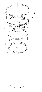
Fig. l shows a set up piece l separate from the can 2.
In Fig. 2 the set up piece l is mounted on the can 2.
The set up piec~ l comprises a substantially cylindri-
cal wall 3 which at its lower end is provided with a rib 4 by
which a tight connection between the set up piece l and the can 2
can be obtained.
1;286~2
- 6;-
The se-t up piece 1 is provided with a bottom 5 which by
means o~ a raised angular portion 6 is connected to the
cylindrical wall 3. Fur~her the bottom 5 i5 having a raised
centre portion 7.
The bot-tom 5 is provided with an opening 8 as particularly
appears from the Figs. 1, 3, 4 and 5, The opening 8 can
cooperate with the opening 9 in the lid 10 of the can 2.
When the set up piece 1 is slid onto the can 2, as in-
dicated in Fig. 2, the set up piece 1 can be rotated in
the direction of the arrow P (Fig. 11 to bring the openings
8 and 9 in line with each other when one wants to drink
out of the can. When the opening 9 has to be closed the
upset piece can be rotated till the openiny 9 is closed
off by the bottom 5 of the set up piece.
The raised centre portion 7 is present to prevent contact
between the bottom 5 and parts 11 (Fig. 1~ which might
be present as part of the means by which the opening
in the lid 10 of the can 2 was originally closed.
As appears from the Figs. 3 and 4 the opening 8 in the
bottom 5 oE the set up piece 1 is surrounded by somewhat
slanted bottom portions 12 which will engage the edge
13 of the opening g in the lid 10 as appears in particular
from Fig. 4. By this it is prevented that droplets of
liquid will be sucked in -the space bet~een the bottom 5
and the lid 10. Further a lit-tle rib 14 is provided
around the rounded off portion of the opening 8 where
this is nearest to the cylindrical wall 3, such that the
height of said rib is decreasing from that place, as
appears from Fig. 3.
Fig. 5 shows the possibility that around -the opening 8
in the bottom 5 of the set up piece a groove 15 is
provided, in which a ring 16 can be positioned, said
ring being made of a resilien-t material.
Figs. 6 and 7 show another embodiment of a set up piece 21
according -to the present invention for mounting on a can
~L2~ 22
-- 7 --
22, which is provided wi1h a flange rim 23 where the
cylindric~l portion 24 oE the can 22 is joined with the
lid 25 of the can.
In this case the opening 26 in -the lid 25 is having a
subs-tantially triangular shape.
The set up piece 21 is having a bottom 27 in which an
opening 28 is provided, the shape of which corresponds
substantially with that of -the opening 26 in the can 22.
The set up piece 21 can be kept on the flange rim 23 by
the cooperating part 29 and 30 extending around the
~ottom 27 of the set up piece 21. The part 29 is an
extension of the cylindrical wall 31 of the set up piece
and the par-t 30 is forming the connection between the
bottom 27 and the cylindrical wall 31.
It will be clear tha-t, after mounting of the set up piece
21 Oll the can 22 the set up piece can be rotated in
respect of the can 22 so that the opening 26 of the can
can be in line with the opening 28 of -the set up piece 21
or can be closed off by the bot-tom 27 of the set up piece
21.
Fig. 8 shows the possibili-ty to place the set up piec~
in upsidedown position on a can 22, so that it will
occupy very little space during transporta-tion and a se-t
up piece 21 can be delivered wi-th a can 22.
It will be clear tha-t the same holds Eor -the embodiment
shown in -the Figs. 1 - 5, al-though in -that case the set
up pieces will take somewha-t more space.
Fig. 9 shows a third embodimen-t of a set up piece 41
having a substan-tially cylindrical wall 42 which at its
lower end is provided wi-th a rib 43 as -this is the case
wi-th the embodiment oE Fig. 1 - 5.
Now -the cylindrical wall 42 is connec-ted to an angular
6c)2~2
-~ -- 8 ~
por-tion 44 which at i-ts inner circumEerence is provided
with a rib ~S The rib 45 can come into contact with the
lid of a can but it will be clear, tha-t in case of this
embodiment the opening in the lid of the can can not be
closed ofE.
It is obvious tha-t the embodiment according to Fig. 9
is cheaper to fabricate and such set up pieces are taking
less space when being stacked.
Although in the Figs. 6 - 8 the shape of the edge of the
opening 28 in the bottom 27 of the set up piece 21 is
not indicated in detail, it will ~e clear that in that
case too the bottom 27 will be shaped such that it is
prevented that liquid will come into the space between
the bottom 27 of the set up piece 21 and the lid 25 of
the can 22. To this end e.g. the features as indicated
in Figs. 3 and 4 can be used.
It has to be remarked that the lower surface of the ~ottom
of a set up piece, that means the surface direc-ted towards
the lid of a can, will not be smooth but somewhat roughenedO
This sometimes is indicated as a "structured" surface.
By this the possibility that liquid is sucked between
this surface and the lid of a can is decreased.