Language selection

Search

Patent 1266102 Summary

Third-party information liability

Some of the information on this Web page has been provided by external sources. The Government of Canada is not responsible for the accuracy, reliability or currency of the information supplied by external sources. Users wishing to rely upon this information should consult directly with the source of the information. Content provided by external sources is not subject to official languages, privacy and accessibility requirements.

Claims and Abstract availability

Any discrepancies in the text and image of the Claims and Abstract are due to differing posting times. Text of the Claims and Abstract are posted:

  • At the time the application is open to public inspection;
  • At the time of issue of the patent (grant).
(12) Patent: (11) CA 1266102
(21) Application Number: 1266102
(54) English Title: ELECTRIC CABLES
(54) French Title: CABLES ELECTRIQUES
Status: Expired and beyond the Period of Reversal
Bibliographic Data
(51) International Patent Classification (IPC):
  • H01B 9/02 (2006.01)
(72) Inventors :
  • BALL, EDMUND HUGH (United Kingdom)
(73) Owners :
  • PIRELLI GENERAL PLC
(71) Applicants :
  • PIRELLI GENERAL PLC (United Kingdom)
(74) Agent: GOWLING WLG (CANADA) LLP
(74) Associate agent:
(45) Issued: 1990-02-20
(22) Filed Date: 1986-07-30
Availability of licence: N/A
Dedicated to the Public: N/A
(25) Language of filing: English

Patent Cooperation Treaty (PCT): No

(30) Application Priority Data:
Application No. Country/Territory Date
8519967 (United Kingdom) 1985-08-08

Abstracts

English Abstract


- 1 -
ABSTRACT
ELECTRIC CABLES
An electric cable having a current carrying
conductor provided with an extruded polymeric insulating
layer, has a layer of a high permittivity material
extruded over the whole length of the insulating layer,
which layer is covered with semi-conducting tape in
contact therewith.


Claims

Note: Claims are shown in the official language in which they were submitted.

The embodiments of the invention in which an
exclusive property or privilege is claimed are defined as
follows:
1. An electric cable having at least one current
carrying conductor provided with an extruded polymer
insulating layer, over the whole length of which is an
extruded layer of material having a relative permittivity
of at least 15, said latter layer being covered with
semi-conducting tape in contact therewith.
2. A cable as claimed in claim 1, wherein said semi-
conducting tape includes a desiccant.
3. A cable as claimed in claim 1, wherein said relative
permittivity is at least 20.
4. A cable as claimed in claim 3, wherein said semi-
conducting tape includes a desiccant.
5. A cable as claimed in claim 1, wherein said
polymeric insulating layer is extruded on to a layer of
semi-conducting material which is extruded over said at
least one current carrying conductor.
6. A cable as claimed in any one of claims 2, 3 and 4,
wherein said polymeric insulating layer is extruded onto
a layer of semi-conducting material which is extruded
over said at least one current carrying conductor.
7. A method of making a joint or termination for a
cable as claimed in claim 1, including stripping back the
semi-conducting tape over said layer of material having a
relative permittivity of at least 15 along an end portion
of the cable but not stripping said latter layer from the
insulation layer of the cable.

8. A method of making a joint or termination for a
cable as claimed in claim 2, including stripping back the
semi-conducting tape over said layer of material having a
relative permittivity of at least 15 along an end portion
of the cable but not stripping said latter layer from the
insulation layer of the cable.
9. A method of making a joint or termination for a
cable as claimed in claim 3, including stripping back the
semi-conducting tape over said layer of material having a
relative permittivity of at least 15 along an end portion
of the cable but not stripping said latter layer from the
insulation layer of the cable.
10. A method of making a joint or termination for a
cable as claimed in claim 4, including stripping back the
semi-conducting tape over said layer of material having a
relative permittivity of at least 15 along an end portion
of the cable but not stripping said latter layer from the
insulation layer of the cable.
11. A method of making a joint or termination for a
cable as claimed in claim 5, including stripping back the
semi-conducting tape over said layer of material having a
relative permittivity of at least 15 along an end portion
of the cable but not stripping said latter layer from the
insulation layer of the cable.
12. A method of making a joint or termination for a
cable as claimed in claim 2, 3 or 4, including stripping
back the semi-conducting tape over said layer of material
having a relative permittivity of at least 15 along an
end portion of the cable but not stripping said latter
layer from the insulation layer of the cable, and
wherein said polymeric insulating layer is extruded onto

a layer of semi-conducting material which is extruded
over said at least one current carrying conductor.

Description

Note: Descriptions are shown in the official language in which they were submitted.


lZ6610Z
ELECTRIC CABLES
This in~ention relates to electric cables, and
more particularly to electric cables in which the
current carrying conductors are provided with extruded
polymeric insulating layers.
In known high voltage cables in which the current
carrying conductors are provided with extruded polymeric
insulation, a layer of polymeric insulation is disposed
over the conductor with a first semi-conducting layer
between the conductor and insulation and a second semi-
conducting layer over the insulation, and a conducting
sheath is provided over the second semi-conducting layer
to provide an earth screen. It is conventional to co-
extrude the semi-conducting layers with the insulating
layer whereby the semi-conducting layers are bonded to
the insulating layer. The purpose of the semi- conduct-
ing layer is to prevent electrical discharges occurring
due to voids bein present between the inner surface of
the insulating layer and the conductor and between the
outer surface of the insulating layer and the conducting
sheath-
The semi-conducting layer over the insulating
layer has to be removed during jointing or termination
of the cable in the region of the joint or termination
as it normally has a resistance such that it would carry
unacceptable high currents if it were allvwed to form a

~2~61~
-- 2
path bet~en the ~rrent ~arr~in~ conductor and earth
in the joint or t~rmination. Remo a~ of the ~emi-
condurtin~ ~a~er o~er the insu]atin~ ]a~r ~herefrom is
a diffjcu]t operation ~hich in ol~es th~ ris~ of damage
b~ing caused to the insu~ation ]a~er.
~ o a~oid this prob]em it has been prop~sed to
pro~id~ o ~r the ~ho~e length of the insu~ation la~er a
~a~er of hi~hl~ resisti e materia] ~lose resistance is
~o~ta~e depend~nt instead of a se~i-conductin~ ~ayer
'~ ~ince ~u~h a ~o~ta~e dependent resisti~ la~er does not
ha~e to be remo~ed d~rin~ jointin~ or termination.
Ho~ er this soluti~n suffers from the disad antage
that material ~ith the appropriate ~oltage dependent re-
sisti~it~ is not suitab~e for application by con ention-
'S a~ extrusion equipment.
~ he present in ention seeks an a3ternati~e solu-
tion in ~hich the semi-conducting la~er o er the insu~-
ating ~a~er is rep~aced b~ an alternati-~e la~er hhich
can be readil~ extruded o er the insulating la~er but
hich does not ha-e t-o be remo ed during jointing or
terminating.
~ he pres~nt in~entio~ provides an electric cable
ha ing at least one current carr~in~ conductor pro~ided
hith an extrud~d pol~meric insulating la~er o~er the
2~ ~hole ~en~th of hhich is an extruded layer. of materia~
having a re]at.ive permitt.ivity of at least 15 said ~atter
~ayer heing co~ered with semi-conducting tape in
contact. there~ith.
The present inverl~ion in another aspect resides
3 in a meth~ ~r making a joint or termination for a cable
as described above including stripping back the semi-
conducting tape over said layer of material having a
relative permittivity of at least 15 along an end portion
of the cable but not stripping said latter layer from the
insulation layer of the cable.

~LZ~
-2a-
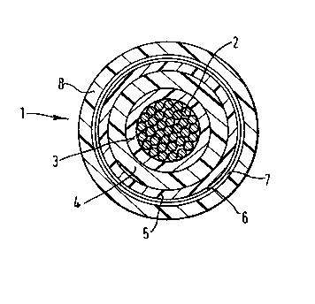
ln order that the invention may be well understood
an embodimen~ t~hereof, hhich is given by h~ay of example
only,h~ no~ be described ~ith reference to the accom-
pan~ing drawing in ~hich the single figure schematica]ly
shohs in radial cross-section a high ~oltage electric
cable. Referring to the figure, the high voltage
~lectric cable ~ has a sing~e current carrying, stranded
.

i6~
conduct.or 2. A ~ayer 3 of semi-cond~cting material i5 ex-
truded o~er the conductor Z. A layer 4 of polymeric in-
sulating material is extruded over the layer 3 of semi-
conducting material and a layer 5 of high permittivity mat-
5 erial, that is a material with a relative permittivity ofat least. 15 and preferably for example 20 to 30, or even
more, is extruded over the layer 4 of insulating material.
All three extruded layers 3,4 and 5 extend the whole length
of the conduct.or 2 and t.he insulating layer 4 is bonded to
1~ the layers 3 and j on each side of it. The three layers
3,4 and 5 may be co-extruded or extruded in separate oper-
ations on t.he cable length.
In order to fulfil its functions of preventing elec-
trical discharges the high permittivity layer 5 is covered
~5 with semi-conducting tape 6 which is lapped or longitudin-
ally wrapped around the high permittivity layer 5 in con-
tact with the outer surface thereof. The semi-conducting
tape 6 may include a desi~cant. Whilst it is preferable
that the entire surface of the high permittivity layer be
~0 contacted by the semi-conducting tape small breaks in
such contact will not give rise to electrical discharges
because of the high permittivity of the layer. A convent-
ional metallic earth screen 7 is provided over the semi-
conducting tape and an outer plastics sheath 8 is provided
over the screen 7.
~ 'hen making a Joint or termination the semi-conduc-
ting tape 6 over the high permittivity layer 5 is
stripped back by simple unwinding or unwrapping thereof
to the termination of the earth screen 7, but since the
high permittivity layer 5 will carry negligble current if
left in a position at a joint or termination, it does not
have to be stripped from the insulation layer 4. This not
only simplifies jointing and terminating operations and
eliminates the possibility of damage to the insulation
layer's outer surface but also assists stress distribution

~ 26
-- 4
within the joint or termination as the high permittivity
layer tends t,o reduce the surface gradient at the earth
screen terminat,ion.
An example of a suitable high permittivity material
j is nitrile rubber containing anatase.

Representative Drawing
A single figure which represents the drawing illustrating the invention.
Administrative Status

2024-08-01:As part of the Next Generation Patents (NGP) transition, the Canadian Patents Database (CPD) now contains a more detailed Event History, which replicates the Event Log of our new back-office solution.

Please note that "Inactive:" events refers to events no longer in use in our new back-office solution.

For a clearer understanding of the status of the application/patent presented on this page, the site Disclaimer , as well as the definitions for Patent , Event History , Maintenance Fee  and Payment History  should be consulted.

Event History

Description Date
Time Limit for Reversal Expired 2000-02-22
Letter Sent 1999-02-22
Grant by Issuance 1990-02-20

Abandonment History

There is no abandonment history.

Fee History

Fee Type Anniversary Year Due Date Paid Date
MF (category 1, 8th anniv.) - standard 1998-02-20 1998-01-28
Owners on Record

Note: Records showing the ownership history in alphabetical order.

Current Owners on Record
PIRELLI GENERAL PLC
Past Owners on Record
EDMUND HUGH BALL
Past Owners that do not appear in the "Owners on Record" listing will appear in other documentation within the application.
Documents

To view selected files, please enter reCAPTCHA code :


To view images, click a link in the Document Description column. To download the documents, select one or more checkboxes in the first column and then click the "Download Selected in PDF format (Zip Archive)" or the "Download Selected as Single PDF" button.

List of published and non-published patent-specific documents on the CPD .

If you have any difficulty accessing content, you can call the Client Service Centre at 1-866-997-1936 or send them an e-mail at CIPO Client Service Centre.


Document
Description 
Date
(yyyy-mm-dd) 
Number of pages   Size of Image (KB) 
Claims 1993-12-07 3 72
Abstract 1993-12-07 1 9
Cover Page 1993-12-07 1 13
Drawings 1993-12-07 1 21
Descriptions 1993-12-07 5 121
Representative drawing 2000-06-08 1 19
Maintenance Fee Notice 1999-03-22 1 179
Fees 1996-01-18 1 34
Fees 1997-01-29 1 35
Fees 1995-01-12 1 40
Fees 1994-01-12 1 30
Fees 1992-12-24 1 14
Fees 1991-12-27 1 38