Note: Descriptions are shown in the official language in which they were submitted.
34~
Folding pocket saws are currently avallable in a wide
variety of formsl and generally consist of a handle in which
at least one blade is pivotably mounted for movement between a
folded or closed position, and an extended or open position in
which i~ is in condition for use. For example, one folding
saw that is commercially available includes a pair of blades
that are mounted direc-tly in the handle and are stored by
folding them into its upper surface; the blades are biased by
a spring washer disposed between them on their pivot screw,
and a slide lock is provided which is received in a recess in
the bottom surface of the handle and is drawn rearwardly to
unlock the blades and permit their movement. Another
commercially available saw has a blade directly pivoted upon
one screw and a latch member pivoted upon a second screw
spaced therefroml the latter acting to lock the blade in
position. Folding knives having slide switches operated from
the side of the handle are of course also commonly known.
There is as well a considerable body of patent art that
is pertinent to the construction of tools having folding
blades. Thus, Chilko U. S. Patent No. 3,404,456 discloses an
over-center spring loading arrangement for the folding b:Lade
of a saw, by which it is held in either the open or the closed
position. A spring loaded lever is employed in the tool shown
in Montgomery U.S. Patent No. 981,786, which functions to lock
the blade in either o~ two open, as well as its closed,
position. A pruning saw with a spring-loaded locking bolt is
disclosed in Santoyo U.S. Patent No. 1,638,749, and in U.S.
Patent No. 692,092 Upham shows a pocket knife with folding
blades, which apparently are held in position by conventional
spring loading means.
2--
~2~i3~2
Each of the following U.S. patents utilizes some form oE
mechanical lock to retain a blade in extended position:
Finlay Des. No. 257,943; I~oskela No. 2,736,354; Behlefeldt No~
2,747~631 (mul~iple blade positions); Do~7dy et al No.
2~904/373 (a wa~er-tight compartment also being provided
within the handle); Herman e~ al No. 3,245,445; and Bush No.
25~,l79. Tyler U.S. Patent No. ~98,754 sho~s a folding saw in
which the blade is partially received within the handle, and a
combination tool is disclosed in Haag U.S. Patent No. 784,674,
which has a saw blade formed with apertures to receive a
detent for locking it in each of several pivoted positions.
European Patent Application No. lO0 377 discloses a folding
knife construction in which a number of blades rotate about a
common pivot, spring action being employed to hold them in
open or closed positions, and German OffenlegungsschriEt DE 33
24 637 discloses a folding pocket knife construction in which
a spring loaded member cooperates to secure the blades.
Despi~e the rather ex~ensive activity in the art
indicated by the foregoing, a need remains for a sturdy and
durable pocket tool, which is reIatively facile and
inexpensive to manufacture and in which interchangeable blades
of various types can readily and securely be mounted, for
movement be~ween open and closed positions and for highly
effective use.
Accordingly, it is an object of the present invention to
provide a novel handle assembly for a tool having
interchangeable fold-away blades, which is sturdy and durable
and yet relatively facile and inexpensive to manufacture.
It is also an object of the invention to provide such a
handle assembly in which blades of various types can readily
3'72
and securely ~e mounted for highly effective and convenient
use.
It is another object of the invention to provide such an
assembly wherein the head member on which ~he blades are
mounted can be secured in both its open and closed positions
in a si~ple and yet effective manner, and from which the
mounted blade can conveniently be unfolded to its operative
position.
Yet another object of the invention i9 to provide such a
handle assembly wherein the body of the handle serves not only
to contain the folded blade but also to store a supply of
replacement blades.
Additional objects concern the provision oE a novel tool
employing a handle assembly having the foregoing features and
advantages.
It has now been found that certain of the fore~oing and
related objects of the invention are readily attained by the
provision of a handle assembly for a tool having
interchangeable, fold-away blades, comprising an elongated
body adapted to be hand held, and a tool-supporting head
member pivotably mounted adjacent the forward end o the body.
The head member pivots about a transverse axis between an
operative position, in which a supported blade extends axially
outwardly of khe body, and a storage position in which the
blade is folded inwardly along the underside thereof. The
assembly also includes means on the body for engaging the head
member against rotation about the transverse axis in both of
its positions~ the head member having means thereon for
disengageably aEfixing each of a plurality of different blades
thereto for operation by the handle assembly.
4--
~2~37~
Generally, the head member will be mounted within the
body, which will have an opening extending longitudinally
along the forward end and tne underside thereof to permit
rotation of the head member with a blade affixed to it~
Normally, the body will have an elongatecl cavity in its lower
portion, which is coextensive with the ope:ning along part of
its length, and i5 adapted for the substantial containment of
a blade affixed to the head member. The body will
advantageously be substantially hollow, ~ith an internal web
element extending laterally and longitudinally thereof to
provide the lower wall of a blade storage chamber, an opening
being formed in the body to permit the insertion and
withdrawal of blades into and from the storage chamber and a
displaceable closure being provided thereon for covering the
opening; in such a construction, the web element that defines
the lower wall of the storage chamber may also define the top
of the containment cavity. The body will generally include an
abutment component upon which the head member rests in its
operative position.
In the preferred embodiments, the engaging means will
comprise a locking member and the head member will have
elements theraon adapted for engagement therewith, the locking
member being movable to and from a position of engagement to
restrain rotation of the head member from the extended
position toward the folded position, and vice versa. The head
member may have a peripheral edge portion configured to
provide the engaging elements, which may comprise surface
elements disposed to opposite sides of the transverse axis of
pivoting. More particularly, one of the surface elements will
desirably extend generally along a diametrical axis taken
:, .
3~
through the transverse pivo-tal axis, with the other element
extending generally perpendicularly thereto. In its
engagement position, the locking member will bear upon the
"one" surface element of the edge portion in the folded
position of the head member, and will bear upon the "other"
surface element in the open position thereof~ the surface
elements being so disposed on the member that each lies above
the transverse axis when the locking member bears thereupon.
The locking member will normally be mounted in the upper
portion of the body for sliding movement along a longitudinal
axis, and i-t will most desirably have a shoe portion with
first and second surEace elements perpendicularly disposed on
its lower forward part to bear, respectively, upon the "one"
and l'other" surface elements of the head member. To cooperate
therewith, the section of the peripheral edge portion of the
head member/ lying between the engaging elements thereoE, will
advantageously be of arcuate configuration, and will have the
"one" surface element extending inwardly therefrom along the
diametrical axis to provide a shoulder element at the juncture
therebetween. The assembly will usually include means for
biasing the locking member forwardly on the body, thereby
urging the "first" surface element of the shoe portion against
~he "one" surface element of the head member to maintain the
folded position thereof, the locking member being displaceable
rearwardly against the biasing means by manual force applied
to pivot the head member from its folded position, such Eorce
being transmitted by contact of the shoulder element of the
head member upon the "first" surface of the shoe portion. The
latter will ride upon the arcuate peripheral edge section of
the head member, during its movement subsequent to such
~',"~
displacement of the locking member, and the lower Eorward part
of the shoe portion will preferably be formed with a
transition surface elemen-t extending between the
perpendicularly disposed surface elements thereof, the
transition element bearing upon the arcuate section during
such subsequent movement.
The surface elements of the head member may be provided
by a pair of generally L-shaped notches formed into its
periphery, each of the notches providing a radial surEace
elementl extending along the diametrical axis, and a chordal
.sur:Eace element extending perpendicularly thereto from the
inner end of the radial e.l.ement, the chordal elements being
equidistantly spaced from the transverse pivotal a~is. To
cooperate with such a construction, the shoe portion of the
locking member will seat within the notches in both the
operative and also the folded positions of the head member.
Usually, the locking member will include a button portion that
lies outwardly of the body and is accessible for finger
actuating contact.
The head member may, even more specifically, comprise a
head piece having a recess formed into one side and extending
to the peripheral edge thereof, with a tongue protruding into
the recess adjacent its inner end and a transverse aperture
therethrough; a clamping piece having a transverse aperture
aligned with the aperture of the head piece; and a removable
fastener extending through the apertures and disengageably
securing the head piece and clampiny piece together. The head
piece and clamping piece will cooperatively provide the means
for affixing blades on the head member, and will be adapted to
secure blades having an end portion configured to seat within
~IE;G3~Z
the recess of the head piece in engagement with khe protruding
tongue, and to receive the fastener therethrough. Thus, the
head member will support such a blade at two points, as well
as clamping it between the head piece and the clamping piece
of which it is co}nprised.
Other objects of the invention are attained by the
provision of a tool including a removable blade and a handle
assembly. The latter will be constructed as described herein,
and will have the various features set forth.
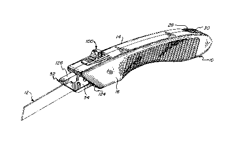
Figure 1 is a perspective view of a Eolding saw embodying
the present invention, showing the saw blade in phantom :Line;
Figure 2 is a plan view of the saw of Figure l;
Figures 3 and 4 are, respectively~ front and back end
views of the saw;
Figures 5 and 6 are, respectively, views of the opposite
sides of the saw;
Figure 7 is a bottom view thereof;
Figure 8 is a fragmentary exploded perspective view of
the forward end portion of the saw of the foregoing Figures~
showing two styles of blades adapted for mounting on the
handle assembly;
E'igures 9 and 10 are elevational views of the opposite
sides of the blade mounting subassembly utilized in the saw,
fragmentarily illustrating the mounted blade;
Figure 11 is a sectional view of the mounting subassembly
illustrated ln Figures 9 and 10, taken along line 11-11 of
Figure 10 and drawn to a scale enlarged therefrom;
Fiyure 12 is an elevational view of the saw of the
foregoing Figures, with one side of the handle casing removed
to show internal construction and also showi.ng the storage of
extra blades therewi~hin;
--8
ii372
Flgure 13 is a fragmentary elevational view of the saw,
taken at the forward end of the handle and showing the
mounting subass2mbly in a position intermediate the folded and
Fully extended positions thereof;
Figure 14 is a similar fragmentary elevational view
showing the blade opened to its operative position;
Figure 15 is a sectional view taken along line 15-15 of
Figure 12; and
Figure l6 is a fragmentary elevational view of the back
end of the handle, with a portion o~ the casing broken away -to
show the blade storage chamber provided therewithin.
Turning now in detail to the appended drawings, therein
illustrated is a ~oldiny pocket saw embodying the present
invention and consisting of a handle generally designated by
the numeral lO, a saw blade generally designated by the
numeral 12, and a blade mounting subassembly, including a
pivotable head generally designated by the numeral 52. The
handle is dimensioned and configured -to be held comfortably by
the user, and consists of two mated sections 14, 16, which
will generally be molded of a suitable tough plastic material.
As is best seen in Figures 12-16, the handle body or
casing is substantially hollow, and both sections are formed
with a pattern of internal web elements 18, which serve to
reinforce the handle. In addition, two web elements 20, 22 on
each of the casing halves cooperatively form laterally and
longitudinally extending walls, which span the handle and are
spaced from one ano~her to define therebetween, in cooperation
with the forward wall element 24, an internal chamber 26 for
the storage of spare blades 1~ (as seen in Figure 12). A
rectangular hatch 28 is formed through the top wall of the
3~
handle, and a door 30 is slidably supported in the lateral
channels 32, defined by longitudinal ribs 34, to guide the
door between open and closecl positions over the hatch. The
door 30 has a tab 36 along one edge, which serves as a handle
for slidiny it ~ack ancl forth, and it has a small rib 38 along
its opposite edget the rib snaps into the groove 40, formed
into the body along the upper margin of the hatch 28, to
maintain the door 30 in its closed position.
As will be appreciated, the two sections of the handle
are substantially mirror image forms of one another. One
structural difference between them, however, resides in the
provision of laterally extending pins 42 on section ]4, and
mating hollow bosses (not shown) on section 16, the pins being
received within and ultrasonically bonded to the bosses to
permanently assemble the handle. Similarly, and as is best
seen in Figure L5, section 14 has a relatively large diameter
laterally extending post 44 adjacent its forward end, and the
opposite part 16 has a socket 46 thereon within which the
outer end 45 of the post 44 is seated~ The post 44 serves as
the axle upon which the blade mounting subassembly is
supported, and the circular formations 48, 50, provided at the
base of the post 44 and boss 46, respectively, provide bearing
surfaces thereEor~
The mounting subassembly ikself consists of the head 52,
a clamping plate 54, and a screw 56 which fastens the other
two parts together. The head 52 has a forward portion 5~,
into one side of which is formed an irregularly shaped recess
60, extending to the inclined edge 62 thereof. A small tongue
64 projects into the recess 60, and an aperture 66 is formecl
through the head at a point spaced forwardly from the tongue
6~.
~10-
The clamping piece 54 has a peripheral coniguration that
is essentially identical to that of the recess 60 in the head
52, to seat snugly therewithin. It also has a threaded
aper~ure 68 extending through it, iocated to align with the
aperture 660 As will be appreciated, the saw blade 12, 12'
(see Figure 8) is affixed on the mounting subassembly by
placing its inner end portion 70 into the recess 60 with its
aperture 72 aligned with apertures 66, 68 of the piece~ 52,
54. In the case of the larger blade 12, the inner end portion
70 terminates in a tang element 7~ of reduced width, which
engages under the tongue 64 in its inserted position.
Consequently, when the screw 56 is engaged within the aligned
apertures 66, 58, 72, two-point support for the blade, secured
by the clamping of piece 54 thereupon, is provided. The
smaller of the two blades shown in Figure 8 has a semicircular
notch 76 formed into the back edge of its innermost end 70,
which engages the rounded tip of the tongue 64 when the blade
12 is properly positioned wi~hin the recess 60, again
providing two-point support for the blade. It will be
appreciated that the head 52 may be formed with secondary
recesses ~not illustrated) within the main recess 60, shaped
to provide additional supporting elements along the edges of
the saw blade, iE so desired.
The rearward or inner end portion 78 of the head 52
(considering it in its operative position) has a circular edge
section 80 which is coaxially disposed with respect to the
aperture 82, the latter receiving the post 44 for pivotal
mounting of the subassembly. The periphery of the head 52 is
formed with a pair of L-shaped notches or steps at the ends of
the circular section 80, which provide radially extending
~ 3~72
surface elements 84, 86,.and chordally extending elements 8B,
9U prependicular to the elements 84, 86 (and to an imaginary
diametrical axis drawn therethrough and through the center
point of the aperture 82); a shoulder element 92 is formed at
the intersection of the radial surface element 84 and the
circular edge section 80.
As seen in Figure 10, one side of the head 52 is Eormed
with an annular recess 94 about the aperture 82, in which ls
seated a spring washer 96. The washer 96 produces an axial
1~ bias upon the head 52, thus minimizing any tendency that:might
exist for looseness or wobbling of the mounting subassembly
withi.n the handle.
The upper wall components of the two casing halves 14, 16
are indented to cooperatively define a small rectangular
opening 98, within which is mounted a push-button slide lock,
generally designated by the numeral 100. The lock in turn
consists of a button portion 102 and a lockin~ shoe portion
104, the latter having slot formations 106 along its opposite
sidesO Each of the two body sections 14, 16 has a flange
element extending longitudinally along its inside surface
adjacent the indent for the opening 98, the marginal portions
of which are engaged within the slot formations 106 of the
shoe portion 104; thus, the lock 100 is slidably mounted for
longitudinal movement within the opening 98. A short stud 110
projects rearwardly from the back of the slide lock, on which
is mounted a coil spring 112~ The latter bears upon the small
internal end wall 114, and serves to urge the lock 100 in the
forward direction.
~ 5 iS perhaps most clearly illustrated in Figures 12-14,
the lower forward part of the shoe portion 104 is configured
-12-
to provide perpendicular forward and bottom faces 116, 118,
respectively, joined by an oblique trans.it.ion surface 120
disposed therebetween. In the extended, operative position of
the blade (shown in Figures 1-7 and 14). the forward portion 58
of the head 52 projects through the section of the
longitudinal slot 122 that extends along the forward, inclined
surface 124 of handle body. The upper edge 126 of the head 52
bears not only upon the overlying surface 128 at the top of
the slot 122, but upon the transverse abutment element 130
formed on the body section 14, as well. Thus/ sturdy support
is provided :Eor the saw blade to resist the downward force
applied in cutting the workpiece.
In that position of the blade~ the shoe portion 104 of
the lock 100 is also wedged between the top wall section 109
of the handle and the head 52 with the bottom surEace 118 of
the shoe portion bearing upon the chordal surface 90, as seen
in Figure 14. Release oE the blade-mounting subassembly is
effected simply by drawing the lock 100 rearwardly against the
: bias of the coil spring 112, to disengage the sur:Eaces 90,
118.
The folded position of the blade is illustrated in Figure
12, from which it can be seen that the head subassembly has
been rotated through an angle of 180 from the extended
position, thereby presenting to the lock 100 the notch on the
opposite side of the head 52. When the shoe portion 104 is
returned to its advanced position and seated within the notch,
the surface element 116 at the forward end thereof is brought
to bear upon the radial surface element 84, thereby
maintaining the blade 12 in position within the internal
cavity 124, which is defined by the wall 20 and the sides of
the casing sections 14, 16. It will be appreciated that the
slot 122 extends along substantially the entire length of the
handle body to permit passage of the blade and head
subassembly, as described.
To extend the blade, it is merely necessary to yrasp it
(as will be facilitated by the inward curvature of the lower
portion of the handle) and pivot it downwardly. This will
cause the shoulder element 92, formed at the end of the
circular edye section 80 of the head 52, to bear upon the
surface element 116 of the shoe portion 104, in turn forcing
the lock 100 rearwardly; i.e., in this condition oE the head
the lock ~unctions as a non-positive detent. After pivoting
through a relatively small arc, the shoulder element 92 will
pass to the oblique transition surface element 120, which will
thereafter ride upon the circular section 80 until the chordal
element 90 is presented to the locking shoe portion, whereupon
the operative position will be reestablished; the relationship
of the parts in transi~ion is illustrated in Figure 13.
As will be appreciated, the handle assembly described
herein is not only suitable for use with a variety oE
different saw blades, but also with other types of blades,
such as of knives, razors, and the like. The materials
employed for construction Qf the several parts of the device
will be evident -to those skilled in the art, plastics and
metals generally being most advantageously used. Finally,
although the configuration of the handle body illustrated is
highly desirable from the standpoint of comfort and aesthetic
appeal, it will be appreciated that considerable variation
therein, as well as in the nature and placement of the locking
buttonr is possible.
-14-
:: .
dF~%
Thus, it Call be seen that the present invention provides
a novel handle assembly for a ~ool having interchangeable
fold-away blades. The handle assembly is sturdy and durable,
and yet relatively facile and inexpensive to manufacture, and
it readily permits the secure mounting of blades of various
types for highly effective and convenient use. The head
member on which the blades are mounted can be secured in both
its open and closed positions in a simple and ye~ effective
manner, and the body of the handle serves not only to contain
the folded blade but also to 9 tore a supply thereof. In
addition, the invention provides a novel too]. employing a
handle assembly having the foregoing Eeatures and advantages.
-15-