Language selection

Search

Patent 1266393 Summary

Third-party information liability

Some of the information on this Web page has been provided by external sources. The Government of Canada is not responsible for the accuracy, reliability or currency of the information supplied by external sources. Users wishing to rely upon this information should consult directly with the source of the information. Content provided by external sources is not subject to official languages, privacy and accessibility requirements.

Claims and Abstract availability

Any discrepancies in the text and image of the Claims and Abstract are due to differing posting times. Text of the Claims and Abstract are posted:

  • At the time the application is open to public inspection;
  • At the time of issue of the patent (grant).
(12) Patent: (11) CA 1266393
(21) Application Number: 1266393
(54) English Title: ADJUSTABLE MEANS FOR PROFILE CORRECTION FOR A HEADBOX SLICE
(54) French Title: DISPOSITIF DE REGLAGE POUR CORRIGER LA CONFIGURATION DE LA LEVRE DE LA CAISSE D'ARRIVEE
Status: Expired and beyond the Period of Reversal
Bibliographic Data
(51) International Patent Classification (IPC):
  • D21F 01/02 (2006.01)
  • D21F 01/06 (2006.01)
(72) Inventors :
  • COOK, WILLIAM GEORGE (United States of America)
(73) Owners :
  • TAMPELLA SANDY HILL, INC.
(71) Applicants :
  • TAMPELLA SANDY HILL, INC. (United States of America)
(74) Agent: OSLER, HOSKIN & HARCOURT LLP
(74) Associate agent:
(45) Issued: 1990-03-06
(22) Filed Date: 1987-03-17
Availability of licence: N/A
Dedicated to the Public: N/A
(25) Language of filing: English

Patent Cooperation Treaty (PCT): No

(30) Application Priority Data:
Application No. Country/Territory Date
06/876,756 (United States of America) 1986-06-20

Abstracts

English Abstract


ADJUSTABLE MEANS FOR PROFILE CORRECTION FOR A HEADBOX SLICE
ABSTRACT OF THE DISCLOSURE
At the slice region of a headbox of a papermaking machine,
an upper lip is extended across the machine width above the
area where the stock suspension is charged onto the forming wire.
To the lip is secured a profiling member with a portion thereof
being extendable into the throat of the stock passage. The
member has spaced upstanding arms. Inwardly-facing coaxially-
aligned bolting extends through each arm and the pair thereof
support a rectangular open frame. A load is disposed within
the frame so as to be spaced from any side thereof, being
supported on each side by the bolting. A self-contained force
couple may be generated against the load in the form of equal
forces in opposite directions.


Claims

Note: Claims are shown in the official language in which they were submitted.

The embodiments of the invention in which an exclusive
property or privilege is claimed are defined as follows:
1 In a headbox for a papermaking machine having a slice
spaced upwardly of an apron and defining a slice opening
therebetween through which a fluent fibrous stock is delivered
from the headbox to a traveling surface of a continuously-moving
looped foraminous forming member,
a slice nozzle for correcting profile comprising:
a profiling nozzle stationarily secured to the slice and
extendable across the machine width and having a
lowermost extremity extended downwardly into the slice
opening,
the profiling nozzle having spaced upwardly extending arms,
inwardly facing bolting extending through each spaced arm
and being coaxially-aligned as to each other,
a rectangular-shaped open frame disposed inboard of the spaced
arms and supported therefrom by means of the bolting
extendable through two opposite sides of the frame,
a load held in spaced relation to the opposite sides of the
frame by means of the bolting extendable into said two
opposite sides of the load,
means positioned parallel to the bolting for generating a
self-contained force couple upon the load in the form
of equal forces in fore and aft directions,
the profiling nozzle in combination with the load and means
for generating the self-contained force couple being
structured so that the slice does not contribute to any
deflection in any other machine component.
2. In a headbox for a papermaking machine having a slice
spaced upwardly of an apron and defining a slice opening

therebetween through which a fluent fibrous stock is delivered
from the headbox to a traveling surface of a continuously-moving
looped foraminous forming member, comprising;
a profiling nozzle stationarily secured to the slice and
projecting downwardly into the slice opening,
the profiling nozzle having spaced arms,
inwardly facing bolting extending through each spaced arm
being coaxially-aligned as to each other,
a rectangular-shaped open frame disposed inboard of the arms
and supported therefrom by means of the bolting extendable
through two opposite sides of the frame,
a load held in spaced relation to the opposite sides of the
frame by means of the bolting extendable into the two
opposite sides of the load,
means located parallel to the bolting for generating a
self-contained force couple upon the load in the form of
equal forces in fore and aft directions,
the profiling nozzle in combination with the load and means
for generating the self-contained force couple being
structured so that the slice does not contribute to any
deflection in any other machine component.

Description

Note: Descriptions are shown in the official language in which they were submitted.


3~3
B~CKGROUND OF THE INVENTION
1. FIELD OF THE INVENTIOU:
In the maTIufacture of most paper grades, a desideratum is
to provide a mechanisrn for adjusting the discharge of the fluent
system or stock onto the forming wire for controlling profile~
The need for an adequate mechanism is dictated by the
difficulties inherent in the building of a headbox capable of
providing a so-called perfect je~ across the machine width, i.e~
a jet which discharges free of variations in terms of both
quantity and speed across the machine. The width measurement,
incidentally, grows with each successive generation of
sophisticated papermaking ~achinery, widths of up to 400" now
being commonplace.
The front wall beam of a headbox deines the component
which carries the upper lip structure constituting the upper
edge o the slice. Reformation of such a front wall beam or
~eflection thereof will influence the geometry of the lip slice
and therefore the transverse proile or cross section of the
stream of pulp stock flowing through the slice onto the wire.
2, DESCRIPTION OF THE PRIOR A~T:
Varivus earlier patents have been known to approach the
broad problem from different angles.
United States Letters Patent #3j769,154 to Wolf,
#399769539 to Kirjavainen, and ~49008,123 also to Kirja~ainen~
each relate to the matter of compensating for inherent deflec-
tlons in the sl~ce area, these deflections being resultant from
the very weight or stiffness of tl~e slice structure, or ~he
operating pressure under which the headbox is operative.
In times past9 manual profiling has been achieved by the
mechanical deEormation of the slice lip, that is the uppler

~ 3~ 3
portion or roof of the discharge orificey through the use of
spaced jacks posit;oned on and between the slice lip and some
suitably near stationary surface. Ac~uation of ~he jacks was
sufficient to deform the slice lip
As computerized profile controlling became known~ differen~
mechanisms were incorporated into the jacking system as witness
United States Letters Patent ,~4,406,740 to Brieu and ~4,505,779
to Boissevain~
The computer controlled systems have brought with themselves
a problem only partly remedied and not totally eliminated thereby.
That problem relates to the influence which one adjustment
mechanism tends to exert on adjacent mechanisms~ That is to say,
when one jack is adjusted or corrected, neighboring jacks are
affected. A simple correction in one jack compounds itselE in a
correction or recorrection of perhaps two or three or Eour or
more other jacks, the damaging results being obvious.
SUMMARY OF THE INVENTION
The objectionable phenomenon is due to the force couple
involved when the jack is connected betwe-en the slice lip
(sometimes called the profile bar) and the cross machine beam
or other fixed appurtenance, the couple being defined as a
system of ~wo parallel forces of equal magnitude and opposite
sense when the total force of the couple is zero with the tokal
moment of the couple being identical about any point.
In the instance of a force couple~ the force at the 51ice
lip will have an equal opposite force at the beam or other
stationary component and the forces will be such as to defl2ct
the beam or the lip or both for the reason that these members
cannot be made of infinite stiffness~
As one adjus-tment is made; the beam, for example, will
deflect from an earlier position, obv:iously disrupting the
adjustments of one or more oE the previously set jaclcs.

~ 3 ~ 3
Th;s inven~ion eliminates the force collple between the
slice lip and fixed beam~ the force couple now being confined
to the slice area, a feature emanatLng from the theory that
with a force couple being so self-contained the slice lip
cannot contribute to any deflection in the cross beam or
other fixed member. Under such a restriction, the tendency
resultant from a jack adjustment to influence any adjustment in
any adjacent jack is minimized~ if not eliminated.
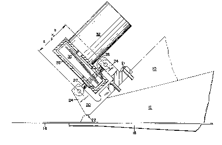
The Figure is a schema~ic diagram of a
slice lip incorporating the invention's
essentials.
DESCRIPTION OF THE PREFERRED EMBODIMENI
A headbox slice 10 in the form of the roof of a passage or
nozzle 12 for the delivery of a fluent stock or slurry to ~he
forming wire 1~ at the terminus of the usual headbox apron 16
is provided at its outboard extremit~ with a generally U-shaped
profiling nozzle 20S the lowermost extremity of which is extended
into passage 12 to define a slice lip 22 which determines the
thickness of the stock flowing ~rom passage or nozzle 12 onto
the forming wire. It may be adjusted at different spaced pOiTltS
along its length across the machine width.
Profiling nozzle 20 is fixed relative to headbox slice 10
as by bolting 21 and extends lengthwise across the machine
width, being strategically fixed relative thereto at spaced
points thereacross by means of the bolting~
Spaced arms 249 24 of profiling nozzle 20 are each provided
with sets of inwardly~facing coaxially aligned bolting 26, 26,
which bolting supports a rectangularly-confîgured open frame 28
;n the center of which frame and in spaced relation thereto a
load 30 is supported by the bolting in spaced relation to the
frame.

~6~3~3
A force F may be generated manually or, as shown~ by means
of a servo unit 32 interconnected with load 30 disposed in
spaced parallelisrn with bolting 26~ 26 as a force couple in the
fore and aft directions as designated by letters a and b~ The
couple is formed by forces a and b7 they being equal but acting
in cpposite directions so that the result~nt equals zero. In
other words, the two forces have no resultant, ergo their
designation as a couple.
In this manner, the force couple will thus be seen to be
restricted to the slice area per se and treated as self-contained
meaning that the slice does not contribute to any deflection
in any other rnachine component, the very desideratum of the
invention.
Being so, any adjustment of the slice opening made manually
or made with the aid of the servo unit will be observed to have
practically no influence on the setting of the slice at any
adjacent adjustment means. That is, the forces are isolated in
the nozzle per se9 eliminating any influence on other components
of the paper machine.
Thus a state of balance exists between the forces. That is,
a state of static equilibrium is attained, the term being used
in its dynamical sense.

Representative Drawing
A single figure which represents the drawing illustrating the invention.
Administrative Status

2024-08-01:As part of the Next Generation Patents (NGP) transition, the Canadian Patents Database (CPD) now contains a more detailed Event History, which replicates the Event Log of our new back-office solution.

Please note that "Inactive:" events refers to events no longer in use in our new back-office solution.

For a clearer understanding of the status of the application/patent presented on this page, the site Disclaimer , as well as the definitions for Patent , Event History , Maintenance Fee  and Payment History  should be consulted.

Event History

Description Date
Inactive: Agents merged 2013-10-10
Letter Sent 2002-03-11
Inactive: Adhoc Request Documented 1997-03-06
Time Limit for Reversal Expired 1996-09-06
Letter Sent 1996-03-06
Grant by Issuance 1990-03-06

Abandonment History

There is no abandonment history.

Owners on Record

Note: Records showing the ownership history in alphabetical order.

Current Owners on Record
TAMPELLA SANDY HILL, INC.
Past Owners on Record
WILLIAM GEORGE COOK
Past Owners that do not appear in the "Owners on Record" listing will appear in other documentation within the application.
Documents

To view selected files, please enter reCAPTCHA code :


To view images, click a link in the Document Description column (Temporarily unavailable). To download the documents, select one or more checkboxes in the first column and then click the "Download Selected in PDF format (Zip Archive)" or the "Download Selected as Single PDF" button.

List of published and non-published patent-specific documents on the CPD .

If you have any difficulty accessing content, you can call the Client Service Centre at 1-866-997-1936 or send them an e-mail at CIPO Client Service Centre.

({010=All Documents, 020=As Filed, 030=As Open to Public Inspection, 040=At Issuance, 050=Examination, 060=Incoming Correspondence, 070=Miscellaneous, 080=Outgoing Correspondence, 090=Payment})


Document
Description 
Date
(yyyy-mm-dd) 
Number of pages   Size of Image (KB) 
Abstract 1993-09-17 1 24
Claims 1993-09-17 2 75
Drawings 1993-09-17 1 25
Descriptions 1993-09-17 4 179
Representative drawing 2001-11-13 1 16
Fees 1994-03-01 1 74
Fees 1995-02-27 1 42
Fees 1993-03-04 1 41
Fees 1992-03-05 1 48