Note: Descriptions are shown in the official language in which they were submitted.
BACKGROUND OF THE INVENTION
Field of the Invention
The subject invention is generally directed to gerotor
hydraulic devices that can be used as pumps and motors and, more
specifically, to hydraulic balancing of moving parts in such
devices.
Description of the Prior Art
Many types of prior art hydraulic devices have
incorporated gerotor, or internal gear sets. Such devices have
been used and described as both pumps and motors. Examples are
shown in U.S. Patents 3,572,983; 4,411,607; and 4,545,748~
Briefly, an internal gear having outwardly directed teeth
cooperates with either an external gear having inwardly directed
teeth or, alternatively, an external ring that is maintained in
an outer housing. The internal gear and external gear or ring
defined fluid chambers. The internal gear and external gear or
ring have a different number of teeth and are sized such that the
fluid chambers expand and contract as the gears rotate. Thus, a
basis for conversion between fluid pressure and mechanical torque
is provided.
In such gerotor devices, as in other hydraulic devices,
it is important that moving components be hydraulically balanced.
Unbalanced components are subject to excessive friction and
-- 2 --
asymmetrical movement~ Excessive friction accelerates mechanical
wear and shortens the useful life of the device. Asymmetrical
movement such as tilting, eccentricity, or skewing increases
hydraulic leakage and friction which reduces mechanical
efficiency and compromises the operating efficiency of the
device.
As with other types of hvdraulic devices, gerotor, or
internal gear, pumps and motors require hydraulic balancing to
achieve high efficiency and to realize their useful working life.
To attain good performance, internal gear devices generally use a
type of rotary face valve that employs lapped surfaces to effect
tightly controlled clearances. However, the tight clearance of
such rotary valves demands that the rotary valve be hydraulically
balanced.
In the prior art, the rotary valve was usually balanced
through the use of a fixed plate that separated the displacement
element from the rotary valve. One example of such a fixed plate
is shown and described in U.S. Patent 3,572,983. In that patent,
the hydraulic force generated by the chambers on one half of the
displacement element is absorbed by one side of the fixed plate.
The opposite side of the fixed plate absorbs the hvdraulic forces
developed by the high pressure ports of the rotary valve.
Pressure areas are also provided on the valve side of the fixed
plate to accomplish additional hydraulic balancing of the valve.
Other types of gerotor devices that employ a rotary
valve have eliminated the need for a stationary plate. An
example of a gerotor device having such a rotary valve is shown
in U.S. Patent 4,545,748. However, in rotary valve type gerotor
devices without the fixed plate mentioned above, the rotary valve
is subject to the hydraulic forces from both the displacement
~ 3
element chambers and the high pressure commutator ports. These
forces place the rotary valve in a condition of hydraulic
imbalance. Accordingly, compensation fox the hydraulic forces
acting on the rotary valve have been found to improve the
efficiency and extend the operational li:Ee of the device.
A technique for partial balancing of the rotary valve in
a gerotor device is shown in U.S. Patent 4,411,607. In that
patent, recessed sections and grooves are provided in the rotary
valve face that is adjacent the commutator ports. The recessed
sections and grooves are said to be arranged so that they develop
a counterforce that opposes the force exerted on the rotary valve
by the displacement element chambers. However, in the prior art,
there was no mechanism for counterbalancing the force on the
rotary valve from the high pressure commutator ports.
Accordingly, there was a need in the prior art for a
mechanism to more completely hydraulically balance the rotary
valves in gerotox devices. In addition, it was recognized that
more complete balancing of other moving components in the gerotor
device would further improve efficiency and performance.
SUMMARY OF THE INVENTION
In accordance with the subject invention, a gerotor type
hydraulic device includes a body that has a fluid inlet and a
fluid outlet. The body also includes a commutator face that has
a plurality of high pressure ports that communicate with the
fluid inlet and a plurality of low pressure ports that
communicate with the f~uid outlet. A displacement gear set that
includes an outer member and an inner member has one side that is
connected to the body. The inner member is located radially
inwardly of the outer member such that the inner member and the
-- 4
outer member cooperate to define a plurality of fluid chambers.
A shaft is coupled to the inner member of the gear set and is
rotatable therewith. Also, a valve plate is located between the
gear set and the pressure ports of the body. The valve plate is
connected to the shaft and rotates therewith. The valve plate
cooperates with the displacement gear set to define at least one
balancing cavity therebetween. Also, the valve plate includes a
plurality of windows and a plurality of through holes. The
windows are regularly spaced in a substantially circular array
and the through holes are located at substan~ially regular
angular positions between the windows. The through holes form
passageways between the pressure ports of the body and the
balancing cavi~y defined between the gear set and the valve
plate.
Preferably, the balancing cavity defined by the gear set
and the valve plate is located either between the valve plate and
the outer gear member or between the valve plate and the inner
~ear member. Alternatively, balancing cavities can be defined
between the valve plate and both the outer and inner gear
members.
More preferably, the balancing cavity between the valve
plate and the gear set is defined by a recessed area in the valve
plate that cooperates with the outer gear, or a recessed area in
the inner gear that cooperates with the valve plate.
Most preferably, the device further includes a cover
that is located on the side of the gear set that is oppositely
disposed from the body. The inner member cooperates with the
cover to define at least one counterbalancing cavity. The inner
~ember al50 includes at least one bore that provid~s fluid
communication between the counterbalancing cavity and the
balancing cavity defined by the valve plate and the gear set.
-- 5
Other details, objects and advantages of the invention
will become apparent as the following descriptlon of a presently
preferred embodiment proceeds.
BRIEF DESCRIPTION OF THE DRAWINGS
The accompanying drawings show a presently preferred
embodiment of the subject invention in which:
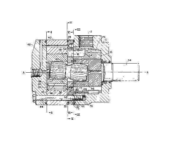
Figure 1 is a cross sectional view of the presently
preferred embodlment taken along the axis of rotation A-A'.
Figure 2 is a crQss section of the embodiment of Figure
1 taken along the lines II-II and showing the inner and outer
gears of the displacement element.
Figure 3 is a cross section of the embodiment of Figure
1 taken along the lines III-III and showing the commutatcr ports
in the body.
Figure 4 is a cross section of the rotary valve of
Figure 1 shown in isolation and illustrating various hydraulic
forces acting on the valve.
Figure 5 is a view of the rotary valve shown in Figures
1 and 4 taken along the lines V-V of Figure 1 and showing the
face of the rotary valve that is adjacent the displacement
element.
Figure 6 is a view of the rotary valve shown in Figures
1 and 4 taken along the lines VI-VI of Figure 1 and showing the
face of the rotarv valve that is adjacent the commutator face of
the body.
~ EiilE~5~2~
-- 6
Figure 7 is a cross section of a displacement
element similar to that of Figure 2 except that the teeth of
the internal gear are made an integral part thereof.
DESCP~IPTION OF THE PREFERRED EMBODIMENT
The fundamental operation of the gerotor shown in
Figures l, 2 and 3 is known in the art and has been
described in U.S. Patent 4,545,748. U.S. Patent 4,545,748
has been assigned to the same assignee as the sub~ect
invention. Brie:Ely, referring particularly to Figures 1 and
10 3, a body 10 is provided with an inlet 12 and an outlet 14.
Body 10 also includes a commutator 16 having a face surface
18. As shown in Figure 3, face surface 18 includes a
plurality of high pressure ports 20 and a plurality of low
pressure ports 22. High pressure ports 20 and low pressure
ports 22 are arranged in a substantially regular circular
array with high pressure ports 20 being alternatively
located between low pressure ports 22.
Commutator 16 defines a plurality of high pressure
passageways 24 that respectively communicate between one of
the high pressure ports 20 and the inlet 12. Commutator 16
also defines a plurality of low pressure passageways 26 that
respectively communicate between one of the low pressure
ports 22 and the outlet 14.
A valve spacer 28 has one face 30 that opposes the
commutator face 18 of body 10. The opposite face 32 of
spacer 28 opposes a face 34 of a displacement gear set 36
such that commutator face 18 of body 10, valve spacer 28 and
gear set 36 cooperate to define a chamber 38.
Displacement gear set 36 can be any of various gerotor
type displacement gear sets wherein an internal member has
radially outwardly directed te~th and an outer member has a
different number of radially inwardlv directed teeth. The
relative number and arrangement of the teeth are such that
rotation of one or the members causes orbital motion of the other
of said members. The inner member may rotate on a shaft in
conjunction with an outer member that orbits, or the inner member
can orbit with the outer member remaining stationary. In any
case, the members cooperate to define pressure chambers
therebetween that expand and contract as theinner and outer
members are rotated.
In the example of the preferred embodiment, displacement
gear set 36 includes an outer mem~er 40 and an inner member 4~.
Bolts 44 secure outer member 40 between face 32 of valve spacer
28 and a cover 46. As best shown in Figure 2, outer member 40
includes a number of radially inwardly directed teeth 48 and
inner member 42 is provided with a number of radially outwardly
directed teeth formed by rollers 50. The number of rollers 50 is
one less than the number of inward teeth 48 and the radial
clearances provided between outer member 40 and inner member 42
are such that a plurality of pressure chambers 52 are defined
between outer member 40, inner member 42 and cover 46. Rotation
of inner member 42 causes it to orbit the inside of outer member
40 and causes pressure chambers 52 to expand and contract
accordingly. ~hus, outer member 40 and inner member 42 of gear
set 36 provide the basis for conversion between hydraulic
pressure and mechanical torque.
A shaft 54 is rotatably mounted in body 10 and includes
a dog-bone portion 56 at one end. Dog-bone 56 has splines 58
that cooperate with splines 60 that are located on the inner
IL~6~58~
radius of inner mem~er 42 so that inner member 4~ rotates
together with dog-bone 56. Dog-bone 56 is splined to the main
portion of shaft 54 such that it provldes a universal type
connection between inner member 42 and shaft 54 that accommodates
the orbital motion of inner member 42.
A rotary valve 62 is located in chamber 38 and is
secured to shaft 54 such that it is rotatable therewith. As best
shown in Figures 4-6, valve plate 62 has an element face 64 that
is located adjacent the gear set 36, and a body face 66 that is
located adjacent the commutatox f ace 18 o f body 10 .
Valve plate 62 is further provided with a plurality of
windows 68 that selectively communicate between the pressure
ports 20 and 22 in commutator face surface 18 and pressure
chambers 52 in gear set 36. Windows 68 are regularly spaced in a
substantially circular array. Referring particularly to the
dotted areas in Figure 2, windows 68 provide fluid communication
between the high pressure ports 20 on one half of the circular
array of ports in commutator face 18, and the pressure chambers
52 that are ad~acent element face 64 and oppositely disposed in
chamber 38 from ports 20. At the same time, windows 68 provide
fluid communication between the low pressure ports 22 on the
opposite half of the circular array of ports in commutator face
18, and the pressure chambers 52 that are adjacent element face
64 and oppositely disposed in chamber 38 from ports 22. In this
way, inlet fluid pressure is selectively provided to pressure
chambers 52 on one half of the gear set to cause them to expand,
and a fluid drain is provided to pressure chambers 52 on the
other half of the gear set to permit the pressure chambers to
contract. As shaft 54 rotates, rotary valve 62 will
appropriately connect and disconnect the pressure chambers 52 to
pressure or to drain as required for continuous rotation of shaft
54.
- g
As illustrated in Figures 2 and 4, valve plate 62 is
exposed to various fluid forces that tend to cause plate 62 to
become hydraulically unbalanced. As illustrated in Figure 2,
pressure chambers 52 to the left of ordinate axis B-B' are at
high pressure. The force from the high pressure chambers 52 is
equivalent of the force FD acting at the centroid KD of the area.
KD is located at a radius RD from the rotary axis A-A' of shaft
54. Force FD acts in one direction against external member 42
and cover 46 which are stationary and, as illus~rated in Figure
4, in the opposite direction against rotary valve 62.
A second force that acts against rotary valve 62 is
developed by high pressure ports 20 in commutator face 18. As
illustrated by the dotted areas in Figure 3, high pressure ports
20 generate a force that is equiv~lent to force FC located at the
centerline of the shaft~ The force FC is equivalent to the two
force components FC1 and FC2 which act at locations KCl and KC2.
Each of forces FC1 and FC2 is substantially equal to one half the
total force FC. These forces act in one direction against
stationary commutator 16 and, in the opposite direction, against
rotary valve 62. The force against rotary valve 62 is partly
translated through displacement gear set 36 to cover 46.
The forces FD, FC1 and FC2 acting on rotary valve 62 are
illustrated in Figure 4. As shown in Figures 4 and 6, rotary
valve 62 is provided with a plurality of circumferential recesses
that are in fluid communication with a respective one of the
windows 68 through a plurality of grooves 72. When
circumferential grooves 70 and grooves 72 are in communication
with high pressure ports 20, a balancing force FVl acting against
rotary valve 62 at point KVl and radius RVl is developed. As
best shown in Figure 4, force FVl substantially balances the
force FD to help avoid asymmetrical motion of valve plate 62.
-- 10 --
However, when force FVl, in combination with FCl,
counteracts force FD, they also add to the force FC2 which is
developed due to hydraulic pressure from high pressure ports 20.
Thus, force FVl actually adds to the axial imbalance of rotaxy
valve 62, and forces rotary valve 62 more heavilv into gear set
36. This tends to increase friction both between rotary valve 62
and gear set 36, and between gear set 36 and cover 46.
To balance forces FC~, FC2 and FVl, rotary valve 62 and
displacement gear set 36 of the presently preferred embodiment
cooperate to define at least one balancing cavity therebetween.
More specifically shown in Figure 5, rotary valve 62 includes a
recessed area 74 that cooperates with the outer member 40 to
define a balancing cavity 75. Rotary valve 62 further includes a
plurality of ~hrough holes 76 that are respectively located at
substantially regular angular positions equidistant between
windows 68. Through holes 76 form respective passageways between
high pressure ports 20 and recessed areas 74.
In addition, other balancing cavities 77 defined by gear
set 36 and rot ry valve 62 are located between rotary valve 62
and inner member 42. Specifically, the rollers 50 o~ inner
member 42 are provided with recessed areas 78 and rotary valve 62
is provided with a plurallty of through holes 80 that are
respectively located at substantially regular angular positions
equidistant between windows 68. Holes 80 form respective
passageways between high pressure ports 20 and balancing cavities
77.
Since through holes 76 and 80 are eauidistant between
windows 68, they carry high pressure fluid from high pressure
ports 20 at a phase angle of 180 degrees with respect to high
pressure in pressure chambers 52. High pressure provided to
5~3~
cavities 75 from ports 20 and holes 76 develops a force FV2 that
equivalently acts at point KV2 against stationary outer member 40
and against rotary valve 62. The size o:E recessed area 74 is
selected such that the force FV2 applied against rotary valve 62
balances the opposing force FC2 resulting from the high pressure
ports 20.
Alternatively, or in combination with cavities 75,
cavities 77 also provide balancing against force FC2.
Specifically, high pressure from ports 20 operates through holes
80 to develop a force FR that acts against rollers 50 and rotar~
valve 62. Force FR e~uivalently acts at point KR and radius RR.
The size of recessed area 78 is selected such that the force FR,
either alone or in combination with the force FV2 balances rotary
valve 62 against force FC.
Where cavity 77 is used to balance force FV2, the force
FR, which also acts against gear set 36, should be
counterbalanced. Specifically, the force FR acts against rollers
50 and tends to urge them ints contact with cover 46. This force
is balanced by providing at least one counterbalancing chamber 82
defined by cover 46 and rollers 50. Specifically, the ends of
rollers 50 opposite from ro~ary valve 62 are provided with
recessed areas 84. Rollers 50 are further provided with
passageways 86 that respectively communicate between balancing
cavities 77 and counterbalancing chambers 82.
The size of recessed area 84 is selected to be
approximately the same size as recessed areas 78. High pressure
provided to cavity 77 travels through passageways 86 to chamber
82. Since recessed areas 78 and 84 are of substantially the same
area, the forces acting against opposite ends of rollers 50 are
balanced.
- 12 -
Figure 7 shows an alternative embodiment of the subject
invention wherein the teeth of inner member 88 are made an
integral part of the inner member. In this case, inner member 88
should still be balanced against the forces acting ~gainst it
from cavity 77. ~ccordingly, inner member 88 is provided with
recessed areas 90 -that cooperate with rotary valve 62 to form
balancing cavities, and recessed areas that cooperate with cover
46 to form counterbalancing chambers. Inner member 88 is further
provided with passageways 98 that communicate between the
balancing cavities and the counterbalancing chamber. High
pressure provided to the balancing cavities is thus communicated
to the counterbalancing chambers such that inner member 88 is
halanced.
While certain presently preferred embodiments of the
subject invention have been shown and described herein, the
invention is not limited thereto but can be otherwise variously
embodied within the scope of the following claims.