Note: Descriptions are shown in the official language in which they were submitted.
~Z61~60
This application is a divisional of my co-pending appli-
cation Serial No. 420,632 filed on January 31, 1983
entitled A PO~E CLIMBING AID.
It is common when climbing utility poles or the like to
employ a safety belt which includes a body belt worn
about the climber's waist, and a safety line which
extends about the pole to be climbed. Such a safety belt
is often used in conjunction with climbing spurs.
In the course of climbing a pole it may become necessary
to adjust the length of the safety line exte~ding there-
about, as for example when overcoming a crossmember or
obstruction. It may, also at times become necessary to
detach completely an end of the safety line to avoid such
obstacles, and at such times the safety belt is non-
1S operational. Should the climber accidentally contact apower line, or be ~ubjected ko Qther ha~ards which may
~a~ him ~o lo~q c~n~io~n~3 or l~en his ~ on ~h~
pole whll~ m~king adju~tmen~ to the ~aeety line, ~ eall
could result. The above-identified application relates
to an improved pole climbing aid which would reduce or
eliminate the possibility of a fall. The present inven-
tion relates to a bidirectional line clamp which may be
used with such a pole climbing aid.
According to the present invention, there is provided a
bidirectional line clamp comprising a rigid housing
providing means of attachment to an external anchoring
means, the housing having opposed front and rear walls
and a peripheral side wall defining therewith an elon-
gated opening; the side wall providing a first, pair of
opposed gripping surfaces terminating at said opening; a
clamp member pivotally mounted in the housing for pivotal
movement about an axis perpendicular to the front and
rear walls between first and second operative positions,
~6~760
the clamp member defining with said peripheral side wall
an opening for a line to be clamped, the clamp member
having an edge portion providing a second gripping
surface co-operable with a respective one of said first
gripping surfaces for clamping the line thereagainst to
prevent movement of the line in one clirection only. The
clamp member is pivotally movable about said axis between
said first and second operative positions in response to
traction exerted on the line, for clamping the line in a
required position.
Further features of the invention will be apparent from
the following description and claims with reference by
way of example only to the accompanying drawings, in
which:
Figure 1 is a general view of a pole climbin~ aid accord-
lng ~o the invention, in u~e;
Fi~3ure lA ~how~ a det~il oE a modlEication thereoE;
Figure 2 is an enlarged sectional view of the line clamp
shown in Figure 1;
Figure 3 is a view corresponding to Figure 2 showing the
line clamp in an operative condition;
Figure 4 is a section on line 4-4 in Figure 2~
Figure 5 is a fragmentary view showing a detail of the
line clamp of Figure 4;
Figure 6 is a sectional view corresponding to Figure 2
showing an alternative line clamp according to the inven-
tion;
Figure 7 is a sectional view correspon~iny to Figure 2
showing a further alternative; and
-- 2 --
~Z6Ç;76~
.
Figure 8 is a section on line A-A of Figure 7.
Referring to the drawings in detail, in Figure 1 is shown
a pole climbing aid as it is intended to be used in
combination with a conventional body belt 10, worn about
the waist of a climber 12. The belt 10 as shown is of
the type provided with attachment means such as D-rings
14 and 16, at the sides of the belt. Basically, the pole
climbing aid in combination, comprises a safety line
clamp 18 attached to one D-ring 14, a first, elongated
sa~ety line meMber 20, of flexible material, preferably a
nylon braided rope, and a second, elongated safety line
member 30, of relatively stiff but flexible material,
such as, for example a nylon rope having a coating of
plastic material formed thereon.
The eirst sa~ety line member 20 is clamped in ~he clamp
1~ and end portlons 22 and 26 o~ the lin~ member 2
extend outwards therefrom. The end portion~ a~e provi~e~
with snap-hooks 24 and 28, respectively, and one end
portion 22 is attached to the D-ring 16 on the opposite
side of the belt 10 by means of the snap-hook 24 thereby
forming a closed bight 29 extending in front of the body
belt 10 at the climber's waist. The other end portion 26
is attached to the bight 29 by means of the snap-hook 28.
The second safety line member 30 is provided with snap-
hooks 32, ~ at its ends, by means of which this second
line member 30 can be attached to the bight 29 formed by
the first line member 20. The second line member 30 may
be of any suitable material, and of any length required
to enable it to be extended about the pole two or more
times, but preferably this line is a heavy nylon rope
which has an outer covering of a plastic material formed
thereon to give the line the necessary stiffness and
torsional strength so as to permit the line to be formed
-- 3 --
~266~
into a double helical coil 31, hereinafter referred to as
a "Kellam's Grip" to extend about the pole to be climbed,
as will hereafter be described. Alternatively, this line
member may be a wire rope, or a hollow, flexible plastic
tube or of some other suitable material.
The line clamp 18 is a bidirectional line clamp, several
forms of which are illustrated in Figures 2 to 8 of the
drawings. Such a clamp is shown in its most basic form
in Figure 6, and in order to explain more clearly the
features of the clamp, corresponding parts of the several
embodiments have been designated by like numerals
wherever appropriate.
The bidirectional line clamp 18 comprises a rigid housing
34 having an attaching ring 36 for attaching the clamp to
1S the D-ring 14 Oe the safety belt lO, A snap-hook (not
shown) may be employed for khis purpose, The housing 34
has oppo~ed eront and rear walls 3~, 40 ~Flgur~ 4),
respectively, paralle;l ~o each other, and('à perlpheral
semi-circular side wall 42 'which extends onl-y-pa'r'tiall'y
around the housing to defi ~ an elongated opening~'''~'4 at
th-e'~side of the housing opposite the attaching ring 36.
The interior surfaces of' the side wall prov'ide a pair of
opposed gripping surfaces 46, 48, respectively at the
opening 44.
An eccentric disk-shaped clamp member 50 is mounted in
the housing for pivotal movement on a pin 52 extending
''' between the front and rear walls 38, 40. The axis 54 of
the pin 52 is offset from the center of the housing ~ in
the direction of the opening 44. The clamp member 50
defines with the peripheral side wall 42 a curved
opening 56 between the clamp member and the side wall 3~,4
thus enabling the clamp member to pivot to one side or
the other about the pin 52 into clamping positions
against the gripping surfaces 46, 48.
261~76~
The diameter of the clamp member 50 in relation to the
side wall 42 is such that when the clamp member 50 is in
a neutral position, that is midway between the gripping
surfaces 46 and 48, a suitable safety line 58 can be
passed easily through the opening 44. This will permit
the line 58 to be adjusted.
The edge of the clamp member 50 provides a second grip-
ping surface 55 cooperable with a respective o~e of the
first gripping surfaces 46 and 48, for clamping the line
58 thereagainst to prevent the line from moving in one
direction only. The clamp member is pivoted about its
axis 54 in response to traction exerted on the line 58,
namely by pulling the respective end portion of the line,
causing the clamp member to pivot in the direction of
traction, for clamping the line in a required position.
SpeciEically, when an end por~ion 60 of the line 58 is
pulled, the clamp member is pivoted in the clir~ctlon oE
~raction ~ain~ ~he ~rip~in~ surE~c~ 4a, th~r~by
restricting Eurther movement of the line ln that direc-
tion. Likewise, traction on the other end portlon 62will restrict movement of the line in the opposite
direction.
The second gripping surface 55, namely the edge of the
clamp member, is preferably knurled, or otherwise
roughened, to ensure a positive grip on the line passing
thereabout.
In Figures 2 and 3, are shown two alternative embodiments
of a bidirectional line clamp 88 in which the edge por-
tion of the clamp member 92, is formed with first and
second opposed sets of ratchet teeth, 62 and 64, respec-
tively, each set to correspond with a respective one of
the corresponding opposed grippin~ surfaces. Each set of
ratchet teeth is preferably formed in a direction against
~Z~76~
the direction of pull on the corresponding end of the
line, in order to increase traction upon the line in the
direction of pull, while decreasing traction in the
opposite direction.
However, as shown in Figure 6 the interior side wall of
the housing and (including gripping surfaces 46 and 48),
is preferably smooth to permit the line 58 to be easily
pushed inwardly into the housing and through the
opening. As a consequence of the need to push the line
58 inwardly when adjusting its length, it is desirable
that the line have a certain degree of stiffness to
resist buckling while being pushed into the housing. A
heavy nylon braided rope to be used as the line 58 has
been found to be satisfactory for this purpose.
In ~he event that ~uch a rope or any other line
gen~r~lly ~ircula~ cro~s-~ection is to b~ u~cl, ~h~ ~dge
portion o~ thq ~lamp member 50', l.e. the secon~ gripp~n~
surface, is formed with a rounded, concave circumferen-
tial groove, 57 (Figure 8) to conform generally to the
cross-sectional contour of the line 58'.
In Figures 7 and 8 the interior side wall of the housing
34' (and including the first gripping surfaces 46' and
48') may be provided with a corresponding circumferential
groove (not shown). Small peripheral rollers 66, 68 are
provided in the housing 34' to increase ease of movement
of the line 58'. These rollers may iE n~cessary be
formed with a circumferential groove 70 contoured as
needed to conform to the cross-sectional configuration of
the line 58' to be used.
It is highly desirable that the clamp member 50 should be
restrained in a neutral position to permit the line to be
eased through the opening with as little interference as
possible from the knurled or otherwise roughened edge of
~66766~
the clamp member. Such restraining means may suitably be
a detent 72, shown in detail in Figure 5 and comprising a
spring-pressed ball and corresponding groove provided in
adjacent walls of the housing and clamp member, respec-
tively. The degree of restraining force can be made tosuit particular requirements, by altering the spring
force, for example, to allow the clamp member to be
retained, yet to be pivoted from the neutral position
when required, without undue force. There may also be
1~ provided a spring or other suitable means for biasing the
clamp member.
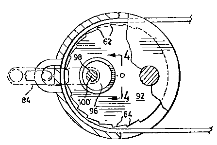
In Figures 2, 3 and 4, manually operable means for pivot-
ing the clamp member 92 between the first and second
clamping positions are provided comprising an eccentric
actuator member 96 pivoted on a crank pln 98 jour~nalled
in the hou~lng walls 3a, 40~ about a ~econd axi~ ~ whlch
ls oee~e~ erom ~he clamp memher axis and parallel th~re-
to. ~'he clamp memb~r ~2 i provided with a corre~poncling
bore ~ having an internal wall 82 which i9 adapted to be
engaged by the eccentric actuator member for pivoting the
clamp member from side to side between the first and
second clamping positions. The crank pin 98 extends
outwardly through one wall of the housing, and an exter-
nal manually operable lever 84 is firmly attached to the
crankpin, for pivoting the actuator member.
If desired, the first safety line can be 1 3/4 inches
wide resin treated latex nylon safety strapping material
having a thickness of 5/32 inch, as shown Eor example in
Figure 4. The edge 86 of the clamp member 92 is formed
to conform with the cross-sectional configuration of the
strapping material. In this case, gripping surface 86
(Figure 4) has a rectilinear edge, as viewed in cross-
section.
7~0
To operate the pole climbing aid, it is of course neces-
sary initially to insert the first safety line member
into the clamp. Normally this would be done during
manufacture. The climber will attach the asse~bled clamp
to a first D-riny 14 on the body belt 10 worn about the
waist, extend one end portion 22 of the first safety line
held in the clamp across his waist, and attach it to the
second D-ring 16 by means of the snap-hook 2~, thus
forming a bight 29 extending between the first and second
D-rings. By pushing inwardly toward the housing on the
appropriate end of the first safety line, the length o~
the bight can be adjusted as needed. The line is then
clamped to prevent its further movement, either by
manually shifting the clamp member into the clamping
position using the lever 84, if available, or by pulling
on the ~lrst end portio~ ~2 oE the llne ~0, to pivot the
clamp lnto the ~perative positt~n
The cllmber can ~a3ily release th~ clamp manually in
order to readjust the bight 29, simply by releasing any
tension on the line 20 and then pushing inwardly the
appropriate end portion of the line to urge the clamp
member into the neutral position. Further inward pushing
on the same end portion of the line will permit the line
to be moved through the opening, and the clamp can
subsequently be re-locked once the line has been suitably
adjusted.
This self-locking action of the clamp member in response
to traction on the line is an important safety feature of
the invention. So long as traction on the bight con-
tinues, the clamp member cannot be easily released. If,however, the clamp member is placed in the neutral
position and traction is exerted on the bight, i.e. by
pulling it, the clamp member is caused to move into the
clamping position, restraining further movement on the
line.
~6~6~3
The climber will snap one end of the second safety line
member 30 onto the bight 29, and extend the free end of
the second line member 30 several times about the pole to
be climbed, preferably in the form of a "Kellam's Grip"
31 as is illustrated in Figure 1. This may be done by
coiling the line helically about the pole, at first
upwardly several times and then downwardly several times,
the downward circuits overlapping the upward circuits in
two positions as shown. The free end of the second
safety line is then attached to the bight 29 formed by
the first safety line
An alternative means of attaching the "Kellam's Grip" to
the bight 29 is shown in Figure 1A. In this a line grip-
ping device 72 comprises first and second slip collars 74
and 76 at lts ends and an elongated resilient link 78
~oining ~he slip collars. 'rhe link 7a i9 nO~mAlly
r~ctilinea~ but is resllien~ly Elexlble ~o p~rmit th~
line ~0 to b~ th~c1cd ~hrough the sllp aollars. One end
of the line 30 is attached to the bight 29 by means of
one snap-hook 32, while the other end of the line is
threaded through the attaching ring 80 of the snap-hook
32 and through the slip collars 74 and 76, the slip
collars being positioned on opposite sides of the ring
80. It will be understood that the other snap-hook 34
will need to be removed prior to threading the line 30
into the slip collars and attaching ring. The slip
collars are adapted to be pivoted to engage the line 30
on opposite sldes o~ the ring 80. One of the slip
collars is adapted to abut against the ring ln response
to tension in the line to bias the other slip collar into
tighter engagement with the line. The use of the line
gripping device 72 or another suitable line gripping
device enables the "Kellam's Grip" to be self-supportedly
positioned on the pole, and to retain its grip on the
pole even when tension on the line 30 is lessened or
released.
- g _