Note: Descriptions are shown in the official language in which they were submitted.
126~i85~
FN 40260 CAN7A
BONDED ADSOR8ENT STRUCTURES AND RESPIRATORS INCORPORATING SAME
BACKGROUND OF THE INVENTION
The present invention relates to bonded adsorbent
5structures particularly suited for filtration of gases and vapors
and respirators incorporating such bonded adsorbent structures as
the active gas and vapor flltration elements. The bonded adsorbent
structures are of substantially uniform thickness and density
throughout resulting in uniformity of air flow therethrough.
lOAdsorbent structures have long been used for the
filtration of fluids and some forms have been specifically
developed for use in gas and vapor respirators. These known
structures are generally classified according to the manner in
which the adsorbent material is supported and include (a) packed
15beds, (b) loaded nonwovens, (c) loaded foams and (d) bonded
adsorbents.
Of these known adsorbent structures, only the packed
beds have been developed sufficiently to meet the str1ngent
filtration and air flow requirements necessary for gas and vapor
20respirator approval from the pertinent regulatory agency. In such
; ~packed beds, adsorbent particles are constrained in a container by
compressive forces imposed on and transmitted through the particle
bed by rigid grids and screens which cover the inlet and outlet
areas. Virtually all such packed bed filters are cylindrical, have
25constant thickness or bed depth and have a planar inlet and
outlet. The adsorbent particles are filled layerwise by pouring
through screens. The screens scatter the particles as they fall
resulting in a level filled bed packed to substantially maximum
density per unit volume. The compressive forces applied by the
30constraining grids and screens restrain particle movement to
thereby minimize flow channeling within the packed bed.
Although gas and vapor respirators with packed bed
filter elements satisfy the necessary performance parameters, the
very nature of the packed beds has imposed severe constraints on
~ ~ 35
.. - ' ' '.
,
1 ~6 6 8 5'~
overall respirator design. Thus, their cylindrical geometry
dictates incorporating the filter element as an appendage
(external cartridge) on the respirator which results in some
interference with vision and an increase in the number of
respirator parts. Another problem encountered with packed beds for
use in a volume sensitive product such as a respirator is that the
retaining grids and screens themselves add to the total volume and
consequently add bulk to the filter element. A still further
problem is experienced when a packed bed respirator is combined in
series with a particulate filter for use in environments
containing particulates as well as vapor hazards such as in paint
spray applications. In this situation, the retaining grids and
screens create nonuniform airflow pathways within the particulate
filter resulting in reduced utilization of the filter media and
increased pressure drop therethrough.
Adsorbent loaded nonwoven structures such as described
in U.S. Patent 3,971,373 contain adsorbent particles in the inter-
stices between the fibers -forming the nonwoven web. Such
structures permit the manufacture of conformable shaped
respirators thus overcoming the design restrictions imposed by the
geometry of packed bed adsorbent structures. However, the high
density of adsorbent particles achieved in the packed bed
structures is lost in the adsorbent loaded nonwoven structures
because the fibers themselves act as spacers between the adsorbent
particles. This low adsorbent density makes it difficult, if not
impossible, to achieve the filtration requirements for approvable
respirators since it is difficult to pack sufficient adsorbent
particles into the small available volume of a respirator. Another
form of adsorbent loaded nonwoven structure is adsorbent paper
where adsorbent particles are ;ncorporated in the spaces between
the paper fibers; these adsorbent papers are also lower density
structures.
Open celled loaded foam structures containing adsorbent
particles dispersed within and bonded in the foam structure have
been developed for various uses, e.g., as an adsorbent composite
for evaporative emission control for automobiles (U.S. Patent
3,813,347), a carbon impregnated ~oam particularly suited for
lZ6685~
protective clothing aga;nst noxious chemicals in liquid or vapor
form (U.S. Patent 4,046,939) and an impregnated foam sheet
deodorizer insole (U.S. Patent Re. 29,501). Most of the loaded
foam structures also suffer the limited density disadvantage of
the loaded nonwoven structures thus limiting their use in
respirators.
Bonded adsorbent structures have been utilized as liquid
filters for many years. While these structures have had the
potential for the high adsorbent densities needed for respirators
and other critical air filter uses, that potential has not been
recognized and exploited.
The known bonded adsorbent structures can be subdivided
into two major classifications, viz., those in which the
contaminant must first pass through a polymeric binder coating
surrounding the adsorbent particle before it is adsorbed by the
particle and those where the contaminant encounters the adsorbent
particle through uncoated areas on the adsorbent surface.
Examples of bonded adsorbent structures where the
adsorbent particles are coated by a polymeric binder are U.S.
Patent 3,091,550 directed to semi-rigid materials having a bonded
adsorbent coating thereon and U.S. Patent 4,386,947 directed to
apparatus for adsorbing fuel vapor in an internal combustion
engine wherein the vapor adsorbent is preferably formed from
layers of molded monolithic honeycombed activated carbon bodies.
The second type of bonded adsorbent structures, where
portions of the adsorbent particle surface are exposed, is
exemplified by U.S. Patents 3,217,715; 3,353,544; 3,354,886;
3,375,933; 3,474,600; 3,544,507; 3,645,072; 3,721,072; 3,919,369;
4,061,807 and 3,538,020. Of the myriad of intended applications
for these bonded adsorbent structures, only U.S. Patent 3,544,507
suggests, in passing, that the agglomerated carbon particles
produced could be used as gas mask filters, presumably as a packed
bed cartridge. U.S. Patent 3,538,020 is directed to bonded
adsorbent bodies comprised of fluid treating aggregate particles
such as ion exchange resins, activated charcoal, manganese
greensand, sawdust and like materials bound together in closely
packed abutting relationship in a matrix of a polymeric material
.126685f~
such as polyurethane, the aggregate particles being spaced
essentially as they would be in a packed bed. It is, however,
expected that a significant portion of the interstitial volume
will be occupied by the binder matrix with a resultant increase in
pressure drop in the bonded structures. Since no respirator use is
suggested in the patent, any possible respirator use to be
inferred for such structures would be as substitutes for packed
bed filter cartridges. While this patent and a number of the above
noted patents state that the bonded adsorbent structures could be
molded into any desired shape, most of the shapes exemplified are
flat or cylindrical bodies. U.S. Patent 3,721,07? does disclose a
differently shaped filter comprising activated carbon granules
bonded together into a monolithic extended surface shape in the
form of a wave, the filter being particularly useful in air
handling systems according to the patentee.
The fact remains that none of the patents specifically
addresses respirator applications nor provides any basis for
concluding that such bonded adsorbent structures could be used as
the filter elements in respirators where high dynamic capacity and
high efficiency contaminant removal with low pressure drops and
uniform air flow are essential characteristics.
Summary of the Invention
The present invention 1ies in porous bonded adsorbent
structures particularly suited for filtration of gases and vapors
and respirators incorporating such structures as the active gas
and vapor filtration elements. These respirators provide
respiratory protection for workers in environments containing
hazardous gases and vapors. The bonded adsorbent structures are
made by combining adsorbent granules and polymeric binder
particles by controlled compaction into porous unitary structures
of uniform and controlled density and air permeability throughout
resulting in uniform low pressure drop and air flow across the
entire structure.
'
1266~5'~
-4a- 60557-3066
~ore specifically, the invention provides a shaped
porous filtering structure of spaced individual adsorbent granules
bonded to one another by adherent binder particles, said structure
being suitable for use as the filtration media in a respirator for
filtration of gases and vapors, said structure comprising a
unified, solid, impact-resistant body of substantially uniform
density throughout, said binder particles being of a size
sufficiently smaller than said adsorbent granules for providing a
multiplicity of bonding sites to maintain the integrity of the
structure but also being of sufficiently large size to minimize
coating of the surfaces of said adsorbent granules.
The invention also provides a shaped porous filtering
structure suitable for use as the filtration media in a respirator
for filtration of gases and vapors comprising spaced individual
adsorbent granules bonded to one another into a solid, self-
sustaining, unitary, impact-resistant body by adherent binder
particles, said structure being of substantially uniform density
throughout and being capable of passing 85 lpm of air therethrough
at a pressure drop of not over 40 mm. of water.
The invention will further be described, by way of
example only, with reference to the accompanying drawings.
B
-5-
iZ66854
Brief Descript~on of the Drawings
Figure 1 is a side elevational view of one form of
respirator with molded bonded adsorbent filtration elementsi
Figure 2 is a front elevational view of the respirator
of Figure l;
Figure 3 is a sectional view along the lines 3-3 of
Figure 2;
Figure 4 is an illustrative and greatly enlarged
fragmentary view of the bonded adsorbent body of the present
invention shown before compaction;
Figures 5 through 10 are simplified diagrammatic
sectional views of typical molds immediately before and during
compaction; and
Figure 11 is a diagrammatic sectional view of a test
apparatus for measuring dynamic filtration characteristics of the
bonded adsorbent structures of the present invention.
Detailed Description of the Invention
Referring now more particularly to the drawings, Figures
1 to 3 show a half-mask respirator 10 (covering the nose and mouth
and sealing beneath the chin) with large area bonded adsorbent
filtration elements 20 occupying a major portion of the surface
area of the respirator 10. As will be especially evident from
Figure 3, the bonded adsorbent filtration elements 20 are
incorporated directly into the elastomeric facepiece 11 of
respirator 10. Edge seals 12 between the bonded adsorbent
filtration element 20 and the elastomeric facepiece 11 are made
with a suitable adhesive material such as a hot melt adhesive, hot
melt foam adhesive or a latex adhesive. Adhesives which contain
solvents other than water should be avoided. Respirator 10, as
shown, is otherwise conventional and will not be further described
herein. It is to be understood, of course, that the bonded
.
685'?~
adscrbent structures of the present invention are e~ually useful
in the myriad other respirators which utilize loose packed bed
cartridges, canisters and filter elements. Exemplary of such other
respirators are gas masks and powered air purifying respirators.
The bonded adsorbent structures of the present invention
are produced by first evenly and uniformly mixing and blending
adsorbent granules 21 and binder particles 22 and compacting and
heat bonding the mixture to form porous unitary structures 20 of
controlled uniform density. Useful adsorbent granules can have a
variety of shapes ranging from near spherical to elongated
granules having aspect ratios of length to diameter of from 1 to
20.
An even and uniform distribution of binder particles 22
on the surface of the adsorbent granules 21, as illustrated in
Figure 4, is essential and agglomeration of the binder particles
22 should be avoided for optimum results. The adsorbent granules
and the binder particles can be dry blended, particularly with
smaller binder particles in the range of 200 mesh (U.S. Standard
sieve) and finer, where the attractive forces of the particles to
the granules exceed those forces which tend to detach the
particles from the granules. Where larger binder particles are
used or where the attractive forces are weak, wet mixing is used
to uniformly mix and blend the adsorbent granules and the binder
particles. Microscopic examination of several portions of the
mixed batch, dry or wet, is useful to verify that mixing is
uniform and the binder particles are evenly distributed about the
adsorbent granules and have not significantly agglomerated.
Figure 4 illustrates a condition during the bonding
process where the binder particles 22 have joined the adsorbent
granules 21. The adsorbent granules are spaced apart by the binder
particles and may be compressed to positions of higher density and
lower permeability depending on pressing conditions and degree of
compaction.
8inder materials which have been found useful in the
present invention include thermoplast,c and thermosetting
materials. However, since not all such materials are satisfactory
binders, the following tests were devised to screen candidate
binder materials.
1~66854
Test 1: Polymer Binder Melt Test
Thls test determines the suitab~lity of polymer binder
materials by their softening, melting and flow behavior. Thermo-
setting binders melt at a relatively low temperature, build
viscosity (by crosslinking), become firm while hot and solidify
upon cooling. Thermoplastic binders soften when heated, melt and
lose viscosity with increasing temperatures.
In order to qualify as a useful binder for the present
invention where it is essential to have an open porous structure
with the adsorbent granule surfaces substantially uncovered by
binder material, the binder must wet but not flow out over the
test surface when the binder is heated to its processing
temperature. Binder materia1s which flow out over the test surface
tend to have sharp melting points and/or low melt viscosities.
Useful binder materials are those which melt or soften and resist
flow out over a relatively large temperature range, i.e., they do
not have sharp melting points or they have high melt viscosities.
The wetting and flow-out properties of a polymer binder can be
determined by measuring the contact angle of the binder on a test
surface. During processing, the contact angle for successful
binder materials should be between 45 and 135, preferably
between 75 and 105; These contact angles indicate sufficient
wetting properties without excessive flow out.
For the test surface, a heated stage with a flat surface
is used. The surface energy of the stage surface should match the
surface energy of the adsorbent granule to assure replication of
the wetting properties of the binder material.
Temperature readings are taken when the binder particles
begin to exhibit surface tension smoothening, Tl; when surface
tension effects draw the particle into a smoothly curved droplet
on the heated surface, T2; and when the binder material flows out
as a film on the heated surface, T3. The ideal binder processing
temperature for making bonded adsorbent structures of the present
invention is T2. Useful processing temperature ranges among
polymer binders can be found anywhere between Tl and T3; however,
in general, most polymer binders will be found to have good
bonding characteristics within the desired contact angles at
.1266854
processlng temperatures from T2 to about midway between T2 and T3.
The most useful ranges for different polymer binders can be
empirically determlned by this test and the tests subsequently
described herein, i.e., the pick and coupon tests.
S Test 2: Pick Test
This test is designed to measure bond strength. A
standard adsorbent, viz., Witco activated carbon 950 (Witco
Chemical Corp.) 18 x 40 mesh is used. The test binder material, in
particle form, is heated to its flow-out temperature, T3, and
allowed to spread into a film to a depth about equal to the
diameter of the original binder particles. After the polymer
temperature has been ad~usted to T2, a quantity of standard
adsorbent granules are lightly pressed into the surface of the hot
binder film (using a heat-resistant glove). The test piece is then
cooled to room temperature. A needle or small laboratory spatula
is used to break the adsorbent granules loose from the binder film
by prying beneath the granule edges.
If the granules break away cleanly leaving substantially
no residue in the binder film, failure is interfacial and
insufficient bond strength between the adsorbent and the test
binder material is indicated.
If portions of the adsorbent granules remain in the
binder film, this indicates cohesive failure within the adsorbent
granule and indicates adequate bond strength.
If portions of the binder material are found to adhere
to the adsorbent granules, this indicates cohesive failure of the
binder material and further testing is necessary.
Test 3: Coupon Test
This test is especially useful when cohesive failure of
the binder material occurs, when chemical or other reactions
between the adsorbent granules and binder material detrimental to
good adhesion are suspected, or when a different non-standard
adsorbent is to be used. The coupon is prepared by uniformly
mixing and blending the test ingredients followed by compacting
. ~ .
:
1~;6854
and heat bonding of the mixture into a convenient size for
measuring the desired properties.
Uniform mixtures of adsorbent granules and binder
particles, either dry mixed or stabilized with water, can be
S transformed into bonded adsorbent structures of the present
invention by several means.
Referring to the drawings, Figures 5 and 6 show molds
for producing bonded adsorbent structures 20 of cylindrical
geometry. A measured quantity of mixed adsorbent granules and
binder particles 30 is charged into the cavity of a mold 40 and
heated to its processing temperature T2. Some care must be
exercised in the heating step particularly if the binder material
has a narrow processing temperature range as determined in the
Polymer Binder Melt Test. Upon attainment of the proper processing
temperature, the heated mixture is pressed by piston 41 to a
predetermined thickness provided through adjustable stops 42.
After cooling, the bonded adsorbent structure 20 is removed from
the mold. Alternatively, the structure 20 can be removed while
warm. In this case, care must be exercised to avoid deforming the
structure 20. Teflon or other release agent coated molds have been
found useful in easing removal of structures 20 from the mold.
A more rapid molding process can be accomplished by
separately heating a blended mixture of adsorbent granules and
binder particles and transferring a measured quantity of said
mixture into the mold cavity from a transfer mold tnot shown) and
pressing the mixture to a predetermined thickness with piston 41,
as previously described. In this process, the mold is at room
temperature or at its equilibrium operating temperature or can be
cooled by external means. The time required for removal of the
bonded structure from the mold is considerably shortened.
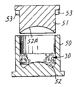
Figures 7 and 8 illustrate molds used for forming bonded
adsorbent structures 20 of compound curved geometry such as shown
in Figures 1 to 3. A measured quantity of a heated mixture of
adsorbent granules and binder particles 30 is transferred into the
cavity of mold 50 from a transfer mold (not shown). Piston 51,
-10-
126685~
having a curved concave face 52A is then advanced into the mold 50
to a depth predetermined by stops 53 to form, in conjunction with
convex face 52, a curved bonded adsorbent structure 20 of
predetermined constant thickness. Adjustments in the density of
the structure 20 formed in this procedure are preferably made by
varying the amount of the mixture 30 charged to tKe mold and not
by adjusting piston travel. Molded structures 20 can be removed
from the mold while still warm but it is important that they be
placed into shape matching nests so as to maintain the correct
curvature until they cool.
In the molding procedures hereinabove described, careful
attention must be paid to the deformation and flow of the heated
mixture of adsorbent granules and binder particles. It is
especlally important to minimize radtal shifts of the heated
mixture during the molding process since uniform air flow
throughout the entire bonded adsorbent structure is critical in
respirator appllcations. Radial shift is the bulk movement of the
mixturs in a radial direction. Radial shift is substantially
avoided in the molds shown in Figures 5 and 6 where the
compression is totally in the axial direction. While there may be
some radial shifting of the heated mixture in the molds shown in
Figures 7 and 8, the shift is minimal and does not deleteriously
affect the uniformity of the molded structure. For extremely
critical curved structures, the heated mixture can be preshaped
before being charged to the mold so as to avoid radial shift.
Molds 60 illustrated in Figures 9 and 10 which involve
gross radial shifts of the mixture 30 must be avoided in the
manufacture of bonded adsorbent structures for use in respirators
and other dynamic applications. The resulting structures have an
extreme density gradient from high in the center to low around the
edges with corresponding variable air flows and pressure drops.
It has long been recognized that approval from the
;~ pertinent government regulatory agency is necessary for a
respirator to be commercially viable. For the United States, the
applicable regulations are contained in Subpart L of Part 11 of
Subchapter B of Chapter 1, Title 30, Code of Federal Regulations,
Federal Register, July 1, 1984 ~hereinafter referred to as 30 CFR
' ''`` ~ '
. ~ .
.
126~854
Part 11, Subpart and Section or USA). Simi1ar regulations have
been issued by other countries. The West German regulations are
widely followed in Western Europe and an applicable German
regulation for respirators is DIN 3181, Part I (hereinafter
referred to as DIN).
A bench test for filter cartridges for chemical
cartridge respirators is set forth in 30 CFR Part 11, Subpart L,
Section 11.162-8 for various gases and vapors. The apparatus
illustrated in Figure 11 was used to test bonded adsorbent
structure 20 of the present invention against carbon tetrachloride
(CC14), an organic vapor. The apparatus 70 comprises a chamber 71
into which the test gas/vapor at a fixed concentration and
flowrate passes through orifice 72, against baffle 73, through the
test bonded adsorbent structure 20 and exits through orifice 74 to
a detector (not shown) and a strip chart recorder (also not
shown). Bonded adsorbent structure 20 is sealed to the test
fixture with conventional modeling clay at junction points 75.
The service life of a filter element is the time of
exposure to a specified constant contaminant flow required for a
specified concentration of the contaminant to be detected in the
effluent stream. Breathing resistance of a filter element is
determined by passing a fixed flowrate of air through the filter
element and measuring the pressure drop in millimeters of H20. The
requirements of the U.S. and West German government standards are
set forth in Table 1 below.
As a further clarification of the relationship between
service life and packed bed or bonded adsorbent filter properties,
the service life is zero at some minimum packed bed or bonded
adsorbent thickness. Increases beyond this minimum thickness
result in corresponding increases in service life. For flat
cylindrical geometry structures where the cross-sectional area is
constant, there is a linear relation between service life and
increase in bed thickness beyond the minimum bed depth. For curved
geometry structures, where the cross-sectional area normal to the
~ 35 flow direction changes as bed depth is added to the minimum bed
; depth, there is a more complex relationship between service life
~ and bed depth or thickness.
:: ~
. ~ - ,
.~ . .
-12-
lZ66854
Table 1
Government Requirements for Dynamic
Adsorption Capacity ~Service Life) and
8reathing Resistance for Gas and Vapor
Fi1ter Elements
Requirements _ ~I
Flowrate (lpm) 64 30
Test gas CC14 CC14
Test gas concentration 1000 1000
(ppm)
Relative humidity (%) 50 75
Temperature (C) 25 20
Breakthrough 5 10
Concentration ~ppm)
Service Life 50 80
(min.)
Inhalation
Breathing
Resistance (mm H20)
30 lpm -- 10.25
9S lpm -- 41
85 lpm 40 --
30 CFR Part 11, Subpart L, Section 11.162-8(b) provides
that where two filter elements are used in parallel, the test
requirements will apply to the filter elements in combination.
Unless otherwise stated bonded adsorbent structures in
two configurations were tested according to one of the regimes set
forth in Table 1. Configuration 1 was a shaped body as shown in
Figures 1 to 3 with a volume of 140 cc, an outer surface area of
90 cm2, an inner surface area of 45 cm2 and a thickness of 1.9 cm.
Configuration 2 was a portion of a spherical shell having an outer
radius of 6.5 cm and an inner radius of 4.6 cm. The shaped body
was obtained by taking that part of the shell subtended by a 2.14
steradian solid angle (as measured from the center of the sphere).
The shaped body had a volume of 126 cc, an outer surface area of
90 cm2, an inner surface area of 45 cm2, and a thickness of
1.9 cm.
.
- 1~6~ S4
The present invention will be better understood by the
following illustrative examples where;n the reported particle
sizes of the polymer binder particles are actual particle size
distributions determined by one of the following two classifi-
cation methods. The first method utilized a Model B RoTap Testing
Sieve Shaker, manufactured by Tyler Industrial Products. The
procedure utilizes a set of six U.S. Standard sieves, arranged in
a stack in descending mesh size order. Sieve sizes used for
classification of polymer binder samples ranged from 35 mesh to
400 mesh. In a specific classification run, a sieve set consisting
of 50, 100, 140, 200, 325 and 400 mesh sieves was used. The 50
mesh sieve was charged with 100 grams of sample polymer binder
particles, placed on the stack in the Sieve Shaker and the Shaker
was run for 10 minutes. Each sieve was weighed to determine the
amount of polymer particles retained on the sieve. The polymer
binder particle size is then expressed as the smallest range of
sieve sizes beginning with the coarsest sieve in which at least
85% by weight of the particles are classified. Thus, a reported
particle size of 100 x 325 mesh means that all particles pass
through the 100 mesh sieve and at least 85% of the polymer
particles have a size within the stated range.
A second method was used for classifying polymer binder
particles which were too fine (smaller than 400 mesh) for
classification by the Sieve Shaker method. In this second method,
the test polymer binder particles were air dispersed onto a
microscope slide and, if necessary further dispersed in oil with a
refractive index of 1.632. Two slides of each sample material were
prepared in the foregoing manner and a total of 10 photo-
micrographs were taken of each sample polymer. From the photo-
micrographs, at least 400 particles were counted, measured and
tabulated into a histogram. The reported particle size distri-
bution is the smallest subdivision of the histogram beginning with
400 mesh and containing at least 85% of the counted particles.
Accordingly, a reported particle size of 625 x S000 mesh (2.5 ~ -
20 ~L ) means that 85% of the particles have diameters within the
stated range.
-14-
685
Example 1
A batch of adsorbent gr~nules and polymer binder
particles was prepared by dry mixing 82 weight percent of Witco
activated carbon 950, 18 x 40 mesh (Witco Chemical Corp.) with 18
weight percent ~nylon-ll powder NCA 1535 ECK, 140 x 400 mesh
~Polymer Corp.). Mixing was accomplished in a one gallon jar by
rotating the jar about its long axis at 80 rpm for 10 minutes.
14.63 grams of this mixture was packed into each of several
aluminum tubes of 4.76 cm internal diameter. After bringing the
tubes and their contents to a temperature of 205C, the tubes were
cooled to room temperature. The structures exhibited good strength
and were tested under carbon tetrachloride challenge as follows.
A 1000 ppm challenge of carbon tetrachloride flowing at
8.0 liters per minute was passed through each of the two bonded
adsorbent structures. The service life of one sample to 5 ppm
breakthrough was 70 minutes and the pressure drop was 7.4 mmH20.
The service life and pressure drop of the other sample was 72
minutes and 6.4 mm H20.
It should be noted that although the test flowrate was
only 12.5 percent of the USA requirement of 64 lpm, the face area
of the sample was also about 12.5 percent of the face areas of a
range of competitive packed bed respirators.
Example 2
A batch of adsorbent granules and polymer binder
particles was prepared by dry mixing, per Example 1, 82 weight
percent of Witco activated carbon 950, 18 x 40 mesh with 18 weight
percent nylon-ll powder NCA 1535 SGJ 100 x 400 mesh ~Polymer
Corp.). Prior to mixing, the nylon powder was passed through a 200
mesh screen to yield a 200 x 400 mesh size distribution.
The mixture was bonded at 205C into a dome shaped
respirator filter element weighing about 130 grams. The dome was
hemispherical and had an outside diameter of 12.06 cm, a wall
thickness of 1.59 cm, and an inside diameter of 8.88 cm. This
hemisphere was sealed to a flat plate havir,g a central orifice and
tested as follows.
7'ra~e~no,rK
-15-
.~26685~
A test cha11enge accord~ng to USA requlrements of 64
llters per minute of 1000 ppm carbon tetrachlor~de in a~r was
passed through the structure flowing from outside to inslde. The
service life was in excess of 60 minutes compared to a test
requirement of 50 minutes. The pressure drop was under 10 mmH20
compared to a test requirement of 40 mm H20 measured at 85 liters
per minute.
Example 3
A mixture of activated carbon granules and polymer
binder particles was prepared according to Example 2. 24.4 grams
of this mixture was placed into each of three glass tubes of
2.50 cm internal diameter and was retained in the tubes by
friction fitted copper screens placed perpendicu~ar to the tube
axis. The tubes were labeled 1, 2, and 3. Into each of three other
tubes (Nos. 4, 5, and 6) was placed 20.0 grams of Witco 950 18 x
40 mesh activated carbon with no binder. The carbon was similarly
reta~ned and was shaken and packed to maximum density.
After heating tubes 1, 2, and 3 in a 210C. isothermal
box, made of 0.32 cm thick copper, for 10 minutes, the pressure
drop characteristics of all six tubes were compared. The contents
of tubes 1, 2, and 3 had a very low pressure drop of only about 10
percent of the others. Tubes 1, 2, and 3 were then reheated and
hot compacted with moderate hand applied pressure. The thus packed
lengths were measured and were found to be essentially equal to
the packed lengths of tubes 4, 5, and 6.
All six tubes were subjected to a challenge of 3000 ppm
carbon tetrachloride in air flowing at 10 liters per minute. The
service life to 1.0 percent (30 ppm) breakthrough was measured.
Results are shown in Table 2.
-16-
i2~;6854
Table 2
Bonded and Unbonded
Adsorbents Exposed to 30 0 ppm CCl~
- Tube No. Packed Pressure Drop Serv;ce Life
Length (cm)(mmH20) (min.)
l 9 274 39.5
2 9 251 40.5
3 9 213 41.0
4 8.9 203 49.0
9.2 178 51.0
6 9.0 206 48.5
Example 4
A dry mix of 80 weight percent 18 x 40 mesh activated
carbon granules (Witco 950) and 20 weight percent 40 x 200 mesh
A 15 polyurethane particles (Quinn P-3429) was prepared. After a few
minutes of mechanical mixlng, it was apparent that the two
materials were not mixing intimately. To achieve the necessary
m1x~ng uniformity, 46 weight percent ~of the mixture) of water was
added. Mechanical mixing was continued for a few minutes resulting
in a very even, intimate mix.
Three increments, labeled A, B and C, of approximately
29 grams each were then placed in metal tubes as described in
Example l. These tubes were placed in a 210C oven until the
material reached 210C as determined by a temperature probe in the
material. The tubes were then taken out of the oven, the contents
pressed uniformly with a cylindrical piston at 5 psi, and then
cooled.
In order to test these bonded structures side by side
with loose packed beds containing the same carbon and carbon
weight, tubes, labeled A', B', C' and D', having an internal
diameter of 4.66 cm were packed by passing 18 x 40 carbon granules
through a 0.5 m long cylinder with coarse screens at the top and
bottom to insure maximum packing density.
The test conditions, based on a 30 lpm flowrate through
70 cm2 face area, were 7.3 lpm flowrate, lO00 ppm CCl4 test gas,
7~ra~e~rk
~'
'
'
~266854
13% RH, and 23C air. The test was run untll 10 ppm was detected
in the effluent. The results are shown in Table 3.
Table 3
Results of dynamic adsorption testing,
5bonded vs. loose packed bed
Polyurethane Loose Packed
Bonded Carbon Bed
A B C A' B' C' D'
Carbon 11.42 12.41 12.44 11.42 11.83 12.5112.43
weight
~grams)
Service 72 66 92 70 82 87 80
Life
(min.)
Average service 76 + 13 80 + 7
life + S.D.
(min.T
Example 5
Molds illustrated in Figures 7 and 8 were used to make
Configuration 1 filter elements 20 shown in Figures 1 to 3. The
two bonded adsorbent filters are mirror images of each other and
were made as described below.
Activated carbon (18 x 40 mesh Witco 950), polyurethane
(40 x 200 mesh Quinn P-3429), and water were mixed per Example 4.
Each filter element contained approximately 77 grams of carbon and
polyurethane, which when put into a 140 cc mold results in a bulk
density of 0.55 g/cc. Increments of the mixture were individually
- weighed, placed in a transfer mold, heated to 195C, extruded from
- the transfer mold into the Configuration 1 mold, and pressed with
approximately 200 psi, as shown in Figure 8. Although the mold was
cold, which allowed for quick cycle times, care was taken when
removing the filter element after pressing. It is recommended that
a nesting surface matching the top or bottom surface of the bonded
~. ~
: " ', ' ~
. ~ ', ' :
-18-
i26685'~
element be provided for the carbon element to rest on until it
cools to below 60C.
The respirator filter elements made were then tested in
pairs (parallel flow) for dynamic adsorption capacity and
breathing resistance per USA and DIN standards. The results of
those tests are shown in Table 4 and it is observed that all
samples passed the respective DIN and USA requirements for service
life and pressure drop.
Table 4
Results of USA and DIN Testing
Bonded element Test Service Pressure
weights-individually Life Drop
and together ~9) (min.) (mm H20)
176.85; 76.37 DIN lZ7 6.0 20.2
153.82 @30 lpm @95 lpm
276.20; 76.37 DIN 127 5.6 19.2
152.57 @30 lpm @95 lpm
376.25; 76.56 DIN 156 5.4 18.6
152.81 @30 lpm @95 lpm
476.95; 77.0 DIN 163 6.0 20.0
153.95 @30 lpm @95 lpm
577.19; 77.37 USA 68 17.2
154.56 @85 lpm
677.61; 77.50 USA 79 20.4
- 155.11 @ 85 1pm
: ~ 777.21; 77.22 USA 78 19.4
154.43 @ 85 lpm
: ~ .
,.
.
, .
-19-
.1~66854
Example 6
A wide range of adsorbent granule sizes were made into
bonded structures according to the process of Example 5. Samples
made included 4 x 10, 8 x 16, 18 x 40, and 30 x 80 mesh granular
activated carbon mixed in a ratio of 80 weight percent carbon to
20 weight percent polyurethane particles. In these specific
samples the ratio between largest carbon granule diameter and
smallest polyurethane particle diameter was approximately 16 and
the ratio between smallest carbon granule diameter and largest
polyurethane particle diameter was approximately 1.2. Many other
size and weight ratios are possible but these samples offered good
strength, service life, and density control.
The samples made were in the spherical shell geometry
(Configuration 2). The bonded elements were tested at 32 lpm, 1000
ppm CC14, 50Z RH air, and 23C until-5 ppm CC14 in the effluent
was detected.
In this example and others to follow, the test
parameters may vary from example to example. To standardize the
data, examples which contain service life and/or pressure drop
data may have columns of service lives and pressure drops
normalized to a standard test. The standard test used for
normalization is two Configuration 2 filter elements tested in
parallel against the USA standard. Thus, the normalized columns
represent data for two filter elements in the USA test.
-20-
126685
Z O O O O U
~ ~ r ~ ~ r
O N ~
C
n
--~ ~ O ~ N -- C---O
o o o r ~ ~
C~ X X X X
~ ~ ~ ~n ID
t~ (D N O W ~ ~
~ Ul O O O ~1 3
O
", _. o~ 5 -s
~ ~ ~ g
O ~D _ ~
~ ~ U:~
-s
o oo ~ P C ~
~ (D X X X X ~ ~D ~ ~
ID '5 O _
g O ~ O ~ ~ ID
. ~ ~ ID ~.
~1 :S ~D
. tD
C
-- w ~ 3 '~ ~0 m ~D
D~ -- W O O '~ ~ -5 ~ ~n
*-~ _
. ~
J g
g ~ ^
. O O~ W ~D
O~ C
O
. ~
~ a~ N ^~ 2
N ~Jl C0 Cl~ -- 3 -5 0
o e _
: .
.' .
.
.
.~.
., .
.
.. . .
:
, .. .
-21 -
lZ~;~85'~
As can be seen from the data in Table 5, structures with
large carbon granules have short service lives and structures with
small carbon granules have excessive pressure drops. For these
reasons, it will be evident that bonded adsorbent structures should
utilize carbon granules having an average size distribution between
the limits of 6 and 50 mesh.
Example 7
.____
Configuration 2 bonded adsorbents were made using the
procedure described in Example 5. All samples contained 80 weight
percent 18 x 40 mesh activated carbon granules (Witco 950) and 20
weight percent polyurethane particles (Quinn P-3429) of varying
sizes.
The samples were tested according to the USA test
conditions, with the results shown in Table 6. It should be noted
that only one Configuration 2 filter element (volume = 126cc) was
tested. This essentlally represents half of a dual element bonded
adsorbent respirator, so the test pressure drops will be higher and
the test service life times lower than the dual element respirator
by roughly a factor of two, as indlcated in the normalized columns.
:
-22-
685'~
OOO OOO OOO ~D~
O O gO O O O g O C ---
XXX XXX XXX
1~ N ~ ~ --S
O O OO O O O O O V 3
OOO OOO OOO ~D
-S
~0 00 0 00 00 0~ 0 . N -S ;~
X X X X X X X X X V~ ~D V Il~
~ ~ ~ ,p ,~ .p ,p ,p ,p O ~,
O O O O O O O O O ~ N _
~ 3 n~ ~
V D O U~
C~ ~ ~ In
V U O
C- C ~.
O C~ O .P ~ 3 --- ID ~D ~D
_. ~D
~ D ~ n
,p ~ ~ ~I _ ~ ~n cn _ --~ Z ~ o
o o a~ o P OD CO O 3 0 Q~ ~c
-- C -S
I +I + I + ~ ~ _- -S ~V
.P N ~n --- CL ~ -S
O ~
I æ u)
-- O--C
+ I+ I+ 3 rD
o
-- _ -- ~ ~ 2
J~ ~00 ~I CO a~ o. ~Jl 3 -~ o
~n v
~ n o ~ --
¦ +I + I _ _.
_
o
-23-
:126685
There are two effects noticed in the table. The first and
most pronounced is that service life drops significantly when the
polymer particle size is less than 400 mesh. A possible explanation
for this effect is the coating of the carbon granule with polymer,
thereby reducing access to the interior of the carbon granule. The
second effect is that pressure drops are lower when the polymer size
is less than 400 mesh. This is not a marked effect as the average
values, plus or minus their standard deviations, nearly over1ap. If
the fine particles combine with the carbon granules in such a way
that the total carbon/polymer external surface area is less than
with the larger particles, lower drag forces will result and hence
lower pressure drops. The service life effect is the more decisive
and the results therefore indicate that polymer mesh size
distribution should be kept between 40 and 400 mesh.
Example 8
Eight polymer resins were subjected to the screening tests
as follows.
Polymers which passed the Polymer Binder Melt and Pick
Tests were made into mixtures of 20 weight percent polymer particles
and 80 weight percent 18 x 40 mesh activated carbon granules (Witco
950). Water was added in the cases where dry mixing did not result
in a uniform mixture. Coupons were then made from the different
mixtures, allowed to cool to room temperature and then examined
qualitatively for bond strength. One of the polymers which showed
good melting behavior and bond strength in the Polymer Binder Melt
Test and the Pick Test failed the Coupon Test. In this instance, it
is believed that a chemical reaction took place during the heating
process which altered the polymer and consequently its bond
strength.
In summary, of the eight polymers screened, two were
eliminated due to failure of the Pick Test, one was eliminated due
to poor melt behavior and one was eliminated in the Coupon Test. The
remaining four polymers were formulated into mixtures and molded as
described in Example 6. These were then tested according to the
conditions set forth in Example 6 with results shown in Table 7
along with the results of the screening tests.
, - ' .
.
-24-
126685'~
--O --C --~~1--W ~ ~ C--~ 3 C~ 2
~J7~ CtD --~ O (~ ~ N C cn 3 ~- S ~- --~ O
-~0 ~~ r ~
~ O ~ n --~ o ~ -~ 3
r -- c --~ Q ~ D O O ~ 3
~D I ~ Q ~ Q ~ Q ~ X ~S) --~ ~ ~U
-- S ~ ~ C ~ I Q
~ c ~ r o ~ I s
3 ~C ~, S ~ n C o W -S
3 ~ ~ 3
~D ~ ---- -- X-~ ~ ~O ;~
_. ~ ~ Tl ~C ~ ~ O --
D 2 C ~ (~
3 ~ ~ 5 ~ n~
C
~D 3 o ~D
Qo
- -- O
~S --.
o ~ 3
~Q ID ~D
5 Vl _ C
c ~ O~ O
~ ~ ~ Vl O Vl ~ O Vl .P U~ --
g ~D O O O O Vl O O O ~ r<C3 ~
~ X X X X X X X X ~ I~ O
a~ ~ ~ O On 1~o ~ g O O Cl~ ~ _
~, 8 o o o o o* o o ~Q ~ _~
~. C * -5 V V
ID ~~ ~ ~ ID
s o o o o o ilF ~ -s ~
-- O ~ ~-
~g ~ ~D
æ vt ~ "' t t t t 3~ ~'
~D
D*
2 ~ ~ vl r ~ ~ I _ ~ ~ u,
3 Vl 11
:~' S ~n
0~ C
3 . --3 -S
~ O
O -- 1~ N -- I I I I --~ Z
O ~ ~ ~ ~ ~ I 1 3 ID 3
3 S ~
a~ o c --
S
~ Q
,
'
-- .
'
,
-25-
6t; 8 5~
Example 9
A batch of 80 weight percent 18 x 40 mesh activated carbon
granules (Witco 950) and 20 weight percent 40 x 200 mesh
polyurethane particles ~Quinn P-3429) was prepared as described in
Example 5. The mold of Figures 7 and 8 was used for preparing
Configuration 2 bonded adsorbent samples that varied in carbon
density from 0.35 g/cc to 0.47 g/cc. This was accomplished by
varying the amount of mixture charged to the mold. These samples
were processed as described in Example 5 and tested according to the
USA standards. Only one Configuration 2 element was tested against
the USA standard so the pressure drops will be higher and the
service life times lower by roughly a factor of two. The results of
these tests with normalized service lives and pressure drops are
shown in Table 8.
-26-
~26685~
N Ul ~0 ~ .P ~P C~ ~) O -- --
~0 ~ O N -- CO O N 0 a~ O S--
OOO OOO OO OOO ~
r ~ ~ ~ r r ~ ~ ~ ~ ~ ~~ ~5
~&~g
J~ ~O ~~ ~ ~ N N-- -- -- ^ ~ -5
o --r ~0~ D ~ 3. _5 o
N ~S N _ ID
t+ I+ I+ I+ ,_ I~
N _~ _.
ID
~ ~ Z
O CO C~ CDN NN C~ r 3 ~ ~ ol
co _ ~n ~ --- ~ ~ cr
~n ~ o ~ _ ~ _
I+ I+ I+ ~+ ~D- -,
' ~D ~
~ 0 00 0~ ~~Jl N N -- -- -- --Ç~ V O
00 J~ N0 0Cr ~ N ~1 Vl .P ~ ~ ;3 i
+ 1+ 1+ 1+ ~3 ~ O
O 3
11~
J~ ~~ ~ N -- -- --V 2
~0 ~J -- ~ Oa~ N-- C~ CO ~1 ~ ~ 3
~ ~ -- C~ N ~n ~
N -- ~ I + _ ~ .
I + I + I + _ ID
O Cl.
: :
. ', ' ` ', .
'
: ' ' ~' ' ' ' ~ ' .
.
: ' ' , ,
-27-
1~6~;85 ~
Examinatlon of Table 8 will show that a wide range of
carbon densities are possible while still offering reasonable
filtration performance. This is, of course, not true for loose
packed beds which are always packed or loaded to a max;mum density
for a given adsorbent. The apparent density (as determi~ed by
ASTMD-2854-70) of the carbon used in this example is 0.44 g/cc;
thus, it is seen that bonded adsorbents offer carbon densities well
below and above the apparent density of the carbon when loose
packed according to ASTMD-2854-70. Aside from offering great
latitude in the manufacture of bonded adsorbent filters, density
control offers more versatility in filter design.
While the low and the high density values in Table 8 do
not literally meet the USA standards for a half mask respirator, it
should be possible, as the values are close to those required, to
make geometric adjustments to the bonded element to bring these
values within the USA requirements.
Example lO
To best utilize the adsorption capacity of activated
Z carbons, it is very desirable to have unlform air flow across the
entire cross-sectional face of the filter. If the flow Ms not
uniform across the surface normal to the flow direction, then that
area of the surface which has a higher flow velocity ~lower
pressure drop) will begin to break through first. A great deal of
effort has been put into eliminating this problem for loose packed
beds resulting in specific ways to pack the beds to maximum packing
density.
In this example, bonded adsorbents are compared with
convent10nal commercially available loose packed beds for
un~formity of airflow.
The loose packed bed was a 3M Easi Air #7251 cannister
with a 7.3 cm diameter and a height of 2.4 cm. Carbon from one of
the Easi Air cannisters was removed and used to make a bonded
adsorbent filter under the process conditions of Example 4. The
bonded filter was processed in a mold as shown in Figures 5 and 6,
the final dimensions being a height of 2.6 cm and a diameter of
7.3 cm.
-2~-
1266~5
A hot wire anemometer, T.S.I. Model No. 1650 (Thermo
Systems Inc.) was used to test the uniform1ty of flow across the
surface. The circular filters were placed between two 10 cm long
cylinders with 7.3 cm diameters. The edges were sealed with
modeling clay and eight equally spaced holes were bored around the
perimeter just above the surface of the filter to allow access for
the hot wire anemometer probe. The cylinders were used to provide a
plenum for the effluent and to reduce edge effects on the influent
side of the filter. An airflow of 85 lpm was passed through the
filters, during which time the velocity was measured at nine
positions, eight equally spaced around the perimeter (0.7 cm from
the edge) and one at the center of each filter. As a test standard
a 0.64 cm thick, 7.3 cm diameter piece of 3M Grade 175 Tegraglass
was used. Tegraglass is a very uniform porous body comprised of
uniform glass spheres bonded together in a fashion very similar to
hexagonal close packed bodies.
The results of the velocity measurements for each of the
test samples were as follows:
a) Tegraglass - 66 cm/s at each of the nine positions.
b) Bonded adsorbent of the present invention - 66 cm/s
at 0, 45, 90, 135, 225 positions; 61 cm/s at center and 180
positions and 71 cm/s at the 315 position.
c) Loose packed bed - 61 cm/s at 0, 45, 90, 180, 225
and 315 positions; 66 cm/s at 135 and 270 positions and 56 cm/s
at the center position.
It will be observed that the uniformity of air flow
across the entire face of the bonded adsorbent structure of the
present invention is substantially uniform and is at least
equivalent to the air flow characteristics of the loose packed bed
structure presently used in respirators.
Example 11
Six batches of Witco 18 x 40 mesh 950 carbon and 40 x 200
mesh Quinn P-3429 polyurethane were mixed per Example 4 with carbon
amounts ranging from 60 to 85 weight percent. Three samples from
-29-
1266~35'~
each of the six batches were made using the spher~cal shell mold
(Configuration 2) and then tested per the USA standards. Only one
Configuration 2 element was tested so the pressure drops will be
higher and the service life tlmes lower by roughly a factor of two.
The results of these tests with normalized service lives and
pressure drops are shown in Table 9.
-30-
1266854
ooo oo ooo ooo ooo ooo --cC
o
r ~ ~~ ~ ~ ~ ~ r~ v Ov
Ooo ~n ooo ~ n ooo~n~n~ ~oo _
_~ _ U
~n co u~ o a~ o o ~ ~ ~- 3 D 'D
N ~ . t~
0 0 ~ -- ~ O
I +I + I + I + ~ .
~ _ . ~
(D ~
~ ~ W~ ~n ~ ~ r ~ --~ z ~D
O~ CO O N~n .P ~ ~ P ~ CO O O ~ ~ 0 3 tD O ~n
~ ~ r ~ , ' ' 3 c ~
~ ~ V
¦ + I + I + I + I + I ID ~- J --
C~ DVl cn ~ ~ ~ ~ ~11~ 7 N -- ^ ~ v O
oo 1~co ao o -- o ~-- co 1~ ~N -- -- 0 3 'S
-- ~ ~0 0~ 1~ 0 0--C I'D
+ 1+ 1+ 1+ 1+ 1+ ~3-~ -3S
-- N -- -- 5 ~
~ ID
~O~.p ~______--__ _---- --VZ
o ~ o r ~ -- ~ ~ 3 D o
-- -- O C --
I + I +~ + ~ + ~ +
w r---- -- -- o ~
-31 -
i~66854
The results show that polymer contents of 30 percent or
more are deleterious to filter service life or pressure drop. The
high pressure drops and reduced service lives at these percent
levels are generally unacceptable in half mask respirators, but may
be useful where strength is the most critical design parameter such
as in powered air purifying respirators.
Example 12
Ten polymers were mixed with Witco 950 18 x 40 mesh
activated carbon in a ratio of 80 weight percent carbon to 20
weight percent polymer. Water was added to those mixtures that did
not mechanically mix in the dry state. From these mixtures
cylindrical bonded adsorbent bodies (diameter = 9.1 cm, height =
1.9 cm) were made using the mold illustrated in Figures 5 and 6.
A typical concern with presently available packed bed
cartridge respirators is that rough usage and handling conditions
may lead to channeling of flow in the loose packed bed. Since the
bonded adsorbent structure of the present invention is a unitary
structure, channeling is not a problem. However, cracking or
breaking of the bonded filter element under rough handling or usage
conditions may be encountered. For this reason, the bonded
adsorbent bodies were tested for impact resistance in the following
manner.
The cylindrical bonded adsorbent bodies were dropped from
two heights onto a concrete floor. The surface normal to the
cylinder axis was held so that it was parallel to the floor and
then released from rest. Those bonded structures which did not
break in the drop test were tested for dynamic adsorption capacity
according to the USA standards. The dynamic adsorption test was run
for 10 minutes; if the effluent airstream did not reach break-
through concentration ti.e., 5 ppm CC14), it was considered
undamaged by the impact test. The results of these tests are given
in Tables 10 and 11. Table 10 gives the results of the impact test
for a height of 2.5 m and Table 11 for a height of 3 m; separate
structures were used for each test.
-32-
126~i85'~
,~ ~
*
. ~ .
C rTI W I W C --C ^ ~ ~ 1~ ,0 ~ ~
W V I~ C C g
3 0~ ~c o 3 3 ~ ~ --3 3
~ '5 ~ g ~ ~D oO ~ ~ ~ I ~ ~ ~ ~ r ~ (D
o ~ c ~ ~~ a~ ~ c ~ ~ --
~ ~D ~ 9 ~ ~ ~ I --o o ~n r I O
--~ ~ V N~, 3 ~ 5 V- ~ --- . ' -- :i;~--.
O ~ ~ -- ---- 2 Z O ~ ^
~1 0 ~ o Y -rl V -~1 g g ~ -- O
Z ~C ~ -- Z ~ C l~ _
8 ~ o ~n, ~ ~ v N W ~ ~
V ID D0- ^ ~D ~ V 5 (D
O C-- O -- ~D
~D -- V -- O
W W N -- -- -- .p W N W 10 I'D ID
cn J~ _ -- W O N J~ O CO ~
COO -- -- ~ ~O O O 0~ 5 _
^ 3C ~ O
g ~n~n g ~n o ~ O O C ~ ~
OO O O O O O O O W :r~5 N
XX XX X XXXXX ~ ~
N Ul W ~ ~ 3 _
~n rN O O ~ W N N W 1~1 ~ a~ ID
O OO O O O N O O ~ ~ 1~
o oo o o o ~n o o ~n D _
_~ ~ ~t
rl N -- ~n ~ -- O ~ ~
- 2
3c~ 3 ~, w w 3 ~, w ID
", ~ C
O OO O O ~ I O O ~ ~ ~ 3
3 ~ t
, ~ ' ~ O
W N N W N I I N N I ~ CO
N N W-- ~ ~ ~ .r . N (~
CO O ~ 0 0~ C
V
.~ , .,
~,.:- ; '
"' ~ . -
~' , -
-33-
12f~685
crTI ~n I W C --C ^ ~ ~
a~ o ~ O O C c g o o
3 O' ~ o~ ~i 3 ' ' ~ ~3
7 ~ ~D ~, ~, ~ ~ ~
Q tD o n. ~ Q ~
C ~ D C --g g J~ W ~ g
~ NS O ~- ~ C ~ -S ~ ~1 1~ ITI -S
-- ---- 2 2 0 ~ --
~ o X, O ~ 71 ~ ~ g g ~ O
z -- c ~ -- z ~ c ~ --
o ~ ID ~- -S ,~^~ ~ W V~ ~I
,,~,,,~, _ 5
^ ~ 5
-S~ O C~ O -- ~D
~-- O
Q~ _
--
;~
U~ O ~Jl N cn ~0 O 1~ 5 C
_
C ~ O O
O ~ Jl O ~Jl O ~ l ~ O u~ --
O O O O O O O O O 0 ~5<~
X X X X X X X X X X ~ 3 _i
1~ ~1 ~1 ~ ~.1 a~ _
~0 0 0 0 0 Og ~ 0 O ~ . ~ ~5 _
~ _.
C~ ~
Q ~: 1~
~ o ~. D
llQ~
w w 3 w ~, w w ~ c~ w .D
O ~ O I I O O I ~ ~ 3
3, _.
~ O
-
--~D 'V
o~ o ~ o--C
_~
~0
-34-
i26685~
Of the possible results of the test, i.e., break~ng into
discrete parts, visible cracking and no visible damage, only the
first and third results were observed as indicated in the results
column of the Tables. The impact resistance data provide a very
useful parameter for proper polymer selection. It has been
determined that structures which passed the 2.5 m impact test were
satisfactory structures for respirator uses.
Example 13
The lacquer and enamel mist test aerosols described in
30 CFR Part 11, Subpart L, Sections 11.162-4, 5, and 6 were
prepared and passed through bonded adsorbent filters fitted with
paint spray prefilters as described below. The lacquer used was a
50/50 volume mixture of Dayco brushing lacquer No. 5004 and Dayco
lacquer thinner, both available from James B. Day and Co. The
enamel used was 50 volume parts of gum spirits turpentine from
AMSCO Division, Union Oil Co. of California, and 50 volume parts
of "Quick Dry" enamel No. 54-352 from PPG Industries, Inc.,
Coatings and Resins Divisions.
The bonded adsorbent elements were each spherical
segments of 0.84 cm thickness, outside radius 6.50 cm, inside
radius 5.66 cm; the portion of the shell used being subtended by a
2.14 steradian solid angle. The composition of the bonded
adsorbent structures was prepared according to Example 4. Across
the outer surface (90 cm2) of each of the two elements used in the
enamel test was fitted a paint spray prefilter of relatively
coarse nonwoven felt material. The paint spray prefilter used for
the lacquer tests was a portion of a 3M No. 8718 prefilter web
sufficient to cover the 90 cm2 surface.
The elements used were similar in size (except thinner
in thickness) to elements used for left or right respirator
elements. Since only one element was used the 32 lpm flow require-
ment was reduced to 16 lpm. Both tests were run for the required 2
hours and 36 minutes and the bonded adsorbent elements were then
examined visually and subjected to the shock test of Example 12
and were found to have suffered no apparent deterioration in
physical properties. Air flow through the paint spray prefilter
;: .
'
"
.
.
: :
.~ ' .
-35-
12668~4
web was uniform as evidenced by the smooth deposition of paint
spray particles over the entire prefilter surface.
Example 14
It has been noted earlier that the service life of a
s filter element is the time of exposure to a specified constant
contaminant flow required for a specified concentration of the
contaminant to be detected in the effluent stream. The thickness
or depth of a filter element of a given cross-sectional area is,
of course, the major determinant of the volume of the filter
element. At a certain bed depth, a respirator filter element will
have a service life of zero minutes where there is immediate
detection of the contaminant. This is the minimum bed depth for a
filter element. Increases in thickness or bed depth beyond this
minimum thickness will result in corresponding increases in volume
of the filter element and, therefore, service life.
The minimum bed depth for a bonded adsorbent structure
of the present invention was determined using a standard 100 ppm
iso-amyl acetate test atmosphere. Iso-amyl acetate was selected
because it .is known to have dynamic filtration characteristics
similar to carbon tetrachloride and because low concentrations
have a distinct banana-like odor. Bonded adsorbent structures
having a diameter of 7.31 cm were fitted to the right side of a 3M
Easi-Air respirator No. 7300. The left side was fitted with a
standard packed bed respirator cartridge (3M cartridge No. 7251).
With the right side blocked off, the test subjects each verified a
non-leaking face seal. Then with the left side blocked off, the
subjects were able to breathe through the bonded adsorbent
structures alone. Results for cylindrical bonded adsorbent
structures made according to the composition and processing
conditions of Example 5 are presented in Table 12.
-36-
1266~354
Table 12
Minimum Bed Depth Determinations
At Human Respiration Flow Rates
BONDED ADSORBENT DESCRIPTION ODOR DETECTION
No. Wei ht Thickness Normal Heavy
~ ) Scm) Breathing sreathing
1 14.58 0.66 None Slight
2 14.50 0.66 None Slight
3 21.74 0.98 None None
4 21.56 0.98 None None
It will be observed that the 0.66 cm filters had a
thickness at about the minimum bed depth while the thicker, 0.98
cm, filters had a thickness exceeding the minimum bed depth for a
range of breathing flow rates. Effective filter elements of 7.31
cm diameter must, therefore, have a thickness greater than 0.66
mm.
Example 15
This example illustrates the relationship between
density and permeability for bonded adsorbents and establishes
permeability criteria for application in respirator design.
Eighteen bonded adsorbent structures were made according
to the process outlined in Example 4. A mold as shown in Figures 5
and 6 was used to make cylindrical bonded adsorbent elements of
9.2 cm diameter and 1.9 cm height. Six sets of three elements per
set were made by varying the weight of material charged to the
mold. The edges were sealed and a flow of 42.5 lpm was passed
through individual elements in an axial direction. Pressure drop
measurements were used to calculate the permeability of the bonded
adsorbent materials using Darcy's law and the results are given in
Table 13.
, -, - -, . . .
. ~ ,. ' , -
:: : -
. . - ~ : -
- . -
-37-
1266854
Table 13
Density of Bonded Adsorbent Structures
weight bulk carbon Pressure Drop* Perme~bility
(grams) density density42.5 lpm x 12
(g/cc) (g/cc)(mm H20) (cm )
53.84 0.43 0.34 5.4 7.0
53.44 0.42 0.34 5.6 6.7
55.00 0.44 0.35 5.8 6.5
59.34 0.47 0.38 8.4 4.5
59.20 0.47 0.38 7.8 4.8
58.76 0.47 0.38 9.2 4.1
62.98 0.50 0.40 15.2 2.5
! 15 62.80 0.50 0.40 11.8 3.2
62.61 0.50 0.40 13.2 2.9
66.76 0.53 0.42 17.0 2.2
66.59 0.53 0.42 17.6 2.1
66.42 0.53 0.42 15.6 2.4
70.70 0.56 0.45 34.8 1.1
70.36 0.56 0.45 25.2 1.5
70.62 0.56 0.45 29.2 1.3
74.26 0.59 0.47 42.6 0.9
74.22 0.59 0.47 29.8 1.3
; 25 75.26 0.60 0.48 62 0.7
*Pressure drop was not normalized since test
was run with one element at 42.5 lpm
Based on a half mask respirator and using the USA
cr1teria of a 40 mm H20 inhalation breathing resistance at 85 lpm,
.
.
.
~6685 ~
it is clear that two of the cyl~ndr~cal bonded adsorbent
structures of this example with 42.5 lpm flowing through each
should have a permeability limit of about 1.0 x 10 6 cm2 or about
100 Darcys. (1 Darcy = 9.87 x 10 9 cm2).
Configuration 1 bonded adsorbent structures were also
made matching the highest carbon density of Table 8 and were
tested at 42.5 lpm. The pressure drop information indicated a
permeabil;ty limit of about 1.0 x 10 6 cm2. The similar
permeability limits which resulted for Configuration 1 structures
compared to the cylindrical structures of this example indicate
approximately equal flow resistance for the two structures in
spite of their dissimilar geometry.
Example 16
To demonstrate the feasibility of using bonded adsorbent
filters in powered air purifiers, 400 grams of 8 x 16 mesh
activated carbon granules (Witco 965) and 100 g`rams of 40 x 200
mesh polyurethane particles (Quinn P-3429) were mixed with 250
grams of water per Example 4. The mixture was then charged to a
rectangular prism mold, heated to 195C., and then pressed into a
final shape having dimensions of 17 cm x 17 cm x 3 cm. The
resulting bonded adsorben~ filter was then tested by replacing the
loose packed bed filter element in a NIOSH approved commercially
available powered air purifier ~Powered Air Purifier, Model
W-2801, 3M Company) with the bonded adsorbent rectangular filter.
A bench test for canisters and cartridges for powered
air-purifying respirators is set forth in 30 CFR Part 11, Subpart
M, Section 11.183-7. The bench test specifies carbon tetrachloride
at a concentration of 1000 ppm, a flow rate of 170 lpm, relative
humtdity of 50 + 5% at room temperature (25 + 5C.). Minimum
service life~ is 50 minutes, determined when the effluent
concentration reaches 5 ppm. Maximum allowable resistance
(pressure drop) of the powered air-purifying respirator at 85 lpm
is 70 mm of water, measured after service life testing (30 CFR
Part 11, Subpart M, Section 11.183-1).
The results of these tests are shown in Table 14.
' ' ' ' ' ' -
-39-
~2~;~;8 5
Table 14
Results of service life and pressure drop tests
Filter Service Life* Pressure Drop & 85 lpm
~min.) (mm H20
Bonded 80 3
adsorbent
Loose packed 118 8
bed filter
~ There appears to be some confusion in the requirement for minimum
service life. As originally published in March 1972, a service life
of 50 minutes was required by the applicable regulations. However, as
published in July 1984, no minimum service life is designated.
Currently available information is that NIOSH requires a minimum
service life of 50 minutes for approval of canisters and cartridges
for powered air-purifying respirators.
Examination of Table 14 will show that the bonded adsorbent
structure of the present invention easily meets the service life and
pressure drop requirements of the applicable regulations and compares
favorably with the loose packed bed filter element of the NIOSH
approved commercial powered air-purifying respirators. Also, as
earlier noted, the service life can be controlled by varying the
quantity and/or density of the carbon granules in the bonded
adsorbent structure.