Language selection

Search

Patent 1267135 Summary

Third-party information liability

Some of the information on this Web page has been provided by external sources. The Government of Canada is not responsible for the accuracy, reliability or currency of the information supplied by external sources. Users wishing to rely upon this information should consult directly with the source of the information. Content provided by external sources is not subject to official languages, privacy and accessibility requirements.

Claims and Abstract availability

Any discrepancies in the text and image of the Claims and Abstract are due to differing posting times. Text of the Claims and Abstract are posted:

  • At the time the application is open to public inspection;
  • At the time of issue of the patent (grant).
(12) Patent: (11) CA 1267135
(21) Application Number: 1267135
(54) English Title: METHOD OF LAYING OPTICAL CABLE IN AERIAL LINE
(54) French Title: METHODE D'AJOUT D'UN CABLE A FIBRES OPTIQUES A UNE LIGNE AERIENNE
Status: Expired and beyond the Period of Reversal
Bibliographic Data
(51) International Patent Classification (IPC):
  • B65H 59/00 (2006.01)
  • G02B 6/44 (2006.01)
  • G02B 6/48 (2006.01)
  • H02G 1/04 (2006.01)
(72) Inventors :
  • IKEYA, TAKAO (Japan)
  • KATSUOKA, NORIO (Japan)
(73) Owners :
  • THE FURUKAWA ELECTRIC CO., LTD.
(71) Applicants :
  • THE FURUKAWA ELECTRIC CO., LTD. (Japan)
(74) Agent: SMART & BIGGAR LP
(74) Associate agent:
(45) Issued: 1990-03-27
(22) Filed Date: 1986-08-22
Availability of licence: N/A
Dedicated to the Public: N/A
(25) Language of filing: English

Patent Cooperation Treaty (PCT): No

(30) Application Priority Data:
Application No. Country/Territory Date
60-206689 (Japan) 1985-09-20

Abstracts

English Abstract


METHOD OF LAYING OPTICAL CABLE IN AERIAL LINE
ABSTRACT OF THE DISCLOSURE
A method of laying an optical cable in an aerial line which
comprises the steps of winding the optical cable measured in a
necessary length between laying zones on a reel, mounting optical
connectors at both ends of the reel, laying the optical cable by
winding at the aerial line by mounting the reel on a winding machine
moving on the aerial line already installed, disposing the optical
connectors on the supports at both ends of the laying zone,
similarly laying at the adjacent zones of the laying zone, and
connecting the optical cables of the adjacent zones on the support.
Thus, since the optical cables of the adjacent zones can be con-
nected on the support, the connecting work at the laying site can be
extremely simplified. Thus, this method can very simply connect at
the laying site by connecting the optical cables of the adjacent
zones on the support.


Claims

Note: Claims are shown in the official language in which they were submitted.

- 5 -
THE EMBODIMENTS OF THE INVENTION IN WHICH AN EXCLUSIVE
PROPERTY OR PRIVILEGE IS CLAIMED ARE DEFINED AS FOLLOWS :
1. A method of laying an optical cable in an aerial
line, comprising the steps of:
winding the optical cable measured in a necessary
length between laying zones on a reel,
mounting optical connectors at both ends of the reel,
laying the optical cable by winding at the aerial
line by mounting the reel on a winding machine moving on the
aerial line already installed,
disposing the optical connectors on the supports at
both ends of the laying zone,
similarly laying at the adjacent zones of the laying
zone, and connecting the optical cables of the adjacent zones
on the support.
2. The method according to claim 1, wherein said optical
cables of the adjacent zone is connected merely by connecting
the optical connectors on the steel towers in which the ends
of the optical cable are disposed.
3. The method according to claim 1, wherein when the
optical cable is laid from the center to the both ends of the
laying zone, the optical cable is sorted and wound to two
reels.

Description

Note: Descriptions are shown in the official language in which they were submitted.


7~35
-- 1 ~
METHOD OF L~YING OPTICAL CABLE IN AERIAL LINE
BACKGROUND OF THE_INVENTION
This invention relates to a method of laying an
optical cable by winding in an aerial line which was already
installed and, mor~ particularly, to a method of simply
connecting the optical cables of adjacent zones on a support.
Heretofore, when optical cables are laid along an
aerial line such as an aerial ground line, a reel which winds
the optical cable of a predetermined length is mounted in a
winding machine, and the optical cable is laid by winding by
moving the machine along the aerial line already installed.
In this case, since the length of the optical cable is
finite, the installation of the optical cable is executed at
every predetermined installing zone, the optical cables of
the adjacent zones are connected to construct the optical
cable line of long distance.
The connection of the optical cables of this case is
carried out the position of a support such as a pylon or
steel tower, and it is very dif~icult to connect the fine
optical cables by treating the ends of the optical cables
while braving wind at a high place for a long period of time.
SUMMARY OF THE INVENTION
Accordingly, an object of this invention is to
provide a method of laying an optical cable in an aerial line
which can eliminate the abovementioned drawbacks and can very
simply connect at the laying site by connecting the opti~al
cables of the adjacenk zones on a support.
In order to achieve the above and other objects,
there is provided according to this invention a method of
~y~
.
.
,
.
.

3 t j
laying an optical cable in an aerial line which comprises the
steps of winding the optical cable measured in a necessary
length between laying zones on a reel, mounting optical
connectors at both ends of the reel, laying the optical cable
by winding at the aerial line by mounting the reel on a
winding machine moving on the aerial line already installed,
disposing the optical connectors on the supports at both ends
of the laying zone, similarly laying at the adjacent zones of
the laying zone, and connecting the optical cables of the
adjacent zones on the support. Thus, since the optical
cables of the adiacent æones can be connected on the support,
the connecting work at the laying site can be extremely
simplified.
The above and other related objects and features of
the invention will be apparent from a reading of the
following description of the disclosure found in the
accompanying drawings and the novelty thereof pointed out in
the appended claims.
BRIEF DESCRIPTION OF THE DRAWINGS
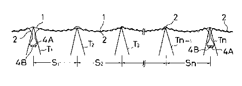
20Fig. 1 is an explanatory view showing an embodiment
of a method of laying an optical fiber according to this
invention;
Fig. 2 and 3 are perspective views showing the state
that the optical fiber is wound on a reel in one step of the
laying method.
DESCRIPTION OF THE PREFERRED EMBODIMENTS
An embodiment of a method of laying an optical cable
in an aerial line will be described in the state that the
optical cable 2 is wound and laid along a~ aerial ground line

;~Z~ 35
-- 3 --
l of zones from steel towers T1 to Tn of power transmission
aerial line as shown in Fig. l.
The length o~ the optical cable is decided from the
total S1 + S2 + ..., Sn of the steel tower interval of the
laying zone and the necessary marginal length, the optical
cable 2 measured in the length is wound on a reel 3, and
optical connectors 4A and 4B are mounted at both ends of the
reel. This work is ordinarily performed in a factory. Then,
the reel 3 is mounted in a winding machine of self-traveling
or towing type, and the machine is moved from one side of the
laying zone, i.e., from the steel tower T1 side in this
example along the aerial ground line l. Thus, the optical
cable 2 is wound and laid on the aerial line l. Since the
optical cable 2 is measured in advance in the necessary
length for the zone to be laidl the optical connectors 4A, 4B
are disposed between the steel tower T1 and Tn of both ends
when the laying work i5 finished.
The abovementioned laying work is also achie~ed in
the adjacent zone. Thus, the optical cables 2, 2 o khe
adjacent zone can be connected merely by connecting the
optical connectors 4A, 4B on the steel towers T1 and Tn in
which the ends of the optical cable 2 are disposed.
In the embodiment described above, the case that the
optical cable is wound and laid from one to the other sides
of the laying zone has been described. However, when the
optic~l cable is laid from the center to the both ends of the
laying zone, the optical cabls 2 is sorted and wound to two
reels 3, 3 as shown in Fig. 3, and the optical connectors 4A,
4B may be mounted at both ends.
According to this invention as described above, the
optical connectors are mounted at both ends of the optical
cable measured in advance in the necessary length, and the

~Z~7~35
optical cable is laid along the aerial line. Consequently,
the optical cable ~etween the adjacent laying zones can be
connected by the connector~ on the support, and the
connecting work can be very simply performed on the support
to shorten the work.
,

Representative Drawing
A single figure which represents the drawing illustrating the invention.
Administrative Status

2024-08-01:As part of the Next Generation Patents (NGP) transition, the Canadian Patents Database (CPD) now contains a more detailed Event History, which replicates the Event Log of our new back-office solution.

Please note that "Inactive:" events refers to events no longer in use in our new back-office solution.

For a clearer understanding of the status of the application/patent presented on this page, the site Disclaimer , as well as the definitions for Patent , Event History , Maintenance Fee  and Payment History  should be consulted.

Event History

Description Date
Inactive: IPC from MCD 2006-03-11
Time Limit for Reversal Expired 2002-03-27
Letter Sent 2001-03-27
Grant by Issuance 1990-03-27

Abandonment History

There is no abandonment history.

Fee History

Fee Type Anniversary Year Due Date Paid Date
MF (category 1, 8th anniv.) - standard 1998-03-27 1998-02-19
MF (category 1, 9th anniv.) - standard 1999-03-29 1999-02-17
MF (category 1, 10th anniv.) - standard 2000-03-27 2000-02-17
Owners on Record

Note: Records showing the ownership history in alphabetical order.

Current Owners on Record
THE FURUKAWA ELECTRIC CO., LTD.
Past Owners on Record
NORIO KATSUOKA
TAKAO IKEYA
Past Owners that do not appear in the "Owners on Record" listing will appear in other documentation within the application.
Documents

To view selected files, please enter reCAPTCHA code :


To view images, click a link in the Document Description column. To download the documents, select one or more checkboxes in the first column and then click the "Download Selected in PDF format (Zip Archive)" or the "Download Selected as Single PDF" button.

List of published and non-published patent-specific documents on the CPD .

If you have any difficulty accessing content, you can call the Client Service Centre at 1-866-997-1936 or send them an e-mail at CIPO Client Service Centre.


Document
Description 
Date
(yyyy-mm-dd) 
Number of pages   Size of Image (KB) 
Cover Page 1993-09-18 1 17
Abstract 1993-09-18 1 21
Claims 1993-09-18 1 32
Drawings 1993-09-18 1 21
Descriptions 1993-09-18 4 133
Representative drawing 2001-10-05 1 6
Maintenance Fee Notice 2001-04-24 1 178
Fees 1997-02-17 1 74
Fees 1996-02-20 1 65
Fees 1994-02-22 1 67
Fees 1993-02-03 1 55
Fees 1995-02-17 1 84
Fees 1992-02-06 1 66