Note: Descriptions are shown in the official language in which they were submitted.
3~
-- 1 --
The present invention relates to telecommunicakions
systems using light radiation guided by transmission
media, and more particularly to a coupler for optical
fibres.
A te~hnical problem to be solved in optical fibre inter-
connection is distribution of optical power from a
transmission medium to a plurality of media, whilst main-
taining uniform the coupling and limiting power loss.
While the loss in case of a coupler between two fibres
only is essentially due to imperfect alignment or match-
ing of the optical fibre characteristics, the coupling
loss between one and a plurality of fibres can be due
also to shadow zones, resulting in some of the optical
input from a fibre failing to be transferred to the out-
going fibres. A good coupler should also maintain theoriginal light beam characteristics unchanged, particu-
larly those relating to modal distribution, i.e. different
order modes propagating in the fibres should not become
mixed, since this may cause inter alia distortion of the
transmitted optical pulses, in case of multimode fibres,
and excitation of non-propagating modes in the case of
monomode fibres.
At the same time, the design and mechanical parts ought
to be as simple as possible and the number of different
materials utilized should be kept ~o a minimum. The
coupler should be insensitive to external mechanical
strains which could give rise to misalignment and hence
power loss.
An optical coupler is described in "Advances in Ceramics",
Vol. II,'~hysics of Fiber Optics" by Kapany, editad by
The American Ceramic Society. This coupler couples a
fibre to two other fibres, by exploiting power reflection
from two semi spherical surfaces, which concentrate the
~2~,Y~
-- 2 --
radiation emitted by one fibre into the other two. This
coupler still presents a number of disadvantages, among
which are:
a~ optical signal distortion due to differing lengths of
the optical pa~hs between the fibres and different
points on the semi-spherical surfaces;
b) the impossibility of coupling to more than two fibres
without fundamental modifications in the geometric
shape of the reflecting surfaces; and
c) sensitivity to mechanical vibration, as individual
fibres and the re1ecting surfaces may undergo rela-
tive oscillation. This is because, in order to opti-
mize the optical path, it is necessary o leave a
certain air distance between the fibre ends and the
reflecting surfaces, as a consequence of which the
coupler canno~ be made in one piece.
Another technique for coupling a plurality of fibres
con6ists of fusing a bundle of suitably prepared fibres,
so obtaining a zone whera there is no differentiation of
the cores. The fused zone is then drawn and possibly
machined. Such a coupler is difficult to make both be-
cause of the necessary preparation of the single fibres,
which must generally be stripped of their cladding, and
because of the necessity for correctly controlling the
fusion step. Such a coupling also tends to cause propa-
gation modes to be mixed.
The present invention seeks to provide an optical coupler
which allows the coupling between a single input fibre
and any desired number of output fibres, which can be
made in one piece so as to control mechanical vibration
problems, which can avoid mixing propagation modes and
which can be constructed compactly (a 6 fibre coupler
3 --
can be housed with a 4 mm side cube). The relative
amount oE radiation collected by each output fibre can
be controlled by a suitable mask, thus permitting certain
optical signal conditioning. It can be made by a tech-
nology similar to that usually employed in the manufac-
ture of lenses.
The present invention provides a coupler for establishing
optical connection between a first optical fibres and a
plurality of further optical fibres, formed by a trans-
parent member in the shape of a paraboloid limited by aplane perpendicular to the paraboloid axis and having an
inwardly reflective curved surface, an array of lenses
having axes parallel to the paraboloid axis, t~e array
being coplanar with the perpendicular limiting plane and
including a first lens coaxial with the axis of the para-
boloid, and centring means for receiving and aligning the
ends of a plurality of optical fibres coaxially with said
lenses, the end of the ~irst optical fibre being located
coaxial with the lens coaxial with the paraboloig axis
so that an image o the fibre end is formed at the focus
of the paraboloid, and the further ~ptical fibre ends be-
ing located coaxial with further lenses in the array such
that radiation parallel to the lens` axes is condensed on
the further fibre ends.
~urther features of the invention will appear from the
following description, by way of example, of an embodi-
ment of the invention with reference to the accompanying
drawings, in which:
Figure 1 is a longitudinal sectional view of an optical
fibre coupler;
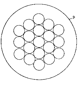
Figure 2 is a plan view of a plate P shown in section in
Figure 1.
~lZ~'~ 3~
The coupler shown in Figure 1 comprises a first part S
made of glass, and having the geometrical shape of a
paraboloid limited by a plane perpendicular to its axis.
The curved external surface is rendered inwardly reflec-
tive towards the concavity of the paxaboloid by deposi-
tion of a suitable reflective material, such as silver
or aluminum. A glass plate P is connected by suitable
cement to the plane surface of the paraboloid S. The
plate has plane parallel surfaces, hemispherical lenses
Ll ... L5 being formed in that surface cemented to the
paraboloid. These lenses are preferably distributed in
concentric rings, with their maximum diameter coinciding
with the 6urface of the plate.
Optical fibres Fl ... ~5 are held in a fixed position
relative to plate P by a suitable centring plate C, with
their axes coincident with those of the lenses. The
plate C is provided with guides for the fibres perpendi-
cular to a plane surface which is cemented to plate P.
The thickness of the plate P containing the lenses depends
on the focal length of the lenses~ since to optimize the
radiation power entering and emerging from the fibres it
is necessary to respect the optical geometry of the sys-
tem. Fibre F3, which has its axis coincident with the
axis of the paraboloid, illuminates a central hemi-
spherical lens L3 from a distance greater than the focaldistance of the lens. The focus of the paraboloid lies
on the image plane of fibre F3, so that the paraboloid
reflects the optical beam as a plane wavefront which in
turn is condensed by the lenses onto the individual out-
put fibres. The device can also operate inversely, i.e.the central fibre can act as a collector of radiation
received from all the other fibres.
An exemplary device couples 19 fibres, one input (or out-
put) fibre and 18 output tor input) fibres, the latter
';i'3~
-- 5 --
being arranged as groups oE 6 and 12 on two concentric
circles. In this case the losses due to geometric fac-
tors can be reduced to a minimum value of 1.4 dB. These
losses will decrease with an increase of the number of
coupled fibres. The plate P used in this example can be
as shown in Figure 2, with lenses symmetrically placed
around the centre. A third cixcle of lenses could be
added to accommodate a numher of additional fibres which
is twice that of the number accommodated by the second
circle, i.e. 24 fibres.
In the present state of glass technology the coupler
dimPnsions and the maximum fibre packing density are
limited mainly by the lenses. A reduction in the size
of these improves the opti~al and geometric characteris-
tics of the optical coupler. One possible method ofmaking hemispherical lenses exploits ion electrophoresis
causing a refractive index variation during manufacture
of glass of suitable chemical composition. A blank for
the forming of the plate P is masked according to a
desired geometry and is immersed into a galvanic bath of
a melt of the diffusing ion. Diffusion laws ensure the
fabrication of hemispherical lenses with graded index.
Such a method is described in "Stacked Planar Optics By
The Use of Planar Microlens Array" by K. Iga et al~
Proceedings of the 10th ECOC '84, Sep~ember 3-6, 1984,
Liederhalle, Stuttgart. As an alternative the lenses can
be directly formed by ion implantation on the plane para-
boloid surface, thus fabricating the entire coupler
optics in one piece.