Note: Descriptions are shown in the official language in which they were submitted.
-1
TITL O~ _ IE INVENTION: AN ARRANGEMENT IN A UNIT ~IAVING
A IIEA~-E,XC~IANGE FUNCTION.
Technical Field
The present invention relates to an arrangement in a
unit having a heat-exchange function and comprising
heat-emitting and heat-absorbing means which are expos-
able to an incoming flow of medium entering the unit.
These means change the energy of the incoming ~ledium
flow, and the resultant flow is hereinafter referred to
as "a medium flow exiting from the unit'`.
The arrangement according to the present invention can be
used in conjunction with a gaseous or liquid medium. For
the sake of simplicity, however, the invention will be
described later with reference to an air-circulation,
cooling system having a cooling element which is posit-
ioned above and/or beneath an array of electronic equip-
ment which generates heat when working~
sackground Prior ~rt
:
Cooling sy~tems which function with gravitational convec-
tion in accordance with the above principles and cooling
elements of the aforesaid kind are known to the art.
For example, it is known to cool arrays oE electronic
equipment, such as telephone equipment, arrays in rows,
side-by-side, with the aid of a cooling system which
cools the flow of air heated by the equipment in oper-
ation and which includes a cooling element or cooling
unit arranged above passageways located between mutual-
ly adjacent rows of equipmen-t.
'rhc purpose of such a systcm is to crcate gravitational
`73
--2--
convection cond.itions with the aid of hot air flows,
such that an air flow heated by..an array , or arrays, of
electronic equipment when in operation is able to rise
and enter the cooliny elemen-t, to be cooled therein, this
somewhat cool airflow exiting from the cooling element
and sinking down gravitationally towards the floor sup-
porting the equipment and passing from said floor into
the array of equipment, where it again takes~up heat, to
form an upwardly rising heated air flow.
One such known system is retailed under the tradename
"ERICOOL" through RIFA AB, Stockholm, Sweden.
Other systems for cooling arrays of elec-tronic equipment
are also known to the art.
For example, systems are known in which cooling elements
are placed immediately above an array of electronic
equipment.
Sys-tems are also known in which one or more cooling ele-
ments are placed in the proximity of one or more groups
of components, where a number of such groups forms the
aforesaid array. In this way there is obtained in the
immediate vicinity of the heat-generating components a
cooling effect which can be reyulated in response to the
amount of heat generated.
In addition hereto, there are known to the art office
ventilating systems, referred to as "induction systems",
which include blower nozzles so arrannged as to entrain
air ~rom the room to be ventilated by co-ejection,
thereby to ensure good admixture of the circulating room
air with ventilation air delivered to the system, or
.
~ 5
system apparatus, from a central air processing unit
through a system o conduits, thë ventilation air pref-
erably being brought to a temperature of ~10C - +15C
in said unit.
Summar of the Present Invention
Y
With regard to the presen-t s-tate of the art as expressed
above it will be seen that one related -technical problem
resides in the provision of an arrangemen-t in a unit
which is adapted for heat-exchange purposes and incor-
porates heat-emitting or heat-absorbing means exposable
to an incoming flow of medium entering the unit, and in
which unit the aforesaid means change the energy content
o~ the incoming flow of medium to form an exiting medium
Elow which leaves the unit, and to provide in conjunc- ;
tion therewith conditions for generating a urther flow
of medium which can be readily delivered to the incoming
medium flow entering the unit, so as to ensure thereby
that no additional space is required around the unit for
generating forced~flow conditions.
Another technical problem encountered in an arrangement
of the aforesaid kind is one of creating simple cond- -
itions which will enable said further medium flow to be
so directed that it is able to force the incoming medium
flow through the unit wtih the aid of a co-ejector eff-
ect, so as to create thereby air circulation without
requiring therefor the use of large fan assemblies for
forcing and directing the incoming medium flow through
the unit.
A further technical problem is one of creating in an
arrangement of the aforesaid kind, while observing the
aforementioned technical evaluations, conditions which
will extend -the stay-time of the incoming med.~um flow
a~
_9
and preferably also lengthen the path of travel of the
medium along cooling fins provl~ed in the unit/ so as to
create conditions Eor more effective emission or absorp-
tion of thermal energy during the time the medium flows
through the unit.
Another technical problem is one of providing conditions
in an arrangement of this kind which enable the exiting
medium flow to leave the unit in a direction which con-
forms substantially to the direction of the incoming
medium flow, despite the fact that the medium flow is
deflected from said direction during its stay-time in
the unit.
Still another technical problem resides in the provision
of conditions which will enable the exiting 10w of med-
ium to be controlled or guided as a whole, or to be
divided into part flows capable of being directed to-
wards two arrays of electronic equipment, each located
on a respective side of the unit.
In those embodiments where the further medium flow or
further medium Elows is (are) delivered through delivery
pipes perforated with holes, a further problem resides
in adapting the cross-sectional area o~ the hole and/or
its location correctly with regard to the aforesaid
conditions provided for solving the abovementioned
technical problems.
It has been established that -the aforesaid hole, or
holes, should be very fine and that consequently there
is a risk of tlle holes becoming blocked with foreign
particulate substances during operation. Consequently,
~ prime pro~lem exists in the ability to use finely
~5--
perforated pipes while, at the same time, providing
conditions which will ensure that the sum o~ the mass
weight of respective medium :Elows per unit of time
multiplied by their velocity will present a value, cal-
culated per square meter of cross-sec-tional area at right
angles to the direction of the air flow, which lies
within a given limit range relevant to an effective
transfer o~ heat between said-emitting or heat-absorbing
means and the incoming air flow~
In the case of present-day cooling systems which operate
with circulating air and which comprise a cooling element
or cooling unit intendedfor cooling an array of electron-
ic equipment, and placed above and/or beneath the array,
such that, for e~ample, a flow of air cooled by the cool-
ing element or unit is able to sink down towards
(against) or around the array of equipment, preferably
between two such arrays, while a flow of air heated by
the equipment is able to rise upwards towards the cooling
element, it is a recognized fact that the cooling effect
afforded by these systems is not sufficient to meet
prevailing needs, and hence a qualified technical prob-
lem resides in the provision of conditions for improving
the cooling efficiency of such systems with the aid
of simple means located within the external defining
surfaces of the cooling unit or element.
Another technical problem associated with known cooling
systems of the aforesaid kind resides in the difficulty
in providing conditions which will ensure that the
somewhat cooled air 10w is actually ~uided into and
passes through the array of electronic equipment in a
manner to cool efectively the heat-generatiny components
thereof, since na-tural convection has not been found
,
~2~ as
--6~
sufEici.ently e.EEective to provide the degree oE cooling
required; the use o.~ yowerEul Eans for this purpose is
both expensive and space consuming. Consequently, a
further qualiEied technical problem resides in the
provision of simple means which will forcilbly control
or guide both the cooled and the heated air flows in a
manner which will enable grea-ter quantities of cooled
flowing air to be used to cool the electronic components.
Another technical problem is one of creating conditions
which will enable existing known air-cooling systems to
be modified with simple means which require no external
space, without requiring further work on the system, and
where additional measures can be concentrated solely on
the cooling element.
Still ano-ther technical problem resides in creating, with
the aid of simple means, conditions which will enable
the cooling ability of a cooling system to be adapted
effectively to prevailing loads on the electronic com-
ponents of the array, or arrays, of equipment when in
operation, and to fluctuations in the heat generated by
the components.
A further technical problem is one of providing cond~
itions which will enable each electrical component of
the electrical equipment to operate in an environment
of relatively low ambient temperature, so as to create
thereby conditions which will increase the operational
durability of the equipment and its components and to
reduce the influence of such factors as those liable to
increase the frequency at which faul-ts may occ~r.
A fur-ther technical problem is one of creating cond-
', . '
,
'Y~
--7--
itions which will enable a cooling element constructed
in accordance with the invention to he adapted readily
for manufacture with the use of known cooling element
manufacturing methods.
Another technical problem encountered with cooling ele-
ments of the aforedescribed kind is one of creating con-
ditions which enable a very small, positively guided air
stream to guide the heated air flow into the cooling
element through the agency of an ejector effect, so that
the heated air flow is cooled to a greater extent than
is otherwise normal when solely natural convection
conditions prevail.
.~
Solution
Thus, the present inven-tion relates to an arrangement for
use in a unit which is adapted to provide a heat-exchange
function and which incorporates heat-emitting and heat--
absorbing means exposable to an incoming medium f low ent~
ering the unit, such as to impart to the medium f low a
changed energy content in the form of a medium flow leav-
ing the unit.
In accordance with the invention a fur-ther flow of med-
ium is delivered under pressure to the incoming medium
flow in the region of the unit, or at least in the im-
mediate vicinity of said region, this further flow of
medium being so directed as to force the incoming med-
ium flow through the unit by means of a co-ejector
effect, and particularly to change the direction of the
incoming medium flow through the unit, so as to extend
the stay-time of said flow in said unit.
In accordance with the invention the unit comprises a
.
,
s
plurality of mutually adjacent pipes which extend through
a plurality of cooliny fins, thë Eurther Elow oE medium
being genera-ted through holes formed in two or more of
these pipes.
In accordance with one embodiment of the invention, one
and the same pipe is provided with a plurality of holes,
each of which is located between cooling fins. Pref-
erably, one or more of said holes is ~are) located bet~
ween mutually adjacent cooling fins.
When one or more holes is (are) located between mutually
adjacent fins, that section of the pipe located within
one or more defining fins is r,referably imperforate.
In accordance with one preferred embodiment of the in-
vention the further medium flow is directed from a irst
edge part of the unit, substantially transversely of the
incoming medium flow, although with a directional com-
ponent conforming to the direction of the incoming flow,
the incoming medium flow being deflected to pass in a
direction along the fins instead of passing across the
same.
n advantage i5 afforded when the incoming medium flow is
mixed with the further medium Elow. Consequently, in
accordance wi.th the invention deflecting means are ar-
ranged adjacent said edge part of the unit, therewith to
mpar-t to the exiting medium flow a direction which con-
forms substantially with the direction of the incoming
medium flow.
'l'o -this cnd, the deflecting means is preferably located
at the edge part located opposite the first edge part
JJ~s
from which the further medium flow departs.
~lthough the deflected means is preEerably located solely
adjacent one edge part of the unit, it is possible, in
accordance with the invention, to arrange for a plurality
of further medium flows to depart from opposing edge
parts and to be direc-ted along the cooling fins, by
providing suitable deflecting means on both sides of the
unit.
It is also possible within the scope of the invention to
permit the further medium flows to be directed essential-
ly in a direction conforming with the direction of the
incoming medium flow and the medium flow exiting from
said unit.
The invention is particularly suited for application in
cases where the medium flows comprise a gas and/or a gas
mixture, in the latter case preferably air. It is prop-
osed herewith that a further air 10w, or the aforesaid
further air flows, are supplied between the fins via a
system of pipes having a pipe-pressure beneath 50,000Pa.
In this case it is proposed that the further air flow
or the aforesaid further air flows are supplied through
a pipe perforated with holes having a cross-sec~ional
area beneath 200mm2. Preferably the hole diameter is
beween 0 5 and 5mm, when the holes are o circular
cross-section.
The further air 10w or air 10ws are so selected that
the sum of the mass weight per unit of time of repective
10ws multiplied by their velocity has a value smaller
than 300 and greater than 0-1, preferably a value lying
within the range of 5 - 30 calculated per square meter
.
:
- 1 0 -
of cross-~ectional area at right angl~s to the direction
of the air flow.
The arrangement according to the invention is particular-
ly suitable for use in a cooling element or cooling unit
which is intended for cooling an array of electronic
equipment and which forms part of an air-circulation
cooling system, in which the cooling element is position-
ed above the array of equipment so that, for example, an
air flow cooled by the cooling element is able to sink
down onto or around the array of equipment, preferably
b~tween two arrays, while an air flow heated by the com-
ponents of the said equipment in operation is able to
rise upwards -towards the element.
When the arrangement according to the invention is incor-
porated in a system of this kind, a further air flow is
delivered to the heated air flow in the region of the
cooling element, this further air flow being so directed
as to force the heated air flow throu~h the cooling
element with the aid of a co-ejector effect, the heated
air flow entering the cooling element, e.~ rom above
or from the side, while the medium flow exiting from the
unit can be directed downwardly and preferably along the
side of the electronic equipment.
In those cases in which two arrays of electronic equip-
ment are spaced from one another and the cooling element
is located between said arrays, it is proposed in ac~
cordance with the invention that at least two further
air flows are generated in one and the same cooling
element, so that the air flow cooled by said cooling
clemellt is divided in a controlled fashion into part--
flows, each of which is directed along a respective
.
, ~ , ' . ' . ' ' ' '
,
-1 1-
array of equipment. In this case, each of the further
air flows is generated between ~wo, mutually different
cooling fins in the cooling element.
In accordance with another embodiment of the invention,
the furhter air flow Ls caused to mix with the heated air
flow in the cooling element so as to form a cooled air
flow, which is caused to pass through the unit at a vel-
ocity below 50m/sec, preferahly between ~ and 5m/sec.
In addition, the further air flow shall be so arranged as
to deflect the heated air flow in order to obtain a long-
er path of travel along the fins than that obtained in
the absence of a further air flow, which means that the
heated air flow will normally be directed transversely
of the longitudinal extension of the fins. The propor-
tion of the further air flow in the cooled air flow shall
be less than 25%, preferably less than 10~.
Advantages
The advantages primarily characteristic of an arrangement
according to the present invention reside in the pro-
vision oE conditions which enable the incoming medium
flow to be forced, with the aid of an eiector effect,
through a unit having a heat-exchange function, without
requiring the provision of means herefor externally of
the unit and/or in its immediate vicinity, while increas-
ing the ability of the unit to emit or absorb heat.
The primary characterizing features of an arrangement
.lc(ording t~o t.hc prcscnt invcnt:ion arc sct forth in thc
:
Q~
-12-
characterizing clause o:E the Eollow:ing Claim 1.
Brief Description of the Drawings
A preferred ernbodiment of the invention will now be des-
cribed in more detail with reference to the accompanying
drawings, in which;
Figure 1 is a greatly sim~lified front view of a known
cooling system used in conjunction with telephone equip-
ment;
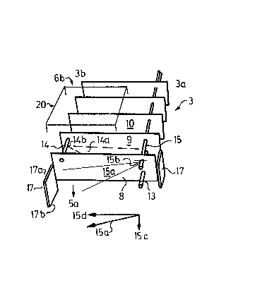
Figure 2 is a simplified perspective view of a cooling
element according to the present invention for use with
the system illustrated in Figure 1;
Figure 3 is a plan view of a cooling fin incorporated in
a unit accordi.ng to Figure 2; and
Figure 4 illustra-tes the velocity profile of a medium
flow exiting from the unit when utilizing a further air
flow.
Description of a Preferred Embodiment
Figure 1 illustrates schematically and in side view
electronic telephone e~uipment provided with a cooling
system for cooling an array of electronic devices which
incorporate electronic components and the like. The
electronic equipment mounted on printed circuit cards,
is placed in frames or racks arranged in rows, designated
1 and 2. Defined between mutually adjacent rows of
frames or racks, such as rows 1 and 2, is a passageway 4
(for service personnel and li.ke attendants). A cooling
.
-13-
element 3 is mounted directly above a respective passage-
way, adjacent a sealing struc-tu~e referencecl 4a. The
floor structure supporting the racks is referenced 4b.
The cooling element 3 forms part of a cooling system in-
tended for cooling one or more arrays oE equipment 2, by
air circulation or gravitational convection, in wh.ich
system the cooling element is either located above a
singl.e row of racks or between two mutually adjacent rows
of racks, as in the case of the preferred embodiment.
It will be understood that the cooling element can be
located immediately above the rack 1, with the direction
in which medium passes through the element 3 being
opposite -to that illustra-ted, the cooled air flow dividing
at a location adjacent the ceiling 4a and being permitted
to sink down into the respective passageway on either
side of the row of racks 1.
The following description is made with reference to the
alternative embodiment illustrated in Figure 1.
;
In this way conditions are created ~or enabling an air
flow 5, 5a, 5a', cooled by the cooling element 3, to sink
down towards a respective array, or preferably towards
the floor 4b of the passageway 4 be-tween two arrays 1 and
2. A respective air stream 6a, 6b, and 7a, 7b heated by
an array 1 and 2 in operation is now able to rise up
through said array and over the electronic components
incorporated therein, -therewith entraining cooling air
through the array of electronic equipment and towards the
cooling element.
:
q'he inventi.on is based on the concept that the cooLing
- 1 'I ~
effect afforde~ by the cooliny elemen~ 3 on the heated
air Elow can be improved by arranging for said air flow
to be delivered to the cooling element 3 in the form of
a forced air stream, with the aid of an ejector effect,
although with a longer, or extended, stay-time in the
cooling element and/or a longer travel path with respect
to the passage of the air flow through the cooling ele-
ment 3~
Since the presPnt invention relates to an arrangement for
use in conjunction with the cooling elQment 3, a cooling
element constructed in accordance with the invention is
illustrated in perspective in Figure 2, in a somewhat
simplified ~orm.
The cooling element illustrated in Figure 2 comprises, in
a ~nown manner, a pluarality of mutually adjacent fins 8,
9, 10. The fins may present corrugated surfaces, or may
be given a form different to that illustrated. Each fin
is provided with a number of holes ~or accommodating a
system of coolant pipes. The pipes included in the pipe
system are normally placed closer together than illust-
rated in Figure 2, and for the sake of simplicity it is
assumed that coolant flows solely through pipe 13. The
fins 8, 9 and 10 are cooled by this coolant pipe.
Further pipes 14 and 15 also pass through the fins 8, 9
and 10, these further pipes being normally intended for
conveying coolant and Eor cooling the fins. However, in
accordance with the invention, these further pipes are
perforated and supplied with air under pressure.
Y'hus, Figure 2 illustrates an arrangement in a heat-ex-
change assemb:Ly, in which heat-emitting or heat-absorbing
as
-15-
means 8, 9, 10, 13 incorporated ln the cooling element 3
can be exposed to a flow o:E medium 6b entering the cool-
ing element, said means being effec-tive to change the
energy content of the medium flow, such as to produce
colder air Elows 5, 5a and 5a', which exit from the cool-
ing element.
As will be seen from Figure 2, a further flow of medium
15a is delivered to the aforesaid incoming medium flow,
in the region of the cooling element 3.
This further air flow 15a is so directed as to force the
incoming medium flow 6b through the cooling element, with
the aid of an ejector effect.
As beforementioned, the cooling element 3 comprises a
plurality of mutually adjacent coolant pipes, of which
only the pipe 13 is shown, the coolant pipe, or pipes,
ex-tending through a plurality of fins, these fins also
being provided in greater numbers than those illustrated,
and the further air flow being generated through holes
provided in one or more of said pipes.
In Figure 2 one such further air flow i5 designated 15a,
and another is designated 14a.
One and the same pipe, e.g. the pipe 14, may be provided
with a plurality of holes, each located between two fins
8 and 9. For the sake of clarity only one hole, 14b, is
shown in Figure 2.
,
It lies within the scope of the invention to locate one
or more holes between mutually adjacent fins, such as the
hole 14 between ~he fins 8 and 9. ~lowever, when one or
.
-16-
more holes is (are) located between mutually adjacent fins
8 and 9, it also lies within -the concept of the invention
to leave the pipe free of holes, i.e. imperforate, in the
region defined by certain mutually adjacent fins, i.e.
between the fins 9 and 10, or by a group of fins, with
the exception of those regions in which an air flow sim
ilar to the air flow 15a is to be generated.
It also lies within the purview of the invention to loc-
ate one or more holes between mutually adjacent fins and
to leave imperforate a section of the pipe between selec-
ted mutually adjacent fins, or a sequential arrangement
of fins extending from the perforated region o~ the pipe.
Counter-directional medium flows for the various fins are
used to split the exiting flow of cooled air into two
part-flows 5a and 5a', each part-flow being directed
along a respective row of racks. When the further flows
of medium are permitted to act uniformly within the area
confined by the same fins, there is generated a centred
air flow 5.
:
The effect and direction of tl1e air flows can be varied,
by varying the pressure in the pipe 15 in relation to
the pressure in the pipe 14.
It is also possible, in accordance with the invention,
to readily adapt the cooling potential of the cooling
system to the prevailing load and to variations in said
load, simply by varying the pipe pressure.
As will be seen from ~igure 3, the further medium flow,
or air flow 15a, is directed from one edge part 3a of
thc cooling uni-t 3, substantially transversely to the
v~ 5
-17-
.incoming ~low of medium 6b, although wi-th a directional
component conforming to the direction 6b of the incoming
medium flow.
This directional component is designated 15c in Figure 2.
The directional component extendlng transversely to the
medium flow 6b is designated 15d.
It will therefore be apparent that the incoming medium
flow 6b will be deflected to the left in Figure 3 by
the further air flow 15a, therewith to mix with the fur-
ther medium flow 15a. ~ means 17 for deflecting the mix-
ed flow of media is arranged adjacent the opposing edge
part 3b of the cooling element 3, said means 17 being
located in that edge part 3b which lies opposite the
edge part 3a from which the further medium flow 15a
exits.
According to one embodiment of the invention the deflect-
ing means 17 is arranged solely adjacent one edge part
and between respective fins. Alternati~ely, deflecting
means 17 may be located externally of all of said fins
on each side of one and the same fin. It will be seen
from Figure 2 that ~urther medium flows are arranged to
depart form opposing edge parts, such that the medium
flow 15a departs from -the edge part 3a and the medium
flow 14a from the edge part 3b, both said medium flows
being directed along the fins.
When a plurality of pipes 14, 15 are orientated in one
and the same horizontal plane/ it may be suitable to
allow the further medium flow, or further medium flows,
to pass substantially in a direction corresponding to
the direction of the incoming medium flow 6b.
.
'., ', ' ' ~ ' ' ' ',,
.
.
5~
-18-
It is assumed here tllat the medium flow of the illustrat-
ed embodiment is a gas flow and~or a flow oE gaseous mis-
ture, preferably air, and that the further medium flow
15a, or further medium flows 14a, 15a, is (or are) del-
ivered to the cooling element 3 through a sys-tem of pipes
14, 15 having a pipe-pressure below 50,000Pa, preferably
below 50 and 5,000Pa.
Practical tests have indicated that the pipe pressures
should lie between 2,000 and 5,000Pa.
The furhter medium flow, or medium flows 14, 15a, is(are)
delivered through a pipe 14, 15 provided with holes 14b,
15b having an area smaller than 200mm . The holes are
preferably circular in cross-section and have a diameter
ranging from 0-1 to 10mm, preferably from 0-5 to 5mm.
The velocity of the medium flow adjacent respective holes
shall be below the speed of sound.
When there is introduced a definition which establishes
the mass weight of the medium flow per unit o~ time mult-
iplied by its velocity for a given surface area (calcul-
ated per square ~eter of cross-sectional area at right
angles to the direction of the air flow), referenced 20
in Figure 2, the further medium flow, delivered to said
surface area shall be so selected that the sum of the
mass weight of respective medium flows per unit of time
multiplied by their velocity, applicable to the nozzle-
like holes 14b and 15b, has a value beneath 300 and
above 0-1, preferably a value lying within the range of
5 - 30kgm/s .
Finally, Figure 4 shows a velocity profile of the medium
~' '
.
~2~
-19-
flow 5a departing from the coolir}g element, from which it
can be seen that propagation oE~`-the medium flow is some-
what greater at -the edge part 3b of the cooling element
than at its edge part 3a. This fact is preferably util-
ized by placing the edge part 3b in the immediate proxim-
ity of the equipment 1, in the manner illustrated in Fig-
ure 1, which means that the flow of air exitiny from the
cooling element will creep along the surface -towards the
passageway 4 adjacent the equipment 1, therewith forming
the medium flow 5b.
Because the air jet or air flow 14a issuing through the
: nozzle-like hole 1~b is directed between the fins 8 and 9
: in an opposite direction it will produce a velocity pro-
file which is the mirror image of that shown in Figure 4.
The jet o:E medium 14a will impart to the medium flow 5a a
high velocity in the vicinity of the equipment 2.
When a cooling element constructed in accordance with
Figure 2 is used as a cooling element 3 in the arrange-
ment of Figure 1, it will be seen that each of the furth-
: er air flows is so directed as to direct the respective
air lows 5a and Sb' cooled by the cooling element along
the arrays of equipment. In addition, when a single
cooling element is located between two mutually adjacent
rows of equipment, at least two further air flows can be
created such that each of the air flows 5a, 5' cooled by
the cooling element is directed along its respective row
of equipment 1, 2. Each of the urther air flows is gen-
erated between two fins on the cooling element. Alter-
natively, each air flow can be placed within a region
defined by a plurality of mutually adjacent fins.
In accordance with one embodiment of the invention, the
.
. .
-20-
further a:Lr flow 19a shall m:ix w.ith the heated air Elow
6b adjacent the cooling element and form a cooled air
~low 5a' having a velocity beneath 15m/sec. The further
air flow 14a also deflec-ts the flow of heated air 6b in
this case, so that -the path travelled by the air flow 6b
along the Eins is longer than would otherwise be the case
in the absence of such a further air flow. Moreover the
proportion of air from the Eurther air flow 14b in the
cooled air flow 5a' shall be less than 15~.
The deflecting means 17 may have the form of a plate,
which is preferably attached to one or more fins and
which extends from the central region of respective ins,
down beyond the lowermost edge thereof.
An advantage can be gained by placing the top edge 17a
of the deflecting means 17 on a level with the uppermost
e~tension of the flow lobe. Similarly, the bottom edge
17b of the deflecting means 17 may be placed on the level
of the lowermost extension of the flow lobe. The edge,
however, is preferably shorter than this, as illustrated
in Figure 3.
The deflecting means 17 may extend along all of the fins,
or may be constructed to cover solely the interspace
between those fins located in regions where holes 15b are
provided.
The deflecting means may also have the form of a plate
which stands free form the fins and which is mounted for
vertical movement on support means, not shown.
'rhe above description oE the deflecting means 17 also
applies to the means 17'.
..
2 1 -
When the cleflecting means 17 is ~ositionecl in the manner
illustrated in Figure 3 there is' a velocity profile 5a'
according to Figure 4.
This shows clearly the direction of the outgoing stream
5a, towards and along the row oE equipment 1.
It will he appreciated that a change in pressure in the
pipe 15 will result in a change in the velocity profile,
which affords the possibility of regulating the ejector
effect and the forcing velocities of incoming flows of
medi.um, e.g. in dependance on prevailing loads.
It will be understood that the invention is not restrict-
ed to the described and illustrated embodiment, and that
modifications can be made within the concept of the in-
vention as defined in ehe iollowing Claima.
:
- ' .