Note: Descriptions are shown in the official language in which they were submitted.
;~6~
-- 1 --
Pressure-controlled heat pipe
The invention relates to a pressure-controlled heat pipe
comprising a closed recipient containing a heat carrying
medium, with a heat source where the heat carrying medium
vaporizes, and a heat drain constituted by a cooling zone,
a non-condensable inert gas being intended to be fed into
the recipient under controllable pressure at the upper end
of the cooling zone.
Pressure-controlled heat pipes are for example known from
the periodical "Warme- und Stoff~bertragung", vol. l9, 1985,
pages 67 to 71. The temperature of such heat pipes is in-
fluenced by the size of an inert gas column in the cooling
zone. If the temperature of the heat furnace is to be raised,
the inert gas pressure is increased, by which the cooling
surface which can be reached by the carrying medium,is reduced.
It has been found, especially for low operation pressures,
that a mist zone develops in the cooling zone at the inter-
face between the vaporized heat carrying medium and the inert
gas and that vapor droplets can move far into the area of
the inert gas column. It can then happen that the vapor not
only condenses at the substantially cooler wall in the area
of the inert gas column, but is even deposited as a solid
material. This effect is still increased by the natural con-
vection of the inert gas, which mounts in the axial area
of the cooling zone and drops down again in the cooler wall
area.
This danger is particularly present during a controlled trans-
ition of the heat pipe to a lower temperature, because then
part of the inert gas is drawn off.
. ~ , .
':
7~
-- 2 --
It is the object of the invention to improve a heat pipe
such as described above in 6uch a way that deposits of solid
materials in the cooling zone cannot happen any more, even
in cases when the pressure of th0 inert gaS is changed quickly
for control reasons.
This object is achieved according to the invention by the
fact that a thermally conductive displacement body extends
downwards from the upper part of the cooling zone along its
central area and that this displacement body carries at least
in its upper part deflection sheets which divide the space
between the cooled wall and the displacement body into a
plurality of interconnected volumes. Preferably, these de-
flection sheets are helical ribs.
The function of the helical ribs is, on the one hand, to
lengthen the way of the condensate droplets on their way
up, so that they do not reach any more the coldest area of
the cooling wall, and on the other hand, to hinder the con-
vection flow of the inert gas in the axial area of the cooling
zone.
The displacement body contributes to the solution of the
problem attacked by the invention in that, on the one hand,
it occupies the axial area of the cooling zone and thus de-
flects at an early moment the condensate droplets in the
direction of the cooled wall, and, on the other hand, by
the fact that it holds the area of the cooling ~one above the
vapor zone at a high temperature, at which solid deposits
are impossible.
Preerably, the helical ribs have a roof-shaped inclination
to the outside, so that condensate can flow off by gravity
towards the chimney wall.
.
,. .
' . ' . ' : '
-- 3 --
It is not nccessary, but for manufacturing reasons it is
useful, to form the helical ribs as single-threaded screw.
It would for example also be possible to interrupt the rib
structure and to form at least two successive single~threaded
screws, one of which could have a right-handed helix and
the other a left-handed helix,or one of which could have
a larger screw-thread than the other.
The invention will now be described in detail with respect
to a preferred embodiment and with reference t~ the drawings.
Fig. 1 shows a sectional view of a heat pipe furnace with
a pressure controlled heat pipe according to the invention.
Fig. 2 shows, at a larger scale, a detail of fig. 1.
The heat furnace shown in fig. 1 consists of a double-walled
horizontal heat pipe 1, which coaxially surrounds a furnace
channel 2. In the area between the two walls of the heat
pipe 1, there is a heat carrying medium, for example water,
caesium or sodium, which vaporizes at a heat source 3 and
condensates at a heat drain 4. The heat source is for example
a resistance heating which is inserted into an insulation
5 surrounding the heat pipe 1 and which heats the heat pipe
fro~ the outslde. The heat drain 4 is formed bv a chimney
which is connected to the heat pipe and protrudes at the
top from the insulation 5. The outer wall of the chimney
is cooled in its upper area, for example by means of a water
cooling device 6. An inert gas duct 14, for example a helium
duct, by which the uppermost area of the chimney can be sup-
plied with an inert has column 8, ends at the cover 7 of
the chimney. By an appropriate choice of the helium pressure,
the interface layer9 between the vaporized heat carrying medium
in the heat pipe 1 and the inert gas column can be displaced
vertically, so that a more or less large area of the cooled
~'7/~
- 4 -
wall can become effective ~5 A heat drain for the heat carry-
ing medium. The helium ~upply is carried out by ~ control
circuit ~not ~hown) which controls the temperature in the
Purnace 2 close to a nominal temperature.
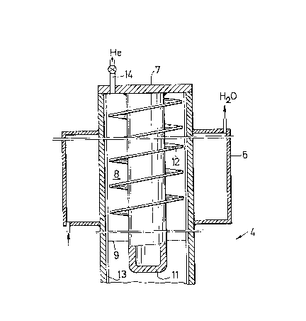
Fig. 2 shows at a larger scale the upper end of the chimney 4
with the water cooling device 6 and the interface layer 9 bet-
ween the inert gas column 8 and the vapor of the heat carry-
ing medium. A displacement body 11 penetrates axially into
this chimney from above and through a cover 7, this displace-
ment body consisting of a thermally conductive metal. l'he
displacement body extends belo~w the minimum level of the inter-
face layer 9, so that its tip is always immerged in the vapo-
rized heat carrying medium~ The upper half of this displace-
ment body carries helical ribs 12, which almost reach the
wall of the chimney which is supplied with capillar grooves 13.
The chimney insert according to the invention deflects the
droplets sidewards and reduces the convection effect, as
the vapor particles are quickly deviated from the axial area
to the outside in the direction of the cooled chimney wall.
At the same time, the displacement body 11, the lower end
of which is immerged in the hot vapor of the heat carrying
medium, holds the helical ribs at a hish temperature with
respect to the wall, so that there is no risk of solid depo~
sits, which might render the furnace unusable. These influences
of the chimney insert according to the invention thus promote
the stability under normal conditions.
When working conditions are voluntarily changed, in particu-
lar when the furnace temperature is lowered by reducing the
inert gas column, the danger of condensate droplets penetrat-
ing into the upper areas of the chimney is also reduced,
whereas without the insert according to the invention, in
this case, con~ensate droplets can even penetrate into the
~6~
-- 5
helium duct 14~
~inal~y, the chimney insert according to the :invention brings
security advantages in the case of an accident, when the
helium duct breaks. In this case, the rising vapor flow must
run through all the helix loops before it can escape through
the broken helium duct. Thus, the insert acts as a condensa-
tion trap and prevents the escape of the heat carrying medium.
The invention is not limited to the embodiment described
in detail. Thus, the heat pipe can have another form than
that of a double-walled coaxial pipe. The heat pipe need
not lie horizontally, but can also be inclined or stand up
vertically. While it is important for a horizontal instal-
lation of the heat pipe that all inner walls are provided
with capillar structures, so that all the walls are constant-
ly wetted by liquid heat carrying medium, in a vertical in-
stallation, the wetting could be carried out without the
capillar structures only by means of gravity. The chimney
could also be mounted on the heat pipe in an inclined po-
sition, provided that it is positioned above the heat pipe.
The helical ribs can be replaced by elements with a different
shape, for example by deflection tools of pagoda shape, which
act as an obstacle for the vapor flow and which alsG divide
the annular zone between the displacement body and the cooled
wall into a plurality of interconnected partial volumes.
Depending on the admissible pressure losses along the cooling
zone, the helical screw can be shaped as a scre~ th several
threads, which can have a larger pitch than a one-threaded
screw without increasing the partial volumes.