Language selection

Search

Patent 1267435 Summary

Third-party information liability

Some of the information on this Web page has been provided by external sources. The Government of Canada is not responsible for the accuracy, reliability or currency of the information supplied by external sources. Users wishing to rely upon this information should consult directly with the source of the information. Content provided by external sources is not subject to official languages, privacy and accessibility requirements.

Claims and Abstract availability

Any discrepancies in the text and image of the Claims and Abstract are due to differing posting times. Text of the Claims and Abstract are posted:

  • At the time the application is open to public inspection;
  • At the time of issue of the patent (grant).
(12) Patent: (11) CA 1267435
(21) Application Number: 1267435
(54) English Title: METHOD AND MEANS FOR USE IN THE INSTALLATION OF PLASMA GENERATORS IN SHAFT FURNACES
(54) French Title: METHODE ET DISPOSITIF INTERVENANT DANS L'INSTALLATION DE GENERATEURS DE PLASMA DANS DES FOURS A CUBILOT
Status: Expired and beyond the Period of Reversal
Bibliographic Data
(51) International Patent Classification (IPC):
  • F27B 1/16 (2006.01)
  • C21B 5/00 (2006.01)
  • H05H 1/26 (2006.01)
  • H05H 1/34 (2006.01)
  • H05H 1/40 (2006.01)
  • H05H 1/50 (2006.01)
(72) Inventors :
  • THORNBLOM, JAN (Sweden)
  • ASTNER, GUNNAR (Sweden)
(73) Owners :
  • SKF STEEL ENGINEERING AB
(71) Applicants :
  • SKF STEEL ENGINEERING AB (Sweden)
(74) Agent: SMART & BIGGAR LP
(74) Associate agent:
(45) Issued: 1990-04-03
(22) Filed Date: 1985-03-25
Availability of licence: N/A
Dedicated to the Public: N/A
(25) Language of filing: English

Patent Cooperation Treaty (PCT): No

(30) Application Priority Data:
Application No. Country/Territory Date
84 05 229-9 (Sweden) 1984-10-19

Abstracts

English Abstract


ABSTRACT
TITLE: "A METHOD AND MEANS FOR USE IN THE INSTALLATION OF
PLASMA GENERATORS IN SHAFT FURNACES"
The invention relates to a method and a means for faciliting
the replacement of plasma generators and for minimizing the
heat losses during installation of a plasma generator in a
shaft furnace, particularly for plasma generators of the type
comprising cylindrical electrodes between which an electric arc
is generated, the bases of the arc being caused to rotate by
means of electric field coils arranged around said electrodes.
To achieve this at least the field coil (7) surrounding the
electrode nearest to the nose (12) of the plasma generator,
together with its connections for coolant and electricity, is
permanently secured in the wall (1) of the shaft furnace in
conjunction with the opening (6) for insertion of the plasma
generator (11) into the shaft furnace.


Claims

Note: Claims are shown in the official language in which they were submitted.

- 6 - 24992-118
THE EMBODIMENTS OF THE INVENTION IN WHICH AN EXCLUSIVE
PROPERTY OR PRIVILEGE IS CLAIMED ARE DEFINED AS FOLLOWS:
1. A method for installing a plasma generator in a furnace
wall, comprising:
providing a plasma generator having electrodes for
generating an electric arc therebetween and having a nose portion
which comprises one of said electrodes;
providing an opening in said furnace wall for said
plasma generator;
fixably mounting in said opening a field coil arranged
to cooperate with one of said electrodes to effect rotation of
said electric arc and a sealing means for effecting a gas tight
seal with said plasma generator; and
inserting said nose portion of said plasma generator
through said sealing means and into said field coil.
2. The method of claim 1, wherein at least one of said
electrodes is a cylindrical electrode.
3. The method of claim 2, wherein said sealing means is a
sluice valve.
4. The method of claim 1, wherein said opening in said
furnace wall is fitted with a tuyere.
5. The method of claim 2, wherein said opening in said
furnace wall is fitted with a tuyere.

- 7 - 24992-118
6. The method of claim 3, wherein said opening in said
furnace wall is fitted with a tuyere.
7. A plasma melting furnace arrangement comprising:
(A) a refractory lined furnace wall having an opening
therein for receiving a plasma generator and, fixably mounted in
said opening:
(1) a field coil arranged to cooperate with an
electrode of said plasma generator to effect rotation of an
electric arc and
(2) a sealing means arranged to effect a gas type seal
with said plasma generator; and
(B) a plasma generator removably mounted in said opening of
said refractory lined furnace wall and having electrodes for
generating an electric arc therebetween, said plasma generator
comprising a nose portion which is extendible through said sealing
means and into said field coil, one of said electrodes being
provided in said nose portion.
8. The plasma melting furnace arrangement of claim 7
wherein at least one of said electrodes is a cylindrical
electrode.
9. The plasma melting furnace arrangement of claim 7
wherein said scaling means is a sluice valve.
10. The plasma melting furnace arrangement of claim 7
further comprising a tuyere fixably mounted in said opening and

- 8 - 24992-118
arranged in conjunction with said field coil.
11. The plasma melting furnace arrangement of claim 8
further comprising a tuyere fixably mounted in said opening and
arranged in conjunction with said field coil.
12. The plasma melting furnace arrangement of claim 9
further comprising a tuyere fixably mounted in said opening and
arranged in conjunction with said field coil.
13. The plasma melting furnace arrangement of claim 10
wherein said field coil is arranged within said tuyere to form a
single unit.
14. The plasma melting furnace arrangement of claim 11
wherein said field coil is arranged within said tuyere to form a
single unit.
15. The plasma melting furnace arrangement of claim 12
wherein said field coil is arranged within said tuyere to form a
single unit.

Description

Note: Descriptions are shown in the official language in which they were submitted.


3S
-- 1 --
DESCRIPTION
generators in shaft furnaces
The present invention relates to a method and a means for use
during the installation of plasma generators in shaft furnaces,
particularly for plasma generators of the type comprising
cylindrical electrodes between which an electric arc is
generated, the bases of the arc being caused to rotate by means
of electric field coils arranged around said electrodes.
Plasma generators can be advantageously used on an industrial
scale, e.g. in me~allurgical processes such as the production
of metal in shaft furnaces when manufacturiny synthesis gas by
means of carbon gasification in the shaft, etc. Two, three or
even more plasma generators are usually used simultaneously in
such a process. The plasma generators must be regularly taken
out of operation to change the electrodes and for general
inspection and so on. Obviousl~, it is undesirable to discon-
tinue operations in the shaft ~urnace and the plasma generatormust therefore be passed through a sluice arrangement in and
out of the shaft furnace.
The plasma generator with its field coils located around the
electrodes, requires a con~iderable amount of space which means
that the sluice valve must be large, entailing sealing problems
and complicating its being built into the ~all of the shaft
furnace. The hot gas generated in the plasma generator must be
conducted far into the furnace, typically to a depth of 100 -
; 300 mm inside the inner surface of the lining. The lining in
shaft furnaces is normally 300 - 500 mm thick and if the hot
gas is to reach sufficiently far into the furnace, either the
,~

- 2 - 2499~-118
recess for the sluice valve ln the shaft furnace wall must be made
large and deep, enablin~ the nose of the plasma generator to pass
far in towards the interior of the furnace, or a long, water~
cooled pipe must be installed in the furnace before the plasma
generator to conduct the hot gas further into the furnace. Both
these solutions, which may also be combined, result in
considerable heat losses. Connection for the cooling water and
electrlcity are required for both electrodes and field coils, and
this entails problems since the nose of the plasma generator must
be smooth to enable passage in and out of the shaft furnace
through the sluice means.
The ob~ect of the present invention is thus to eliminate the
: drawbacks of earlier installations of plasma generators in, for
instance, shaft furnaces, and to a~hieve a method and a means
-~ permitting simple and reliable passage of a plasma generator
through sluice means while the sha~t furnace is in operation.
Another object of the invention ls to effe~t a means in the
installation of plasma generators anabling a smaller valve to be
used which can thus be located closer to the shaft furnace wall
and facilitates insertion of the plasma generator nose
suEficiently far into the shaft furnace, at the same time
: permitting the recess in the shaft furnace wall to be made
smaller.
A~cording ko the present lnvention there is provlded a method for
installing a plasma generator in a furnace wall, comprisings
.
,

~6 ~ S
- 3 - 2~992-118
provlding a plasma generator having electrodes for cJeneratincJ an
electric arc therebetween and havlng a nose portion which
comprises one of the electrodes; providiny an opening in the
furnace wall for the plasma generator; fixably mountlng in the
opening a field coil arranged to cooperate with one of the
electrodes to effect rotation of the electric arc and a sealing
means for ef~ecting a gastight seal with the plasma generator; and
insertlng the nose portlon of the plasma generator through the
sealing means and into the field coil.
The present invention also provides a plasma melting furnace
arrangement comprising:
(A) a refractory lined furnace wall having an opening
therein for receiving a plasma generator and, iixably mounted in
tha openingS
(1) a field coil arranged to cooperate with an
electrode of the plasma generator to ef~ect rotation of an
electrlc arc and
(2) a sealing means arranged to effect a gas type seal
with the plasma generator; and
(B) a plasma generator removably mounted in the opening o~
the refractory lined furnace wall and having electrodes for
; generating an electric arc therebetween, the plasma generator
comprising a nose portion which is extendible through the sealing
means and into the field coil, one of the electrodes being
provided in the nose portion.

~z~
- 3a - 24992-118
Further advantages and features of the present invention wlll be
revealed in the following detailed description o~ preferred
embodiments wi~h reference to the accompanylny drawing ln which
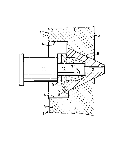
Flgure 1 shows schematically a cross sectlon through an
lnstallation o a plasma generator in the wall of a shaft furnace.
:
~' ',. ' ' : '' , . ' '
,

~l2~; ,'4~;
Fig ure 1 shows a part of a shaft furnace wall, generally
designated 1, having an outer sheet metal casin~ 2 and an
internal lining 3 of refractory material. A recess 4 is
arranged in the shaft furnace wall 1, having an opening 6 to
fit a tuyère 5. The tuyère is water cooled and p~otrudes a
little way beyond the inside of the shaft furnace wall.
An electric field coil 7 is arranged inside the tuyère. The
field coil 7 may be built as a single unit together with the
tuyère 5. This offers the advantaye of joint coolant supply,
and also facilitates assembly and dismantling, etc.
sluice valve 8 is arranged in front of the tuyère 5, having a
valve disc 9, and in front of the sluice valve is a sealing
flange 10.
The figure shows a plasma generator 11 with its nose 12 and
field coil 7 inserted in the tuyère S. The nose of the plasma
generator also includes a down-stream electrode, not shown on
the drawing, which is water-cooled. When the plasma generator
is in its inserted, operating position, the electric field coil
will surround said electrode, thus effecting the desired rota-
tion of the lower base of the arc generated in the plasmagenerator.
The sealing flange 10 of the sluice valve 8 is arranged to seal
against the plasma generator in operating position and during
insertion and withdrawal of the plasma generator. The valve
disc 9 is arranged to seal ~he opening in the flange when the
plasma generator is fully withdrawn.
Great advantages are achieved by the ability to make the nose
of the plasma generator smooth and with minimal diameter. The
valve can be relatively small, thus making it considerably
cheaper and more reliable. Furthermore, it can more easily be
built into the shaft furnace wall, and the recess 4 in the wall
surrounding the opening 5 can be made smaller. Since the valve
can be placed deeper into the shaft furnace wall, the plasma
generator can accordirlgly be inserted further in.

~L2~ 3~ii
According to an alternative embodiment, the nose of the plasma
generator replaces the water-cooling tuyère. In this case it
is vital that the plasma generator can be inserted sufficiently
far into the shaft furnace in order to save the lining and to
achieve satisfactory gas distribution in the shaft furnace,
which is achieved by utilizing the present invention.

Representative Drawing
A single figure which represents the drawing illustrating the invention.
Administrative Status

2024-08-01:As part of the Next Generation Patents (NGP) transition, the Canadian Patents Database (CPD) now contains a more detailed Event History, which replicates the Event Log of our new back-office solution.

Please note that "Inactive:" events refers to events no longer in use in our new back-office solution.

For a clearer understanding of the status of the application/patent presented on this page, the site Disclaimer , as well as the definitions for Patent , Event History , Maintenance Fee  and Payment History  should be consulted.

Event History

Description Date
Inactive: IPC from MCD 2006-03-11
Inactive: Adhoc Request Documented 1993-04-03
Time Limit for Reversal Expired 1992-10-05
Letter Sent 1992-04-03
Grant by Issuance 1990-04-03

Abandonment History

There is no abandonment history.

Owners on Record

Note: Records showing the ownership history in alphabetical order.

Current Owners on Record
SKF STEEL ENGINEERING AB
Past Owners on Record
GUNNAR ASTNER
JAN THORNBLOM
Past Owners that do not appear in the "Owners on Record" listing will appear in other documentation within the application.
Documents

To view selected files, please enter reCAPTCHA code :


To view images, click a link in the Document Description column. To download the documents, select one or more checkboxes in the first column and then click the "Download Selected in PDF format (Zip Archive)" or the "Download Selected as Single PDF" button.

List of published and non-published patent-specific documents on the CPD .

If you have any difficulty accessing content, you can call the Client Service Centre at 1-866-997-1936 or send them an e-mail at CIPO Client Service Centre.


Document
Description 
Date
(yyyy-mm-dd) 
Number of pages   Size of Image (KB) 
Abstract 1993-10-07 1 21
Cover Page 1993-10-07 1 18
Drawings 1993-10-07 1 19
Claims 1993-10-07 3 80
Descriptions 1993-10-07 6 168
Representative drawing 2001-07-04 1 16