Note: Descriptions are shown in the official language in which they were submitted.
~2~S~,3
The present invention relates generally to a picture
frame for framing pictures and, more particularly, it relates
to such a picture frame for the inexpensive framing of
posters or prints and the like so as to present an
aesthetically pleasing and yet very inexpensively framed
picture.
I had previously designed a picture frame which was very
inexpensive and so easy to assemble that any one could do so
with aesthetic and precise results. Basically, the picture
frame of my earlier design comprised side members which
engaged with and held the side edges of a picture and its
protective coverings and elbow-shaped cornerpieces which
engaged the adjacent ends of adjacent side members to mask
and conceal these ends and perpendicularly aligned the side
members. The side members were formed of extruded plastic so
that the ends might be cut to the length required for the
picture to be framed and, because of the concealment thereof
by the cornerpieces, little regard needed be given to the
accuracy or exactness of the end cut of the side members.
Each cornerpiece was adapted to engage with and clamp onto
the adjacent ends of adjacent side members by the exertion of
a downward force on the cornerpiece in a direction
perpendicular to the plane of the picture so that inadvertent
distortion or misalignment of the picture frame and/or the
parts being framed did not occur. This picture frame,
although inexpensive and easy to assemble, was primarily
adapted for the framing of pictures which include
,
~,' , -
front and back protective coverings and supports such as the
picture glass and a semi-stiff or rigid backing,
respectively. Such protective coverings for the picture,
being relatively stiff and unyielding, serve the purpose of
maintaining the picture in a flat or planar attitude. The
frame in such a case merely supports the various elements
constituting the picture, i.e. the picture and its protective
coverings, and holds the same together.
However, there is a certain class of pictures for which
the use of a picture glass or other transparent covering and
a semi-rigid backing is too extravagant in relation to the
picture itself. Such pictures are in the form of posters,
which tend to be relatively large, and prints. Artistic
decor utilizing posters and large prints has come into vogue
in recent years. Where such poster-type pictures are
inexpensive, it is often times not worthwhile to provide the
same with a glass covering and a semi-rigid backing together
with a frame for the entire assembly, since these various
extra elements often cost far in excess of the cost of the
original poster to be framed. Thus, on many occasions, one
sees attractive poster-like pictures which are tacked or
otherwise fastened to a wall for the purpose of exhibiting
the picture and maintaining it flat. Such securement of a
poster-like picture to a wall not only causes damage to the
wall but very often tends to be unsightly in that tacks or
tape or some other objects are utilized in fastening the
picture to the wall.
~Z~
It is, therefore, a primary object of the present
invention to provide a picture frame for a poster-like
picture wherein no support elements or structure are utilized
with the picture other than the picture frame itself, which
is of simple and inexpensive construction.
This object, as well as others which will hereinafter
become apparent, is accomplished in accordance with the
present invention by the provision of a picture frame for
poster-like pictures which includes at least a top picture
edge support, a bottom picture edge support, and fastening
elements which fasten the respective edges of the poster-like
picture to the top and bottom supports. Each picture edge
support includes a flat back plate which extends
substantially the length of the edge of the picture being
framed and a substantially C-shaped portion or member one leg
of which is conne~ted to the outer edge of the back plate
while the other leg extends downwardly toward the flat back
plate to define a gap between the terminus thereof and the
back plate. The picture edge support is preferably formed of
extruded plastic. The fastening elements are also generally
C-shaped and resiliently engage around the generally C-shaped
member of the edge support with the inside leg extending into
the gap between the terminus of the inside leg of the
C-shaped member and the flat back plate so as to press the
edge of the poster-like picture inserted into the gap against
the back plate of the edge support. The invention also
contemplates the provision of edge supports for each side
--3--
" .
lZ6'~
edge of the poster-like picture wherein the fastening
elements are in the form of elbow-shaped cornerpieces which
engage the adjacent ends of adjacent edge supports so as to
secure or fasten the poster-like picture to the flat back
plates of the supports at the corners of the picture.
Other objects and features of the present invention will
become apparent from the following detailed description
considered in connection with the accompanying drawings. It
is to be understood, however, that the drawings are designed
as an illustration only and not as a definition of the limits
of the invention.
In the drawings wherein similar reference characters
denote similar elements throughout the several views:
Fig. 1 is a perspective view of an assembled picture
frame according to the present invention framing a
poster-like picture;
Fig. 2 is an enlarged perspective view in detail of an
edge support and fastening elements of the picture frame of
Fig. l;
Fig. 3 is an enlarged cross-sectional view in
perspective of an edge support and fastening element secured
thereon;
.'.'::` ' :'
r~
Fig. 4 is a perspective view of an assembled picture
frame having four edge supports with a portion of the framed
picture broken away;
Fig. 5 is an enlarged perspective view of a portion of
the picture frame of Fig. 4 as viewed from the rear thereof;
Figs. 6 to 9 show additional constructions for the
picture frame of the present invention.
Fig. 10 is a cross-sectional view of another embodiment
of an edge support of the picture frame together with a wall
fastening device;
Fig. 11 is an exploded view of the embodiment shown in
Fig. 10; and
Fig. 12 is a perspective view of the wall fastening
device of Fig. 10.
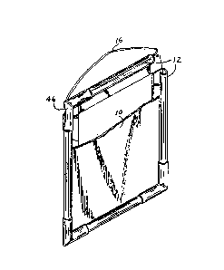
Now turning to the drawings, there is shown in Fig. 1 a
poster-like picture, designated 10, which i5 generally formed
of relatively thin paper material. For the purpose of
maintaining picture 10 flat so that it may be hung from a
wall or similar structure without distortion, the upper edge
and the lower edge of picture 10 are provided with
substantially identical edge supports, designated 12, to
which fastening elements 14 are engaged for securing picture
lZ~
10 to the edge supports. A picture frame hanging wire 16 may
also be provided in connection with the upper edge support
for the p~rpose of hanging the picture.
As clearly seen in Fig. 2, edge support 12 includes a
flat back plate 18 which extends for the length of the edge
support and which has extending upwardly from the plane
defined by back plate 18 a substantially C-shaped member 20
having legs 22 and 24. As clearly seen, outer leg 22 is
connected to the outer edge terminus of back plate 18 and
inner leg 24 extends towards back plate 18 to define a gap 26
between the terminus of leg 24 and back plate 18. Gap 26 is
sufficient to permit the insertion therein of the edge of the
poster-like picture 10, as clearly seen in phantom in
Fig. 3. Fastening element 14 is shown as having a
substantially C-shaped configuration which basically conforms
to the shape of member 20 of edge support 12 but having an
inside diameter slightly smaller than the outside diameter of
member 20 so that a snap fit results when fastening element
14 is engaged with member 20 because of the increased tension
therebetween. The depending legs 28 and 30 of fastening
element 14 are provided at their ends with engagement cams 32
and 34, respectively. As clearly seen in Fig. 3, leg 28 of
fastening element 14 is slightly longer than leg 30 so that
engagement cam 32 engages the corner defined by back plate 18
at its connection to outer leg 22 of C-shaped member 20 while
engagement cam 34 engages the terminus 36 of leg 24 of
C-shaped member 20. The foot of engagement cam 34,
--6--
designated 38, extends into gap 26 below terminus 36 of leg
24 to press or pinion the edge of picture 10 against bac~
plate 18 of support 12, thus fastening or securing picture 10
to edge support 12. As clearly seen in Fig. 2, fastening
element 14 may be provided at one end thereof with a wall 40
so as to present a closed end therefor. Both ends of
fastening element 14 are bevelled at 42 so that when the
fastening elements are applied at the ends of edge supports
12, a very neat and aesthetic appearance is presented, as
clearly seen in Fig. 1. Preferably, edge support 12 is
formed of extruded plastic while fastening element 14 is
formed of injection molded plastic.
In order to provide for picture frame hanging wire 16, a
cut-out 44 is provided at the extreme outer end of engagement
cam 32 of fastening element 14. Picture frame wire 16 is in
the form of a continuous loop which passes through the cavity
of C-shaped member 20 and out the ends thereof. The
respective fastening elements 14 at the ends of support 12
are displaced sufficiently along member 20 to permit wire 16
to exit therefrom and hang relatively straight because of
cut-out 44.
As clearly seen in Fig. 4, it is also possible to
construct a frame for picture 10 which extends entirely
around the picture. Thus, four edge supports 12 are
provided, one for each edge of picture 10, with the adjacent
ends of adjacent edge supports 12 being interconnected by
.,,
~Z6'^~5v~
means of elbow-shaped corner fastening elements 46. Each
corner fastening element 46 is constructed and operates in
the same manner as fastening elements 14 described above.
Thus, in erecting the frame for picture 10, as shown in
Fig. 4, each pair of adjacent edge supports 12 is positioned
at the respective edges of picture 10 and the corner
fastening element 46 is aligned with the ends of the adjacent
edge supports and pushed downwardly to engage therewith and
fasten the edges of picture 10 to the respective back plates
18. As seen in Fig. 5, the lengths of edge supports 12 are
adjusted so that a corner space results at the back side of
the picture frame which permits wire 16 to pass therethrough.
In Figs. 6 to 9, modifications of the picture fastening
devices are shown. Thus, in Fig. 6, the outer leg 28 of
fastening element 14 is provided with a hook 46 at the end
thereof which engages the corner between back plate 18 and
leg 22 of member 20. Leg 30 of fastening element 14
resiliently engages with leg 24 of the C-shaped portion 20 to
be held thereon and the foot 38' extends into and engages
with recess 48 formed in back plate 18 so as to press the
edge of picture 10 therebetween. In Fig. 7, a construction
similar to that shown in Figs. 2 and 3 is shown except that a
hook 50 is provided at the end of leg 28 for engagement with
the bottom of back plate 18 rather than the engagement cam 32
of Fig. 3. Also, bottom plate 18 is provided with an
upwardly extending ramp 52 at its free edge which allows the
poster-type picture 10 to drape thereover away from the wall
when it is hung.
., `:
~ :,
In Fig. 8, it is seen that fastening element 14 and
member 20 of edge support 12 are engaged with each other by
means of engagement ribs and complementary sockets. Thus,
leg 28 of fastening element 14 is provided with a
longitudinal socket 54 into which rib 56 of leg 22 extends.
Leg 30 of fastening element 14 is provided with rib 58 which
extends into socket 60 of leg 24 of member 20. In Fig. 9,
legs 22 and 24 of member 20 are inwardly curved to form
depressions 62 and 64, respectively. Legs 28 and 30 of
fastening element 14 are curved at 66 and 68, respectively,
to complement depressions 62 and 64 so that fastening element
14 engages with portion 20 of edge support 12 in a snap fit.
The foot 70 of leg 30 extends up to back plate 18 so as to
press against a picture therebetween.
Another embodiment of the picture frame according to the
present invention is shown in Figs. 10 to 12. In accordance
with this embodiment, the need for a picture frame hanging
wire is eliminated. As seen in Figs. 10 and 11, an edge
support 112 similar to edge support 12 of Figs. 1 to 9 is
provided having a back plate 118 together with a
substantially C-shaped member 120 extending upwardly from the
plane thereof. C-shaped member 120 has depending outer leg
122 and depending inner leg 124 as well as a connecting
flange 125 which is substantially parallel to legs 122 and
124 and which connects edge support 112 to the outer edge
terminus of back plate 118. Depending inner leg 124 defines
a gap, designated 126, between the terminus thereof and back
~Z67~
plate 118 into which the edge of a poster-like picture is
insertable and which can then be fastened and secured by
means of fastening elements as above described in connection
with ~igs. 1 to 9.
A wall fastening device, designated 172, fastens edge
support 112 to the wall. Wall fastening device 172 is
substantially an inverted T shape wherein bottom flange 174
is fastened to the wall by means of screws or other suitable
means such as adhesive. The vertical flange 176 of device
172 is provided with an expanded end 178 which is received
within elongated socket 180 of edge support 112. The
aperture 182 of socket 180 is formed with a narrowed
resilient gap defined by facing inward projections 184 and
186 located at the terminus of outer leg 122 and the terminus
of back plate 118, respectively. The end 178 of flange 176
is received through the resilient gap defined between
projections 184 and 186 and is thus engaged by socket 180.
The strength of outer depending wall 122 of edge support 112
may be enhanced by providing an interconnec~ing brace,
designated 188, between connecting flange 125 and wall 122.
While several embodiments of the present invention have
been shown and described, it will be obvious that many
changes and modifications may be made thereunto without
departing from the spirit and scope of the invention.
--10--