Language selection

Search

Patent 1268495 Summary

Third-party information liability

Some of the information on this Web page has been provided by external sources. The Government of Canada is not responsible for the accuracy, reliability or currency of the information supplied by external sources. Users wishing to rely upon this information should consult directly with the source of the information. Content provided by external sources is not subject to official languages, privacy and accessibility requirements.

Claims and Abstract availability

Any discrepancies in the text and image of the Claims and Abstract are due to differing posting times. Text of the Claims and Abstract are posted:

  • At the time the application is open to public inspection;
  • At the time of issue of the patent (grant).
(12) Patent: (11) CA 1268495
(21) Application Number: 1268495
(54) English Title: ROTATING DRUM END SEAL
(54) French Title: JOINT D'EXTREMITE POUR TAMBOUR TOURNANT
Status: Expired and beyond the Period of Reversal
Bibliographic Data
(51) International Patent Classification (IPC):
(72) Inventors :
  • KRAWCZYK, PAUL D. (United States of America)
  • BOSSO, ALEXANDER (United States of America)
(73) Owners :
  • COMBUSTION ENGINEERING, INC.
(71) Applicants :
  • COMBUSTION ENGINEERING, INC. (United States of America)
(74) Agent: SMART & BIGGAR LP
(74) Associate agent:
(45) Issued: 1990-05-01
(22) Filed Date: 1986-09-18
Availability of licence: N/A
Dedicated to the Public: N/A
(25) Language of filing: English

Patent Cooperation Treaty (PCT): No

(30) Application Priority Data:
Application No. Country/Territory Date
793,942 (United States of America) 1985-11-01

Abstracts

English Abstract


ROTATING DRUM END SEAL
ABSTRACT OF THE DISCLOSURE
Apparatus for sealing an opening (12) in
the end face (13) of a rotating drum (10),
including a stationary backing plate ( 24 ), annular
seal ring (20), surrounding the opening and
extending in a sealing manner between the backing
plate and the end face, resilient means (30 or 52)
biasing the sealing ring into contact with the end
face, and adjustable means (36 or 56, 58) for
varying the force exerted by the resilient means.


Claims

Note: Claims are shown in the official language in which they were submitted.

-5-
CLAIMS
1. In combination, a drum having a
longitudinal axis, means for rotating the drum
about its longitudinal axis, an end wall on one end
of the drum, opening means in the end wall, a
stationary duct extending into the opening means,
an end seal for sealing the opening means, said end
seal including plate means surrounding the duct and
extending perpendicular thereto, an annular seal
ring surrounding the opening means, and extending
in a sealing manner between the plate means and the
end wall, resilient means biasing the seal ring
into contact with the end wall, and adjustable
means for varying the force with which the
resilient means biases the seal ring into contact
with the end wall.
2. The combination set forth in Claim 2,
including means for preventing rotation of the seal
ring with the drum;
3. The combination set forth in Claim 1,
wherein the resilient means is a plurality of
springs.
4. The combination set forth in Claim 1
wherein the resilient means is a fluid-filled,
donut shaped resilient member.

Description

Note: Descriptions are shown in the official language in which they were submitted.


~ ~;8~gs
ROTATIN& DRUM END SEAL
BACKGROUND OF THE INVENTION
Many industries presently make use of
rotating drums for treating various materials. For
example, at a coal fired steam generating plant,
the ash discharged from a furnace is often treated
in a rotating drum. One probl~m encountered in
such an installation is forming an effective seal
around the stationary inlet duct for the rotating
drum. Existing seals for this application
frequently leak after a short period of operation
due to wear or the inability of the seal to follQw
the rotating surface. If the m~terial being
treated is at a high temperature, as ash may be, it
can add to the problem by causing warpage or uneven
thermal expansion of the various pieces of
equipment. Leaka~e of hot, abrasive material, such
as ash, into the atmosphere, can cause damage to
the other machine parts and also is environmentally
hazardous.
SUMMARY OF THE INVE~TION
In accordance with the invention, a seal
is provided for preventing leakage around the area
adjacent the stationary inlet duct for a rotating
drum which is of low friction material, capable o
: 25 wi~hstanding relatively high temperature, is iong
~'
.: '1~
- ~ ~
, . - , ..
" . ,. ~ ,

--2-
wearing, and self-compensating for seal wear, or
out-of-alignment conditions of the rotating drum.
The seal consists of a stationary ring completely
surrounding the opening in the rotating drum, which
s ring is resiliently biased into contact with the
drum. The orce with which the ring is biased is
adjustable so that a desixed force can initially be
applied and can later be adjusted to compensate for
ring wear, drum wobble, or other factors
influencing the seal effectiveness.
~RIEF DESCRIPTION OF THE DRAWING
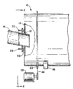
Figure 1 is a partial sectional side view
of a rotary drum;
Figure 2 is a view taken on line 2-2 of
Fig. l;
Figure 3 is an enlarged sectional view of
the end seal o~ the invention; and
Figure 4 is a sectional view of an
alternative end seal of the invention.
DESCRIPTION OF THE PREFERRED EMBODIMENT
Looking now to Figs. 1 and 2 o~ the
drawings, numeral 10 designates a rotary drum
having an opening 12 in the front end 13 thereo~.
Extending into the opçning is a duct 14 by means of
which material to be treated is introduced into the
drum. One such material could be hot ashes from a
coal fired furnace. The drum is driven by a motor
25 through a chain 24 and sprocket assembly 23.
The duct 14 is stationary and does not rotate with
the drum. In order to prevent dust from escaping
from the drum during operation, an end seal 20 is
~ provided which completely surrounds the opening 12.
; The s~al is biased into contact with the front end
13 of the drum by a plurality of members 22, eight
of them being shown in Fig. 2. The members 22 are
equidis~antly spaced around the entire
.
.
: ~ ,
~: ,
, .

~2~ 5
--3--
circumference of the sealing ring, and are
supported by backplate 24 which is secured to the
duct 14.
Looking now to Fig. 3, the end seal will
be explained in more detail. The seal ring 20
completely surrounds the opening 12 in the drum end
13~ The ring is preferably circular, although it
may be of any flguration, the only important
feature being that it completely surround the
opening 12, so as to prevent leakage therefrom.
The ring 20 is fitted in an annular housing 26. A
backing ring 28 is positioned within the housing
also. This ring 28 i5 also circular and extends
through 360 degrees in segments. Positioned 45
degrees apart (Fig. 2) are eight spring biasing
assemblies which force the rin~s 28 and 20 towards
the drum end 13. Each assembly includes a spring
30 which abuts against a plunger 32 at its forward
end and rests on a spring seat at its other end.
The spring force is adjustable by means of bolt 36
which is threaded into the end cap 38. A pin 40,
which extends ~hrough a suitable opening in ring 28
and then also extends into sealing ring 20 a short
distance, prevents the ring 20 from rotating with
~he drum. ~otation of the ring 20 could cause wear
on its sidewalls, or cause it to become twisted or
displaced from the annular housing 26, bxeaking the
seal. A stop surface 42 on plunger 32, when it
contacts surface 44, prevents movement of the seal
to the point where pin 40 would be contactinq end
wall 13. When surfaces 32 and 44 make contactl it
is time to inctall a new sealing ring 20. When the
seal ring has worn some, for example 25-50 percent,
the springs can be readjus~ed so as to exer~ the
same force as they did initially, thus compensating
~or the wear of the ring. This adjustment can be
.
:,
.. .
:~ '
~ ~ .

~ ~8 ~
made during a normal maintenance shutdown, or while
the unit is in operation if desirable.
From the above, it car. be seen that the
seal is simple to initially install, adjust after
wear, or replace. ThP backing ring 28 distributes
the spring loading evenly around the seal ring 20.
rrhe ring 20 can compensate for some wobble or
misa~ignment of the rotating drum. The floating
seal arrangement adjusts the seal to the drum to
compensate for seal wear. Any suitable sealing or
packing ma~erial can be used for the ring 20, For
example, it can be made of graphite, ~eflon'~
asbestos, or even metal.
Figure 4 shows an alternative arrangement
of a seal which eliminates the need for a plurality
of springs. A circular sealing ring S0 is biased
into contact with the drum face 13 by means of an
air filled circular or donut-shaped member 52,
secured to the plate 24. The air pressure can be
varied by connecting connection 54 to a pressure
source 56 through valve 58.

Representative Drawing
A single figure which represents the drawing illustrating the invention.
Administrative Status

2024-08-01:As part of the Next Generation Patents (NGP) transition, the Canadian Patents Database (CPD) now contains a more detailed Event History, which replicates the Event Log of our new back-office solution.

Please note that "Inactive:" events refers to events no longer in use in our new back-office solution.

For a clearer understanding of the status of the application/patent presented on this page, the site Disclaimer , as well as the definitions for Patent , Event History , Maintenance Fee  and Payment History  should be consulted.

Event History

Description Date
Inactive: IPC expired 2022-01-01
Inactive: IPC from MCD 2006-03-11
Inactive: Adhoc Request Documented 1995-05-01
Time Limit for Reversal Expired 1994-11-01
Letter Sent 1994-05-02
Grant by Issuance 1990-05-01

Abandonment History

There is no abandonment history.

Owners on Record

Note: Records showing the ownership history in alphabetical order.

Current Owners on Record
COMBUSTION ENGINEERING, INC.
Past Owners on Record
ALEXANDER BOSSO
PAUL D. KRAWCZYK
Past Owners that do not appear in the "Owners on Record" listing will appear in other documentation within the application.
Documents

To view selected files, please enter reCAPTCHA code :


To view images, click a link in the Document Description column. To download the documents, select one or more checkboxes in the first column and then click the "Download Selected in PDF format (Zip Archive)" or the "Download Selected as Single PDF" button.

List of published and non-published patent-specific documents on the CPD .

If you have any difficulty accessing content, you can call the Client Service Centre at 1-866-997-1936 or send them an e-mail at CIPO Client Service Centre.


Document
Description 
Date
(yyyy-mm-dd) 
Number of pages   Size of Image (KB) 
Cover Page 1993-09-20 1 22
Claims 1993-09-20 1 29
Drawings 1993-09-20 2 55
Abstract 1993-09-20 1 15
Descriptions 1993-09-20 4 148
Representative drawing 2001-08-10 1 10
Fees 1992-03-31 1 26
Fees 1993-03-29 1 22