Note: Descriptions are shown in the official language in which they were submitted.
~x~ s
-- 1 --
INJ~CTION MO~DING NOZZLe HAVING
CIRCUMFERENTIALLY SPACED CONDUCTIV~ PRO~ES
BACKGROUND OF THE INVENTION
l This invention relates generally to in~ection
molding and more particularly to a heated nozzle for
conveying melt from an inlet to a number of spaced gates,
each leading to a different cavity.
Heated noæzles for multi-cavity molding such as
by edge gating are well known in the industry. For
instance, the applicant's U.S. patent number 4,663,S1l
which issued May 12~, 1987 discloses heated nozzles w1th a
variety of different gate con~igurations, one of which is
edge gatin~. While these previous arrangements are
:~ :
:
: :
... . . ..
- ; - : .
..
,. :~ ,
:, ;,,,, : ~: , - . -
.. ... . .
89~L5
., - 2 -
1 entirely satisfactory Eor some applications, in other
cases they do not provide suf:Eicient heat and/or
structural strength or the area adjacent the cavities is
too difficult to cool. As is well known, with the
continual development of more and more difficult to mold
materials it is increasingly important to provide more
heat closer to the gate area. There are various
arrangements to do this for a single central gate, such as
the hop tip seal shown in the applicant's U.S. patent
number 4,450,999 which issued May ~9, 1984 o~ the circular
heating eJ.ement port.ton shown in the applicant's Canadian
patent appllcatlon serial number S78,973 :Elled September
30, 1988 entitled "In~ection Molding Nozzle Having Nose
Portion with Heating Element Encircling the Boee and
Method". However, it is much more difficult to provide
additional heat to the areas of the gate in a
configuration where a number of gates are spaced around or
alon~ the periphery of the nozzle. Also, with some cavity
and gate configurations it is difficult to provide the
mold with sufficient strength to withstand the repeated
impact of the clamp force and the high injection
pressure. In other words, if only a thin portion of the
.~
~ cavity plate is provided between the front end of the
;
~ nozzle and the parting line, the mold will often
. ~
~ 25 eventually fracture resulting in shut down of the
-;
.
~ r .~
~,: : , - . .~ . :. ~
~8~
-- 3
1 system. An early configuration in which a heater cast
having spaced nozzle portions for edge gating is disclosed
in the applicant's u.S. patent number 4,094,447 which
issued June 13, 1978.
SUMMARY OF THE INVENTION
Accordingly, it is an obiect of the present
invention to at least partially overcome the disadvantages
of the prior art by providing a nozzle for a multi-gate
system which is heated by an integral spiral heating
element with a eonfiguration having a plurality of spaeed
heat conductive probes which extend forwardly to conduet
heat adJacent eaeh of the gates.
To this end, in one of its aspects, the
invention provides a heated injection molding nozzle to be
seated in a well in a eavity plate to convey melt from a
nozzle inlet to a plurality of spaced gates extending
through the eavity plate adJacent the nozzle, the nozæle
having a eollar portion adjacent a rear end, and a central
portion having a forward end and a cylindrieal outer
surface extending from the collar portion, the nozzle
having a central melt bore which extends from the inlet at
:
the rear end to the forward end of the central portion,
the nozzle having an electrically insulated heating
.
~ 25 element with a rear end portion and a spiral portion which
.: :..
: .: : - .
,, ~ .
: :
~x~
-- 4
1 is integrally brazed in a channel in the cylindrical outer
surface of the central portion of the nozzle, the rear end
portion of the heating element extending out through the
collar portion to an electrical terminal, the imProvement
wherein the nozzle has an outer sleeve Portion which
encircles the cylindrical outer surface of the central
portion of the nozzle adjacent the forward end of the
central Portion, the sleeve portion having a plurality of
longitudinal conductive probes spaced therearound, the
probes each having a Porward portion which extends a
~redetermined distance forwardl~ oP the Porward end o~ the
central portion o~ the nozzle to provide additional heat
to the melt which flows past the forward Portion to one of
the gates.
Further obiects and advantages oP the invention
will ap~ear Prom the Pollowing description taken together
: with the accompanying drawings.
BRIEF DESCRIPTION OF THE DRAWINGS
.
Figure 1 is a sectional view oP a portion of an
in~ection molding system having a nozzle according to one
embodiment of the invention;
: : :
Figure 2 is an exploded isometric view showing
how the components of the nozzle seen in Figure 1 are
assembled, and
;
~ .
.,, . : . -.
,,, ",:,.. , , .,, , ., , " , . .. ., .. : .
,, ~ , .... . .. .. . . . .
-- 5
1 Figure 3 is another sectional view showing a
nozzle according to another embodiment of the invention.
DETAILED DESCRIPTION OF THE DRAWINGS
_
Reference is first made to Figure l which shows
an injection molding system in which a number of nozzles
10 according to the invention are each seated in a well 12
in a cavity plate 14. Each nozzle has a central portion
16 which extends from a collar portion 18 ~o a forward end
20. An outer sleeve portion 22 encircles the cy:Lindrical
outer sur~ace 24 o~ the centra~ portion 16 adjacent the
forward end 20 o~ the central portion 16. The nozzle 10
is heated by an electrically insulate~theating element 26
which has a rear end portion 28 and a spiral portion 30
which is integrally brazed in a channel in the cylindrical
outer surface 24 of the central portion 16 of the nozzle
10. The rear end portion 28 of the heating element 26
extends out through the collar portion 18 to an electrical
terminal 32. The heating element 26 has a chrome nickel
~ 20 resistance wire 34 extending centr~lly through a
: : refractory powder electrical insulating material 36 such
as magnesiu~ oxide inside a steel casing 3B. ~ :
:~ The nozzle 10 has a number of elongated
conductive probes 40 which are integrally received in the
outer sleeve portion 22, eaoh with a forward portion ~2
:~ :
,, :
~ .
-- , . .. ~ ..
, ~ , . .
-- 6 --
1 which prolect forwardly ~rom the sleeve portion 22 a
predetermined distance into individual sub-wells 4A in the
bottom of the nozzle well 12 in the cavity plate 14. This
configuration provides additional distance between the
forward end 2Q of the central portion 16 and the cavities
46, thus strengthening the mold against the repeated
impact of high in~ection pressure and clamp pressure on
the parting line. In this embodiment, the sleeve portion
22 is made of Hl3 steel and the conductive probes ~0 are
made with a highly conductive copper portion 48 inside an
abrasion and corrosion resistant outer portion 50 made of
hi~h speed steel, A}so in this embodiment, the forward
portions 42 of the conductive probes 40 each have a
pointed tip 52 positioned in one of the sub-wells 44 in
alignment with one of the gates 54 extending through the
cavity plate 14 to a cavity 46. As can be seen, the
conductive Probes 40 extend rearwardly in the sleeve
portion 22 a predetermined distance to pick up heat from
the ad~acent coils 56 of the heating element 26. The
copper portion A8 conducts the heat to the pointed tip 52
~d~acent the gate 54.
The nozzle lO is accurately located in this
position by a circumferential insulating ~lange 58 which
extends from the collar portion 18 and sits against a
circumferential shoulder 60. Also, a seal 62 having a V-
: :
:~
: . . .- . : -: : .:
:;. ~;:.: : - ,
. ~ , , , -, ,
~ . . . . . . .
s
-- 7 --
1 shaped lower surface 64 which sits against a
circumferential flange 66 extending outwardly from the
sleeve portion 22 abuts against the inner surface 68 of
the well 12. Thus, in this PoSition~ an insulative air
space 70 is provided between the hot nozzle 10 and the
surrounding cavity plate 14 with minimum contact between
them. The cavity plate 14 is cooled by pumping cooling
water through conduits 72. As described in the
applicant's U.S. patent number 4,053,271 which issued
October 11, 1977, this seal 62 prevents the pres~urized
melt from fllling the insulative air space 70 during use.
The no~zle 10 has a central melt bore 74 which
extends from an inlet 76 at the rear end 78 to the forward
end 20 of the central portion 16 of the nozzle 10. The
nozzles 10 are secured by bolts 80 to a common elongated
manifold 82 which has a melt passage 84 which branches to
a number of outlets 86, each of which is aligned with the
; melt bore 74 through one of the nozzles 10. The manifold
82 is located securely in place between a back plate 88
and the cavity plate 14 by a central locating ring 90 and
: : a titan~um pressure pad 92. The hack plate 88 is held in
place by bolts 94 which extend through the back plate 88 :
; into the cavity plate 14. The back plate 88 is also
~ :~cooled by pumping cooling water through cooling conduits
: 25 72. The manifold 82 is héated by an electric heating
-: :
'
; ~,. ,. . ~. : ~.
1 element 96 which is cast into it as described in the
applicant's U.S. patent number 4,688,622 which issued
August 25, 1987. The locating ring 90 bridges another
insulative air space 98 between the heated manifold 82 and
the cavity support 14.
In use, the system is assembled as shown in
Figure 1 and electrical power is applied to the terminal
32 of the heating element 26 of each nozzle 10 and to the
heating element 96 in the manifold 82 to heat the nozzles
10 and the manifold 82 to a predetermined operating
temperature. Pressuriæed melt ~rom a molding machlne (not
shown) is in~ected into the melt passage 84 through the
manifold 82 according to a predetermined cycle in a
conventional manner. The pressurized melt flows through
the melt bore 74 in each nozzle 10 into the space 100
adjacent the forward end 20 of the central portion 16 of
the nozzle, from which it flows outward around the forward
portion 42 of each of the conductive probes 40 in the
respective sub-wells 44 and through the gates 54 to ill
the cavities 46. As mentioned above, the inner copper
portion 48 of each of the conductive probes 40 picks up
heat from the ad~acent coils 56 of the heating element 26
and conducts it to the pointed tip 52 adiacent ~the gate 54
to provide sufficient heat for clean efficient gating.
;~ 25 After the cavities 46 are filled, in~ection pressure is
:
9~L5
g
1 held momentarily to pack and then released. After a short
cooling period, the mold is opened along the parting line
102 to eject the molded products. After ejection the mold
is closed and in~ection pressure is reapplied to refill
the cavities 46. This cycle is repeated continuously with
a frequency dependent on the size and shape of the
cavities and the type of material being molded.
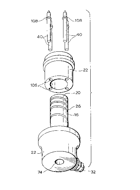
Reference is now made to Figure 2 to describe
how a nozzle 10 according to the invention is made.
Firstly, the heating element 26 ls wound on the central
portion 16, which is then located in the collar portion 22
with the rear end portion 28 of the heating element
extending out to the terminal 32, similar to the method
described in the applicant's U.S. patent numbers 4,7b~,283
which issued September 6, 1988 and A,773,154 which issued
September 27, 1988. The sleeve portion 22 is then placed
over the forward end 20 of the upwardly extending forward
end 20 of the central portion 16. As seen in Figure 1,
the sleeve portion 22 has an inwardly extending flange 104
which sits against the forward end 20 of the central
portion 16 to longitudinally locate it in this position.
A conductive probe 40 is then placed in each spaced
opening 106 in the sleeve portion 22 where periPheral
flanges 108 similarly locate them longitudinally. A
nlckel alloy brazing material is then applied to the outer
~: :
, .
.
... , , -
8~LS
-- 10 --
I surface 24 of the central portion 16 and around the
conductive probes 40 before the assembled are heated in
batches in a vacuum furnace. In this embodiment, as the
furnance is gradually heated to a temperature of
ap~roximately 2000F, the furnance is evacuated to a
relatively high vacuum to remove nearly all the oxygen.
Before the melting Point to the nickel alloy is reached,
the vacuum is reduced by partially backfillin~ the furnace
with an inert gas such as nitrogen. When the nickel alloy
melts, it flows by capillary action around the heating
element 26 to fill the splral channel in the outer ~urEace
24 and integrally embed the heating element 26. The
molten nickel alloy also flows between the central portion
16 and ~he collar portion 18, between the central portion
16 and the sleeve portion 22, and between the sleeve
portion 22 and the conductive probes 40 to integrally bond
them together. Brazing in a vacuum furnace provides a
metallurgical bondin~ of the components which improves the
efficiency of heat transfer Prom the coils 5~ of the
heating element 2~ to the conductive probes 40. After the
~nozzles 10 are cooled and removed from the vacuum furnance
they are machined to remove any excess material such as
the projecting portions of the flanges 108.
RePerence is now made to another embodiment of
the invention as shown in Figure 3~ As most o~ the
, ,
~: :
:
:' : ` ` ' ~"": ~''' :' ,:
i~6B~3~L5
1 elements of this embodiment are identical to those of the
first embodiment, elements common to both embodiments are
described and illustrated using the same reference
numbers. In this embodiment, the forward portion 42 of
the conductive probes 40 have a different shape to provide
for hot edge gating rather than hot tip gating. As can be
seen, the forward end 110 of each probe has a diametrical
channel 112 to convey melt from the space 100 adjacent the
forward end 20 of the central portion 16 of the nozzle 10
to the respective edge gate 114. While a layer of melt
solidifies where it contacts the cooled cavity plate, the
conductive probes 40 provides sufficient heat to the melt
adJacent the forward end 20 and in the channel 112 to
prevent it solidifying. As mentioned above, this
arrangement of having the conductive probes 40 extend a
predetermined distance forwardly into the sub-wells 44
forms the raised central portion 116 of the cavity plate
14 which provides additional strength and allows the
thickness of the cavity plate l~ between the bottom of the
sub-wells 44 and the parting line 102 to ba less for any
given application. This is particularly important for
edge gating low height products. Other than the shape of
the forward ends 20 of the conduc~ive probes 40, the
elements of this embodiment are the same as the first
embodiment and the description of them and their use need
not be repeated.
.,
. . .
~i8:~L~
- l2 -
1 While a descriPtion of the nozzles have been
given with respect to particular embodiments, it is not to
be construed in a limiting sense. Variations and
modifications wi'l occur to those skilled in the art. For
instance, the nozzles can have a different number of
conductive probes 40 for different gate configurations and
the components can be made of other suitable materials
with different shapes and dimensions. Reference is made
to the appended claims for a definition of the invention.
: ~ :
,