Note: Descriptions are shown in the official language in which they were submitted.
` ~Z~ 20
- 1079
BACXGROUND OF THE INVENTION
I _ _
1 1. Field of the Invention
I
¦ This invention relates generally to fluid
¦ pressure oscillators of the type employed to reciprocate
¦ various mechanical devices, and is concerned in particular
¦ to an improved arrangement for controlling the operation of
¦ such oscillators.
2. Description of the Prior Art
I .
1 A typical fluid pressure oscillator is
¦ disclosed in U. S. Patent No. 2,987,051 (Goyette et al).
¦ Here, the reciprocating movement of the piston assembly is
¦ controlled by a relatively complicated valve assembly
located inside the cylinder. In order to gain access to
the valve assembly when performing repair and/or routine
maintenance, the actuator must be almost entirely
dismantled and thereafter reassembled.
Such procedures are extremely time consuming,
and difficult to perform satisfactorily while the
oscillators remain mounted in their "on line" operative
position on production machinery. Consequently, when
repairs or maintenance are required, the oscillators are
normally entirely replaced by spare oscillators that are
either new or that have been subjected to "off line"
repairs and/or reconditioning. Oscillators are relatively
expensive components and therefore the need to maintain an
inventory of spares significantly increases overall
production costs.
240-6T _1_
lZ~Z~
1079
SUMMARY OF THE PRESENT INVENTION
A primary objective of the present invention is
to provide a fluid pressure oscillator with a valve
arrangement which is readily accessible and replaceable
when the need arises, without having to replace the entire
oscillator.
A companion object of the present invention is
the provision of an improved valve arrangement which is
simpler in design and more reliable in operation than those
employed heretofore in prior art arrangements.
These and other objects and advantages of the
present invention will be described hereinafter in greater
detail in connection with a preferred embodiment wherein a
fluid pressure ~scillator is provided with a cylinder
containing a piston assembly. Fluid actuated reciprocation
of the piston assembly is controlled by a valve mounted
externally of the cylinder. The valve is alternately
shifted between "advance~ and "retract" settings by a
reciprocating actuating rod removably received in the
cylinder. A magnet on the piston assembly cooperates with
magnetic elements on the actuating rod to automatically
reciprocate the latter.
The novel features which are considered as
characteristic of thè present invention are set forth in
particular in the appended claims. The invention itself,
however, both as to its construction and operation,
together with additional objects and advantages thereof,
will best be understood from the following description of
240-6T ~ -2-
.. .
. ~ ' .
ZO
~ : l
1079
a preferred embodiment when read in connection with the
accompanying-drawings.
B~IEF DESCRIPTION OF T~E DRAWINGS
Figure 1 is a per.spective view of a fluid pressure
oscillator in accordarlce with the present invention.
Figure 2 is a longitudinal sectional view on a
greatly enlarged scale taken through the fluid pressure
oscillator shown in Figure l;
Figures 3 and 4 are additionally enlarged sectional
views taken respectively along lines 3-3 and 4-4 of Figure 2;
¦ and
Figures 5A and 5B are schematic illustrations
¦ showing the valve assembly adjusted respectively to its
l "advancen and "retract" settings.
¦ DETAILED DESCRIPTION OF DISCLOSED EMBODIMENT
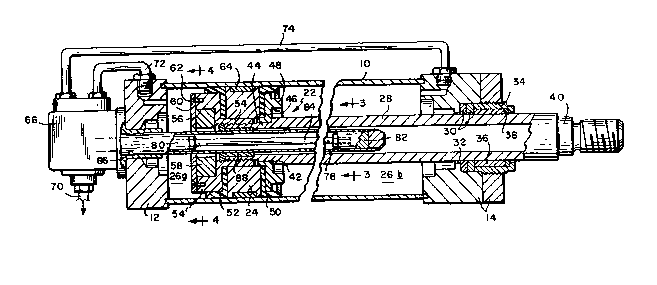
¦ Referring initially to Figures 1-4 of the drawings,
¦ a fluid pressure oscillator in accordance with the present
¦ invention is shown comprising a cylinder 10 having its
¦ opposite ends closed by end caps 12 and 14. The end caps are
¦ held together by tie bolts 16 extending externally of the
¦ cylinder, and the cylinder is pivotably supported as at 18 on
¦ a pair of brackets 20, only one of which is shown in Figure
t.
A piston as~embly 22 is mounted in the cylinder 10.
The piston assembly includes an annular piston 24 which
subdivides the cylinder into chambers ~6a and 26b. A tubular
piston rod 28 protrudes axial~y from the piston ~hrough an
opening in the end cap 14. Sealing rings 30 encircle the
240-6T ~ -3-
lZ6~
1079
piston rod. The sealing rings are held in place against an
interior circular shoulder 32 by means of a bushing 34
threaded into the end cap 14. The bushing 34 contains a
sleeve bearing 36 and .an additional ring seal 38.
S The protruding end of the piston rod 28 is closed by
an externally threaded end plug 40. At its opposite end, the
piston rod has a shoulder 42 leading to a reduced diameter
portion 44 which is threaded externally at its outermost end.
A collar 46 is received on the reduced diameter portion 44
against the shoulder 42. One side of collar 46 has an
integral circular nose 48 protruding axially therefrom, and
the opposite side of the collar locates a circular piston seal
50. The piston 24 is mounted between the seal 50 and a second
mirror image seal 52. A sleeve 54 with an.enlarged diameter
annular head portion 54' i8 threaded onto the piston rod to
hold the collar 46, piston 24 and seals 50, 52 in place.
The head portion 54' defines a circular cavity 56
containing an annular permanent.magnet 58. The magnet is held
: in the cavity 56 by a retainer plate 60 secured to the head
poetion 54' by any convenient means such as machine screws 62.
The piston 24 is externally grooved to contain a slide bearing
: 64 in contact with the interior surface of the cylinder 10.
: A control valve 66 is removably mounted on the end
cap 12. The control valve is adapted for connection to a
: 25 fluid pressure feed line 68 leading from a pump or other
like source of pressurized fluid (not shown), and to a return
or drain line 70. The control valve 66 is additionally
_4_
240-6T
, .
, ,
~IL26~f?2~3
1079
connected by conduits 72, 74 leading respectively to the
cylinder chambers 26a, 26b.
The control valve i5 of the conventional 4-way
type having an internal spool 76 adapted to be shuttled to
and fro between an "advance" setting as shown in Figure 5A
and a "retract" setting as shown in Figure 5B. When in the
advance setting, the spool passages respectively connect
the pressure and return lines 68, 70 to the cylinder
chambers 26a, 26b via conduits 72, 74, causing the piston
assembly 22 to be advanced to the right. When in the
retract setting, the spool achieves the opposite result,
i.e., the pressure and return lines 68, 70 are connected
via conduits 74, 72 to the chambers 26b, 26a, causing the
piston assembly to be retracted in the opposite direction.
The spool 76 is shuttled to and fro by a tubular
actuating rod 78 which protrudes from the valve 66 axially
through the end cap 12 and the magnet 58 into the piston
rod 28. The actuating rod contains axially spaced magnetic
elements 80, 82 interconnected by an internal rod 84. The
actuating rod 78 is guided for slidable movement in
relation to the cylinder end cap 12 by a bushing 86, and
for slidable movement relative to the piston assembly 22 by
means of a second bushing 88 inserted into the end of
piston rod 28.
With the exception of the magnet 58 and the
magnetic elements 80, 82, the remainder of the metallic
components are made from non-magnetic metals such as brass
and chrome plated stainless steel. The various seals and
~4~ 5_
~ ~2~`Z~
1 1079
¦ guide bushings are typically non-metallic, e.g., thermo-
¦ plastic or rubber. The magnetic elements can, for example, be
¦ made from 430F stainless steel.
¦ The oscillator operates in the following manner:
¦ when the control valve spool 76 is set as shown in Figure SA,
¦ pressurized fluid advances the piston assembly 22 to the right
¦ until such time as the attractive force of magnet 58 pulls the
¦ magnetic element 82 of actuating rod 78 to the left. This
¦ causes the spool 76 to be shunted to the position shown in
¦ Figure 5B, with the result that the piston assembly 22 is now
¦ retracted to the left. This motion will continue until the
attractive force of the magnet 58 acts on magnetic element 80
to shunt the actuating rod 78 and spool 76 back to the advance
setting shown in Figure 5A. In other words, each time the
1g actuating rod 78 and spool 76 are shunted in one direction by
the attractive force of the magnet 58 acting on one or the
other of the elements 80, 82, the piston assembly 22 is
reciprocated in the opposite direction. This reciprocating
action will continue as long as pressurized fluid is being fed
to the control valve 66.
In light of the foregoing, it will now be
appreciated by those skilled in the art that the present
invention embodies a number of novel and advantageous
features. For example, the control valve 66 is arranged
entirely externally of the cylinder 10. When repair or
replacement of the control valve is required, one need only
disconnect the pressure and return lines 68, 70 and the
connecting conduits 72, 74. Thereafter, as shown by the
240-6T , -6-
126:3i"'~
¦ 1079
¦ phantom lines in Figure 1. The control valve along with
¦ the actuating rod 78 can be pulled from the cylinder,
¦ without disturbing the piston assembly 22. A fresh control
¦ valve then can be reinstalled by a reverse procedure. This
¦ can be accomplished quickly, while the oscillator remains
¦ installed in an "on line" operative position.
¦ The means for controlling the reciprocation of
¦ the actuating rod 78, and hence the reciprocation of the
¦ piston assembly 22 is relatively simple and trouble free.
¦ It basically entails a single permanent magnet 58 riding
¦ with the piston assembly, and a pair of axially spaced
¦ magnetic elements 80, 82 on the actuating rod 78. The
¦ entire assembly is thus easy to maintain, and relatively
¦ inexpensive as compared to prior art arrangements involving
internal complicated valve arrangements.
1~ 1
~: :
: ~ : ,
~ ~,
'''' ~
2 4~0--6T - 7-
: ',
I