Note: Descriptions are shown in the official language in which they were submitted.
~Z693~
Descri~tion
Lif-t Mast Transport Arrangement
Technical Field
This invention relates generally to a
transport arrangement for a lift mast assembly, and
more particularly, to a transport arrangement for
guiding and driving a lift mast assembly between spaced
apart locations on and longitudinal of a material
handling frame.
Background Art
Material handling vehicles, and particularly
those known as reach trucks, have a lift mast mounted
thereon which is longitudinally movable on the vehicle
between spaced apart locations. Typically, the lif-t
mast assembly .is guided for longitudinal movement by
chains, rollers, and the like engaged with spaced apart
frame side members which extend in a longitudinal
direction relative to the longitudinal axis of the
vehicle. The guide rollers and chains engage the
spaced apart frame side members in a manner so that the
mast is movable along the vehicle axis and to some
degree in directions transverse the vehicl~ axis to
accommodate manufacturing tolerance build up. Often
excessive play in directions transverse the movement of
the lift mast assembly along the frame side members
will permit cocking, skewing and other movements of the
lift mast which are detrimental to the perEormance and
life of the chains, rollers, and a.ssociated
componentry. Representative examples o different ways
of connecting the lift mast assembly to the vehicle for
longitudinal movement along spaced apart frame members
as discussed ~bove are shown in U.S. Patent 2,3~0,601
. - ~ ' - ~ .
- . , ~ - .
~2~935~
to R. C. Howell dated June 1, 1943, U.S. Patent
2,667,985 to H. D~ Woughter da~ed February 2, 1954,
U.5. Patent 2,997,194 to A. E. R. Arnot dated August
22, 1961, and U.S. Patent 3,240,372 to J. E. Joyce
et al. dated ~arch 15, 1966.
In order to move the lift mast assembly along
the spaced apart side members of the vehicle frame, a
suitable drive mechanism must be provided. Heretofore
mentioned U.S. Patent 2,667,985 to ~. D. Woughter dated
February 2, 1954 utiliæes drive chains, sprockets, and
an electric motor to move the lift mast longitudinally
relative to the vehicle, and aEorementioned U.S. Patent
2,320,601 to R. C. Howell dated June 1, 1943 utilizes a
hydraulic jack connected between the vehicle frame and
the lift mast assembly for propelling the lift mast
along the spaced apart side members and longitudinally
relative to the vehicle. Each of these drive
arrangements are complicated, expensive, noisy, req~ire
a substantial amoun-t of space on the vehicle, and do
20 not precisely and smoothly position the lift mast along -
the side frame members.
Screw drives have been utilized to
elevationally move lifting devices. Typically, screw
drives are connected between a fixed member and a
movable member and elevate the movable member in
response to rotation of the screw. Examples of
conventional lifting apparatuses having screw drives
are shown in U.S. Patent 2,663,929 ~o L~ M. Carpenter
dated ~ecember 29, 1953, and U.S. Patent 3,309,060 to
J. Villars dated March 14, 1967. In each oE these
patents, the screw drives are subjected to side loading
forces which are transferred from the load being lifted
to the lifting device and to the screw shaft. As a
result, these side loading forces cause premature wear
and ultimately failure of the screw and associated
~2~3S~:9
screw drive componentry. As a result, screw drive
arrangements for lifting loads have seen only limited
use and limited success.
Because a screw drive is capable of accurately
and precisely positioning the driven element along its
length, it is a desirable way oE moving a lift mast
assembly along the longitudinal vehicle axis. However,
in order to be able to successfully utilize a screw
drive, the problems associated with side loading the
screw drive must be reduced to an acceptable level.
The solution to this problem is complicated even more
due to the fact that a controlled amount of movement of
the lift mast assembly transverse the longitudinal axis
of the vehicle must be provided to accommodate
manufacturing and assembly tolerance stack up, and the
like.
Disclosure of the Invention
In an aspect of the present invention, a
material handling vehicle has a frame having first and
second spaced apart end portions and a longitudinal
vehicle axis extending between the first and second end
portions. A first guide rail is connected to the frame
and substantially parallel to the longitudinal vehicle
axis, and a second guide rail is connected to the ~rame
at a location spaced from the first guide rail and
substantially parallel to the first guide rail. A
transport device connects a lift mast assembly to the
first and second guide rails and guides movement of the
lift mast assembly along the first and second guide
rails in a direction substantially parallel to the
longitudinal vehicle axis, and a power device moves the
transport means along the first and second guide rails
between a ~irst position at which the lift mast
assembly is adjacent the frame first end portion and a
~2693sq:9
-4-
second position at which the lift mast assembly is
spaced from the Eirst position and between the Eirst
and second end portions. A coupling device connects
the power device to the transport device and provides a
preselected amount of free movement of the transport
device relative to the power device in directions
substantially transverse the guide rails.
arief Description of the Drawin~s
Fig. 1 is a partial diagrammatic side
elevational view of a material handling vehicle showing
a lift mast mounted thereon and movable between a Eirst
position as shown in phantom lines, and a second
position as shown in solid lines;
Fig. 2 is a diagrammatic partial sectional
view taken along lines II-II of Fig. 1 showing a
transport means Eor connecting the lift mast assembly
to first and second spaced apart guide rails, a power
means for moving the transport means along the first
and second guide rails, and a coupling means for
connecting the transport means to the power means;
Fig. 3 i5 a partial sectional view taken along
lines III-III of Fig. Z showing the power means, drive
means, and connecting means in substantially greater
detail;
Fig. 4 is a diagrammatic view showing the
power and coupling means in greater detail and at the
first position of the lift mast assembly; and
Fig. 5 is a diagrammatic end view taken along
lines V-V of Fig. 4 showing the power means, coupling
means, and transport means in greater detail, and with
portions broken away for clarity~
il21Ei93S~
--5--
Best Mode For Carryin~_Out The Invention
____
With reference to the drawings, and
particularly Fig. 1, a material handling vehicle 10
which is preferably an AGV (automatic guided vehicle)
has a Erame 12, and first and second spaced apart end
portions 14,16. The vehicle 10 has a longitudinal
vehicle axis 18 and a plurality of ground engaging
wheels 20 which are rotatably connected to the frame 12.
at spaced apart locations thereon.
A first elongated guide rail 22 is connected
to the frame 12 and oriented in a direction
substantially parallel to the longitudinal vehicle axis
18. A second elongated guide rail 24 is connected to
the frame 12 at a location spaced a preselected
distance from the first guide rail 22 and oriented
substantially parallel to the first guide rail 22.
Preferably, the first guide rail 22 has a flange 26,
and the second guide rail has a flange 28. The first
guide rail flange 26 has a side thrust guide surface 30
and first and second spaced apart opposed load carrying
surEaces 32,34 which are connec-ted to the side thrust
guide surface 30. Similarly, the second guide rail
flange 28 has a side thrust guide surface 36 and first
and second spaced apart opposed load carrying surLaces
38,40 connected to the side thrust guide surface 36.
Flanges 26 and 28 project inwardly and towards one
another, and the side thrust guide surface 30 of the
first rail 22 and the side thrust guide surface 36 of
the second rail 24 are parallel to each other, face
each other, and are parallel to the longitudinal
vehicle axis 18.
A lift mast assembly 42 having a pair of
spaced apart elevationally oriented upright guide
members 44,46 and a carriage assembly 48 having a
plarality of forks 49 is provided for lifting a load.
- - . ., ' : .
:
.
~LZ1~93~0
--6-
The carriage assembly 48 is connected to and
elevationally movable along the upri~ht guide members
44,46 between elevationally spaced apart locations on
the elevationally oriented guide members 44,46. The
carriage assembly 48 is driven along the upright guide
members 44,46 in any suitable manner, for example, by a
jack driven chain and sheave arrangement (not shown).
A transport means 50 is provided for
connecting the lift mast assembly 42 to the first and
second spaced aoart guide rails 22 and 24, and for
guiding movement of the lift mast assembly 42 along the
first and second guide rails 22 and 24 in directions
substantially parallel to the longitudinal veh.icle axis
18. The transport means 50 engages the side thrust
guide surfaces 30,36 and limits, to a preselected
amount, the amount of transverse movement relative to
the longitudinal vehicle axis 18. Preferably, the
transport means 50 includes a transport frame 52 which
has first and second spaced apart side portions 54 and
56. A first side thrust roller 58 is rotatably
connected to the first side portion 54 and rollingly
engagable with side thrust guide surface 30.
Similarly, a second side thrust roller 60 is rotatably
connected to the second side portion 56 and rollingly
engageable with the side thrust guide surface 36 of the
second guide rail 28. It is to be noted that although
only one side thrust roller 58,60 has been discussed
with respect to each~of the first and second guide
rails 22,24~ respectively, additional side thrust
rollers 58',60' may be utilized to reduce the amount of
transverse and cocking motion of the transport frame 52.
A first pair of load rollers 62 is rotatably
connected to the first side portion 54 at elevationally
spaced apart locations on the first side portion 54.
One load roller 64 of thc fiest pair of~load rolleFs 62
- , : . ... .
'
'
' , . .
' ' . ' .. ..
'
~26~3~
--7--
is engageable with the first load carrying surface 32
of first guide rail 22, and the other load roller 66 of
the first pair o~ load rollers 62 is enga~eable with
the second load carrying surface 34 o:E :Eir~st guide rail
22. Similarly, a second pair of load rollers 68 is
rotatably connected to the second side portion 56 of
transport frame 52 at elevationally spaced apart
locations on the second side portion 56~ One load
roller 70 of the second pair of load rollers 68 is
engageable with the second guide rail first load
carrying surface 38, and the other load roller 72 of
the second pair oE load rollers 68 is engageable with
the second guide rail 24 second load carrying surface
40. Although only one pair of load rollers 62,68 has
been discussed with respect to each of the first and
second side portions 54,56 and first and second guide
rails 22,~4, additional pairs of first and second pairs
of load rollers 62',68' may be provided on t~e first
and second side portions 54,56, respectively. Each
pair of -the pairs of load rollers 62,62',68,68'
heretofore discussed are rollingly en~ageable with
respect to an adjacent one of flanges 26,28.
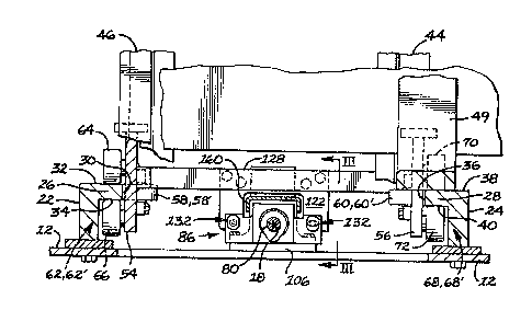
As best seen in F.igs. 3 and 4, power means 74
is provided for moving the transport means 50 along the
first and second guide rails 22 and 24 between a first
position 76 at which the li:~t mast assembly 42 is
adjacent -the frame ~irst end portion 14, and a second
posi~ion 78 at which the lift mast assembly 42 is
spaced from the first position 76 and between the first
and second end portions 14 and 16. The power means 74
has a shaft 80 which is positioned between the first
and second guide rails 22 and 24, and connected to the
frame 12. Shaft 80 extends in a direction
substantially parallel to the longitudinal vehicle axis
18. The power means 74 also includes a motor 82 having
~Z693~;~
-8~
an output mernber 84 which is drivingly connected to ~he
coupling means 86. The coupling means 86 is mounted on
the shaft 80 and movable along the shaft 80 .in response
to movement of output member 84. It is to be noted
that the coupling means 86 is guided by the shaft 80
for movement therealong and that the output member 84
drives the coupling means 86 in any suitable fashion.
Specifically, the output member 84 is
rotatable and connected to the shaft 80 .in any suitable
manner, such as by a cog belt 88 which is trained about
a first sheave 90 mounted on the output member 84, and
a second sheave 92 mounted on a second end portion 94
of shaft 80. The shaft 80 also has a first end portion
96 which is spaced from the second end portion 94, an
outer cylindrical surface 98, and a hel.ical annular
groove 100 disposed in and along the outer cylindrical
surface 98.
A first bearing carrier 102, having a bore 104
disposed therein, is connected to the frame 12 at a
location adjacent the first end portion 14 of the
vehicle frame 12. A second bearing carrier 106, having
a bore 108 disposed therein, is connected to the frame
12 at a location spaced from the first bearing carrier
102 and closely adjacent the second position 78 of the
lift mast assembly 42. A first bearing 110 which has a
bore 112 is mounted in the first bearing carrier bore
104, and a second bearing 114 having a bore 116
disposed therein, is mounted in the second bearing
carrier bore I08. The first and second bearings 110
and 114 are preferably anti-friction bearings of a
conventional design. The shaft first end portion 96 is
disposed in the first bearing bore 112, and the shaft
second end portion 94 is disposed in the second bearing
bore 116. Preferably, shaft 80 is rotatable relative
3s to the first and second bearing carriers 102 and 106,
. .
. . ~ . .
- .: - .
" :~21693~;~
_g_
and lies along the longitudinal vehicle axis 18. A
plurality of seals 118 are connected to the first and
second bearing carriers 102 and 106, and sealingly
engaged with the shaft 80 to prevent contamination o.E
the bearings 110,114 and the leakage of lubricant from
the bearings 110,114.
The coupling means 86 connects the power means
74 to the transport means 50 and provide a preselected
amount of free movement of the transport means 50
relative to the power means 74 in directions transverse
the irst and second guide rails 22,24. The coupling
means 86 inclùdes a guiding portion 120 and a
connecting portion 122. The guiding portion has a
drive portion 124 and a flange portion 126 which is
connected to the drive portion 124. The drive portion
124 is mounted on shaft 80, disposed in the helical
groove, and movable along the shaft in response to
rotation oE the shaft 80. The connecting portion 122
is mounted on the transport means 50 and connected to
the flange portion 126 of the guiding portion L20. The
connecting portion 122 moves transport means 50 along
the guide rails 22 and 24 in response to movement of
the guiding portion 120 along the shaft 80. The
connecting portion 122 is movable relative to flange
portion 126 in directions transverse the guide rails 22
and 24, but fixed relative to the flange portion 126 in
the remaining directions. The conn~cting portion 122
is preferably secured to a cross member 128 which is
connected to the first and second side portions 54 and
56 of the transport frame 52 by a plurality of
fasteners 130. The connecting portion 122 has a pair
of spaced apart ears which extend from a body portion
and straddle the shaft 80 or clearance purposes. ~ :
Preferably, a fastening means 132 attaches the
connecting portion 122 to the flange por-tion 126 and - `
maintains the connecting portion 122 for slidable
movement relative to the flange portion 126 in
- ,
. - . : :.: . .
~2~3Si~
--10--
directions transverse the first and second yuide rails
22 and 24. The connecting portion 122 is movable along
the shaEt ~30 with and .in response to movement of the
guiding portion 120 along the shaft 80 and between
spaced apart locations on the s'naft 80 in response to
movement of the output member 84.
The guiding portion 120 has a spherical ball
134 connected to the drive portion 124 and a spherical
seat 136 connected to the flange portion 126. The
spherical seat 136 is matingly engaged with the
spherical ball 134. The spherical ball 134 and
spherical seat 136 permits pivotal movement of the
drive portion 124 relative to the flange portion 126 in
order to accommodate a preselected amount of cocking
and skewing movement of the transport means 50 relative
to the shaft 80.
The coupling means 86 has a plurality of
sphericaI balls 138 which are disposed between the
drive portion 124 and the shaft 80 and in helical
groove 100~ The balls 138 are forced to move along the
helical groove in response to rotation of the shaft
80. Thus, rotary motion of the shaft 80 is converted
to linear motion of the coupling means 86. The balls
138 provide a substantially friction free connection
between the shaft 80 and drive port:ion 124.
A retainer 140 which is screwthreadably
connected to the drive po.rtion 124 connects the
spherical ball 134 to the drive portion 124. A
threaded fastener 142 which is connected to the drive
portion 124 prevents rotation of the retainer 140
relative to the drive portion and locks the retainer
140 at the desired location.
The fastening means 132 includes ~irst and
second transversely spaced apart apertures 144,146
which are disposed in the f].ange portion 126r first and
' , ' ~ ', ,' ~ ",' ~
26~3SO
second transversely spaced apart apertures 145,147
which are disposed in the connecting portion 122, a
Eirst fastener 148 disposed in the first apertures
144,145 of the Elange and connecting portions 126,122,
and a second fastener 150 disposed in the second
apertures 146~147 of the flange and connecting portions
126,122. The Eirst Eastener 148 is free to move a
preselected distance relative to one of the first
apertures 144,145 in the aforemen-tioned transverse
directions relative to longitudinal axis 18, and the
second fastener 150 is free to move a preselected
distance relative to one of the second apeetures
146,147 also in the transverse directions. Pre~erably,
the first and second connecting portion apertures
145,147 are tapped holes, and the first and second
fasteners 148 and 150 are screwthreadably engayed in
the first and second connecting portion apertures
145rl47, respectively. The eirst aperture 144 in the
flange portion 126 is preferably an elongated slot
which is oriented in the direction transverse the first
and second guide rails 22,24, and the second aperture
146 in the flange portion 126 is a cylindrical bore
having a diameter of a preselected magnitude. The
Eirst and second fasteners 148 and 150 each have a
cylindrical shank 152 having a diameter of a
preselected magnitude. The diameter of the cylindrical
shank 152 of the second fastener 150 is smaller in
magnitude than the diameter of the cylindrical bore of
the second flange portion aperture 146. The clamping
force o the first and second fasteners 148,150 is
limited so that the first and second fasteners 148,150
can freely move in the first and second flange portion
apertures 144,146 and thereby permit a preselected
amount o freedom o movement of the connecting portion
122 transverse the first and second guide rails 22,24.
: ;
.. . . . . . . . . .
. ' . : - ~
.. : .
~6~35~
-12-
A lock nut 154 is connected to the threaded por~ion of
each of the first and second fasteners 148,150 and
prevents inadvertent rotation of the Eirst and second
fasteners 14~,150 and loosening thereoE. It is to be
noted that the first and second fasteners extend in a
direction substantially parallel to the side thrust
guide surfaces 30,36 and the longitudinal axis 18.
Likewise, the first and second apertures
144,145,:L46,147 extend through ~he flange and
connecting portions 122,126 in directions substantially
parallel to the firs-t and second side thrust guide
surfaces 30,36 and the longitudinal axis 18.
A first stop 156 is connected to frame 12 at a
location adjacent the frame first end portion 14, and a
second stop 158 is connected to the frame 12 at a
location between the first and second frame end
portions 14 and 16. Preferably, the first and second
stops 156 and 158 are mounted on a shield 160 which
overlies shaft 80 and is connected to the irst and
second bearing carriers 102 and 106. The first stop
156 is screwthreadably adjustable -Eor precisely
defining the Eirst position 76 of the lift mast
assembly 42, and the second stop 158 is shim adjustable
for defining the second position 78 of the lift mast
assembly 42. The first and second stops 156 and 158
engage the connecting portion 122 at the first and
second positions 76 and 78 of the li~t mast assembly
42, respectively. The second stop 158 has an
elastomeric portion 162 which noiselessly and softly
engages connecting portion 122.
Industrial Applicability
With reference to the drawings, and in
operation, the material handling vehicle 10 is adapted
to engage a load to 'oe transported, lift the load being
:
.- ~ ', ' , ' '
~Z6~3S~
-13-
transported onto the materlal handling vehicle 10,
transport the load to the desiced location, and unload
the material handling vehicle 10 at the desired
location. In order to engage the load to be llfted,
the lift mast assembly 42 must move from the second
position 78 to the Eirst position 76 in order to
position the load engaging forks 49 beneath the load
for engagement. The transport means 50 smoothly and
freely guides the lift mast assembly along the first
and second guide rails 22,24 from the second position
78 to the Eirst position 76 at which the first stop 156
engages the connecting portion 122 and prevents further
movement. The side thrust and load carrying rollers
58,58',60,60',62,62',68,68' ensure this ~ree, smooth
movement.
Upon engagement between the forks 49 and the
load to be lifted, the carriage is elevationally moved
on the uprights 44,46 so that the carriage 48 is above
the firs-t and second guide rails 22 and 24. The
transport means 50 and the load and side thrust rollers
68,68',62,62',58,58',60,60' limit the amount o motion
of the lift mast in directions transverse and resist
cocking, twistingl and the like. The power means 74 is
then actuated to rotate shaft 80 and drive the coupling
means 86 along the shaft 80 towards the second position
78 of the lift mast assembly 42. Any movement of the
transport means S0 in directions transverse the guide
rails 22,24 is accommodated by the fastening means 132
and the relative movement between the connecting
portion 122 and guiding portion 120. Thus, any side
loads placed on the lift mast 42 which tend to move the
transpor~ me-ans 50 transverse of the guide rails are
accomrnodated by the coupling means 86. Therefore,
shaft 80 is substantially free of side loadlngs
transferred from the mast 42 through the transport
- ' ~ , ,, ~, ,, ~
- , ' : ~ -.: ~ . - -
:
12~93~j~
-14-
means 50. It should be recognized that manuEactllring
tolerances dictate the necessity for a preselected
amount of free movement of the transport means ln
directions transverse of the guide rails 22,24. As a
result, the coupling means alleviates the problems that
this freedom of movement creates.
The spherical ball 134 and spherical seat 136
accommodates movement of the transport means 50 in a
substantial number oE other directions caused by the
lift mast 42 loading and clearance due to manufacturing
tolerance stack up between assembled parts. This will
further improve the smoothness of operation and extend
the life of the componelnt parts of the power, coupling,
and transport means 74, 86, and 50.
Upon completed retraction of the lift mast 42
to the second position 78 at which the stop 158 engages
connecting portion 122, the load ls then ready to be
transported to a deposit or unloading station wherein
once again the lift mast assembly 42 will be moved from
the second position 78 to -the first position 76. The
power means 74 and particularly the helical drive shaft
80 provide smooth and precise movement and placement of
the lift mast assembly 42 between the Eirst and second
positions 76,78. The coupling means 86 and transport
means 50 enable the preferred helical drive shaft 80 to
be sucessfully used.
Other aspects, objects, and advantages of this
invention can be obtained from a study of the drawings,
the disclosure, and the appended claims.
-: . . ., :
.