Note: Descriptions are shown in the official language in which they were submitted.
~ 4~ 7
The present invention relates to a device for detecting
state of approach of an object such as an obstacle.
Heretofore, a device for detecting an ob;ect which is
used, for example, as an obstacle detecting device for detecting
an obstacle duri~g running of an automobile comprises a transmit-
ter for transmitting an electromagnetic wave or a ultrasonic wave
having directivity and a ~eceiver for receiving the wave which
has been reflected from the ob;ect, thereby detecting the ob;ect,
such as obstacle.
Such a conventional device requires the use of the
transmitter and the receiver, so that it ls complicated in
construc-tion. Furthermore it employes a wave having directivity,
so that it tends to provide an insensible area at close ,range.
The present invention eliminates the disadvantages of
the conventional device and provides a device for detecting an
approaching ob~ect, such as obstacle, in reliable manner, which
has a simple construction.
According to the present invention there is provided a
device ~or detecting an ob~ect, comprising: a first means for
converting a variation of a floating capacity between a sensor
consisting of an electrode plate and an object to be detected
into a variation oE a frequerlcy signal; a second means for
converting said frequency signal into a voltase signal; a third
means including ~irst and second amplifiers arranged so that said
voltage signal is supplied to both first and second amplifiers
which then produce a first amplified signal and a second ampli-
fied signal with a delay, respectively; and a fourth means for
comparing said first and second amplified signals and d~tecting
the state of approach of the object in accordance with the
attenuation of said voltage signal. Thus, the device according
to the present inYention provides a superior advantage in that
the state of approach of an ob~ect can be detected in reliable
..~ ~,
~ 4~'7
manner by the simple construction. Suitably the device which
includes an oscillator for generating a signal having a fixed
frequency; two serially connected networks arranged at -the output
side of said oscillator; a band-pass filter and amplifier for ef-
fecting filtering-off of noise and amplification of the
frequency signals fed from said networks; a detector for
detecting the amplified frequency signal; and a voltage
fluctuation detection circuit for detecting state of approach of
the object in accordance with the attenuation of the voltage
signal from said detector. Preferably a device in which said
voltage fluctuation detection circuit includes: a first amplifier
for amplifying an input voltage signal; a second amplifier having
the same gain as that of the first amplifier for amplifying the
input voltage signal with a fixed delay time; a voltage
comparator for comparing the respective amplified outpu-t ~oltages
to produce a high level output at the time of lowering of the
input voltage signal; and a decision circuit for giving a
decision on whether the time width of the high level output of
the voltage comparator is wider than a predetermined width or
not, thereby detecting the state of approach of the ob~ect to
said sensor.
The present invention also provides a method for
detecting an ob~ect comprising the steps of: converting a
variation of a floating capacity between a sensor consisting of
an electrode plate and an ob~ect to be detected into a variation
of a frequency signal; converting said frequency signal into a
voltage signal; supplying said voltage signal to a first ampli-
fier and, after a delay, to a second amplifier which produces a
first amplified signal and a second amplified signal with said
delay, respectively; and comparing said first and second ampli-
fied slgnals to detect the sta-te of approach of the ob;ect in
accordance with the attenuation of said voltage signal.
~ ~ ~ 9 ~7
Now, the lnvention will be further described with
reference to the accompanying drawings, in which:
Fig. 1 is a sircuit diagram showing the principle of
the detection of ob~ect according to one embodiment of the
present invention;
~;
Fig. 2 iS a block diagram showing an embodiment of the
device according to the present invention;
:lu Fig. 3 is a block diagram showing an example of the
construction of the voltage fluctuation detecting circuit shown
in Fig. 2;
Fig. 4 is a time chart showing the signals in the
1~ voltage fluctuation detecting circuit, shown in Fig. 3; and
Fig. 5 is a circuit diagram showing an example of the
detailed construction of the voltage fluctuation detecting
circuit.
2~
3~ -.
3~
-- 3 --
1~~9~7
--4--
Fig. 1 is a circuit diagram showing the principle
of de-tection of an object according to -the present
invention. In the circuit as shown in Fig. 1, when a
high frequency signal is applied to a series circuit
including an electrode plate 1 and a resistor R, the
floating capacity C between -the electrode' plate 1 and
the objec-t 2 varies in accordance with the distance
-therebetween and the high frequency outpu-t voltage at
the potential dividing point varies accordingly. The
present invention takes advantage of this phenomenon and
-the elec-trode pla-te 1 is u-tilized as a sensor. The
state of approach of -the object 2 can be detected by
detecting the s-tate of lowering of the output voltage
which is caused by the approach of the object 2 to said
sensor .
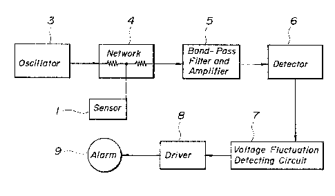
Fig. 2 illus-trates an embodiment of -the device for
detecting an object which is constructed on the princi-
ple of the present invention as explained above. The
device as illustrated in Fig. 2 includes an oscillator 3
for genera-ting a fixed frequency signal, a network ~
consisting of a resis-tance dividing circuit arranged at
the output side of said oscillator 3, a sensor 1 consis-
ting of an elec-trode plate connected to the dividing
point of said network, a band-pass filter and amplifier
6 for effec-ting filtering-off and amplification of the
~ '7
high-frequency output signal produced by said network 4, a
detector 6 for effecting detection of the amplified output
signal, and a voltage fluctuation detecting circuit 7 for
detecting the approach of the ob;ect by detecting the state of
lowering of the detected voltage signal and feedin~ an alarm
command to a driver 8 of an alarm 9.
In the construction as explained above, when a high-
frequency signal having a fi~ed frequency Fo is fed Erom the
oscillator 3 to the network 4, a high-frequency output signal
which has been attenuated in proportion to the degree of approach
u of the object to the sensor 1 is fed to the band-pass filter and
amplifier 5, where the noise induced into -the sensor 1 and the
like is filtered off and only the high-frequency component having
frequency Fo is amplified. The frequency signal which has been
amplified to a predetermined level is sub~ected to detection of
1~ the detector 5 and the D.C. voltage signal corresponding to the
amplitude of said input frequency signal is fed to the voltage
fluctuation detecting circuit 7. This voltage fluctuation
detecting circuit 7 serves to detect the state of lowering of the
D.C. voltage signal applied thereto and apply an alarm command to
2U the driver 8
~!~
3U .
-- 5
~ ~ ~g~'7
Thus, the alarm 9 produces an alarm signal, such as warning sound
or warning light.
Fig. 3 illustra-tes an example of construction of the
voltage fluctuation detecting circuit 7. This circuit includes a
first amplifier 61 for amplifying the output voltage Vo of the
detector 6, a second amplifier 62 for amplifying the same output
voltage Vo with a predetermined delay, a comparator 63 for
comparing the amplified output voltages Vl and V2, and a decision
circuit 64 for giving a decision on whether the time width of the
comparator output signal S is wider than a predetermined width or
not. The amplifiers 61 and 62 have a same gain. The comparator
63 is applied with an offset voltage which is so ad~usted that it
produces a low level output when Vl > V2 and a high level output
when Vl < V20
l';
In the construction as described above, when the input
voltage Vo is lowered during the period T the output voltage Vl
of the amplifier 61 is also lowered during the same period, as
shown in Fig. 4. The output voltage V2 of the amplifier 62 is
lowered, with a flxed delay time Td, with the result that Vl < V2
'' during the
7~
3U
3~
-- 6 --
~ 7
period T + Td and consequently the output S of the comparator 63
has a high level. The period of lowering of the input voltage Vo
varies, depending on the degree of approach of the object 2 to
said sensor 1, and consequently the decision circuit 64 gives an
alarm command when the time width of the output S of the
comparator becomes wider than a predetermined value.
~;
In this regard it is to be noted that Vl = v2 when the
lnput voltage Vo has become fixed, without variation of the
position of the ob~ect 2 rela-tive to the sensor 1, while Vl > V2
when the ob-Ject 2 moves away from the sensor 1, and in each of
these cases the output of the comparator 63 becomes of low level,
so that no alarm command is produced thereby.
Fig. 5 illustrates an example of the detailed
1~ construction in which the each portion of the amplifiers 61 and
62 consists of an operational amplifier. The operational
amplifier OP2 includes a delay element Cd connected in parallel
with a feedback resistor. In this circuit construction, an
offset voltage of the voltage comparator 63 is omitted by
2U properly selecting the offset voltages of the respective
operational amplifiers OPl and OP2.
The device for detecting an ob~ect according to the
~;
3U
3~
-- 7
9~7
present invention has a simple construction, as a whole, so that
it provides little trouble. It has no insensible area at close
range, as in the conventional device, and provides better
detecting state as ob;ect approaches to the device. It can
detect the approaching object only and produce an optimum alarm.
Accordingly it is advantageous to detect an object when an
automobile is moving backward, for example.
:l.u
1';
2~)
~;
3U .
-- 8 --