Note: Descriptions are shown in the official language in which they were submitted.
-1- RCA 83,370
A SYNC SEPARATOR WITH PERIODIC UPDATING
The invention relates to circuits for separating
synchronization signals from a composite video signal.
In a -television receiver, an incoming NTSC
-television signal is coupled via IF stages to a video
detector tha-t generates a corresponding NTSC baseband
composite video signal. In order to separate the
hori20ntal and vertical sync signals from the composite
video signal, a voltage level that is sometimes referred to
as the slice, or slicing level signal is established.
Typically, the slicing level signal is established at a
level that is between the expected level of the tip
portion, or peak, of a given sync pulse and the back porch
portion of the associated blanking pedestal. When the
magnitude of the composite video signal, for example,
exceeds that of the slicing level signal, such as during
the occurrence of the tip portion of the given sync pulse,
an output signal that is the separated sync signal is
generated. On the other hand, when the magnitude of the
composite video signal is lower than that of the slicing
level signal, such as, for example, during an active video
portion of a given video line signal of the composite video
signal, such output signal is not generated.
Typically, the signal gain of the IF stages that
~5 provide the input signal to the video detector is
controlled in an automatic gain control (AGC) loop using
feedback. In order to obtain noise immunity the slicing
level is established at, for example, the mid-range level
that is between the expected levels of the tip and the back
porch portions, respectively. In some prior art circuits
the AGC loop tends to maintain the level of the tip or the
back porch portions at a substantially constant
predetermined level, provided some conditions are met. The
first of such conditions may be that the amplitude of the
incoming television signal remains within the regulating
range of the AGC loop. The second of such conditions may
be that transient variations in the levels o~ the sync tip
and back porch portions that occur from one sync pulse to
-2- RCA 83,370
the next one are small such that the AGC loop, which
normally has a slow transient response time, can track such
changes. Transien-t variations in the composite video signal
may occur, ~or example, when a television receiver is tuned
to a different television channel. Such transient
variations may also occur as a result of, for example,
airplane induced flutter in the incoming television signal
or as a result of other types of external noise signals
accompanying the incoming television signal.
In some prior art circuits, the slicing level is
updated only during the occurrence of the sync pulse by,
for example, peak-detecting the composite video signal to
obtain the peak voltage of the composite video signal at
the proper polarity. Peak detecting may be accomplished by
charging a capacitor to, for example, the level of the tip
portion of -the sync pulse. Updating of the voltage across
the capacitor occurs provided, for example, the level of
the tip portion of the sync pulse is larger than the
voltage across the capacitor at the time the sync pulse
occurs. On the other hand, if the level of the tip portion
of the sync pulse is lower than the voltage across the
capacitor, at the time the sync pulse occurs, the voltage
across the capacitor is no-t affected by the newly received
sync pulse. After the voltage across the capacitor is
updated, the capacitor is discharged at a rate that is
substan-tially smaller than the charging rate that occurred,
as described before, during the occurrence of the
corresponding sync pulse. In this way the voltage across
the capacitor dynamically tracks variations in the
amplitude of the sync pulses, thus causing the slicing
level to do the same.
Whether a given sync pulse causes the updating of
the slicing level is affected, in such prior art
arrangement, by the voltage across the capacitor at the
time the sync pulse occurs. The voltage across the
capacitor that decreases in the interval between sync
pulses is determined by the amplitude of a preceding sync
~2~S~
-3~ RCA 83,370
pulse that causes the charging of the capacitor, as well as
by the discha~ge rate of the capacitor.
It may be desirable to update the slicing level
after a predetermined interval has elapsed without updating
the slicing level such that at the end of the predetermined
interval -the slicing level is unconditionally updated. In
this way the slicing level is updated independently of the
slicing level that has existed prior to -the end time of the
predetermined interval.
In carrying out an aspect of the invention, a
first signal is generated when a given pulse occurs in an
incoming composite video signal that is similar in
characteristic to a sync pulse of the composite video
signal. The first signal is indicative of a given level of
the pulse. A second signal is updated upon generation of
an update control signal to contain information of the
level of the pulse. The update control signal is generated
in accordance with different values of given levels of at
least two occurring ones of the pulses. The update control
signal is generated~at an instant that corresponds with the
occurrence of the given pulse. A timer responsive to said
update control signal generates a time-out control signal,
provided a predetermined interval has elapsed from a -time
when the second signal has been updated. The second signal
is updated upon the occurrence of -the time-out control
signal. The composite video signal and the second signal
are used for generating an output signal that contains
synchronization information.
In accordance with another aspect of the
invention, the update control signal is generated when the
level of the pulse has an amplitude is larger than that of
the last pulse that caused the second signal -to be upda-ted.
In accordance with a further aspect of the invention,
the time-out control signal causes the second signal to be
updated to contain information of most extreme amplitude of
the given level that occurs during the predetermined
in-terval.
-4- RCA 83,370
In accordance with a further yet aspect of the
invention, the predetermined interval that is associated
with the time-out signal has a duration that is independent
of an amplitude of the video signal.
FIGURE 1 illustrates a sync separator in
accordance with an illustrative embodiment of the
invention;
FIGURES 2a-2b illustrate waveforms related to the
trailing edge oE a sync pulse that are useful in explaining
sync pattern recognition operation of the sync separator of
FIGURE 1; and
FIGURES 3a-3c illustrate waveforms useful in
explaining the operation of the sync separator of FIGURE 1
immediately after a sync pattern is recognized.
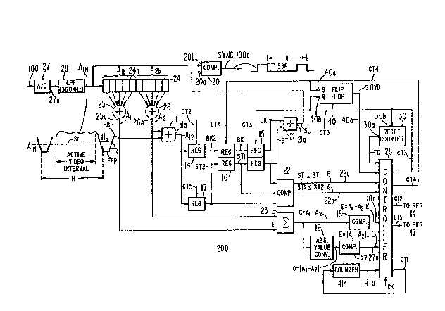
FIGURE 1 illustrates a sync separator 200
embodying an aspect of the invention. An analog, baseband
composite video signal 100 such as, for example, defined in
an NTSC standard, is obtained at an output terminal of, for
example, a video detector of a television receiver, not
shown in FIGURE 1. Analog signal 100 is sampled and then
converted to a digital word in an analog-to-digi-tal
converter 27 at a ra-te 1/T that meets the Nyquist sampling
criteria, where T is the interval between successive
sampling cycles. The rate 1/T is e~ual, illustra-tively, to
14.32 ~Hz, four times the color subcarrier frequency of an
NTSC signal. The digitized signal is low-pass filtered in a
digital low-pass filter 28 to generate a signal AIN. Signal
AIN is coupled to an input port IN of a shift register 24.
Associated with the trailing edge of a given sync
pulse Hs of signal AIN is a flat portion FFP that
corresponds with the tip portion of sync pulse Hs, a
transition portion TR and a flat portion FBP that
corresponds with the back porch portion of th~ associated
blanking pedesatal. Portion FFP is, illustratively, at a
value that is lower, or less positive, than that of portion
FBP.
Sync separator 200 stores values representative
of portions FFP and FBP, respectively, associated with a
-5- RCA 83,370
given sync pulse Hs to provide, in a manner to be described
later, a sync tip signal ST and a back porch signal BK,
respectively, -that are coupled to corresponding input ports
of a summer 21. A slice level signal SL that is produced
at an output terminal 21a of summer 21 contains the average
value of signals ST and BK. Slice level signal SL having a
value that is, illustratively, in the mid-range between the
levels of tip portion FFP and the back porch portion FBP
associated with sync pulse Hs is coupled to an input
terminal 20a of a digital comparator 20. Signal AIN is
coupled to an input terminal 20b of comparator 20.
Comparator 20 generates a separated sync signal lOOa when
signal AIN has a value that is, illustratively, lower than
that of sl.ice level signal SL. Thus, signal lOOa contains
the separated sync signals that correspond with sync pulses
Hs of signal AIN.
Frequency components at an output terminal 27a of
analog-to-digital converter 27 that are higher than the
filter cutoff fre~uency that is between 360 KHz and 500 KHz
are substantially reduced in signal AIN by low-pass filter
28. The words of signal AIN are sequentially shifted into
shift register 24 at the rate l/T. Each storage cell 24n of
shift register 24 is capable of storing a corresponding
digital word of signal AIN.
A group Alb of, illustratively, five
consecutively shifted-in words of signal AIN, that are
shifted, or stored, in register 24, are coupled to
corresponding input ports of a summer 25 that generates at
an output port 25a a signal Al that contains in each period
T a correspondent word that provides a running average of
the five digital words of group Alb. Similarly, a group A2b
of, illustratively, five consecutively stored words of
signal AIN is coupled to corresponding input ports of a
summer 26 that generates a signal A2 that provides a
running average of the five words of group A2b that are
stored immediately before the five words of group A1b.
Thus, signal Al provides the running average of a
corresponding portion of signal AIN. Likewise, signal A2
94~
-6- RCA 83,370
provides, after a delay interval that is e~ual to 5T, the
running average of signal AIN. Each of signals A1 and A2
represents signal AIN that is low-pass filtered by this
five point averaging process. It should be understood that
groups A1b and A2b may include, if desired, common, or
overlapping, ones of the storage cells 24n of register 24.
Signals A1 and A2 are coupled to corresponding
input por-ts of a summer 11 tha-t generates a sum, or
average, signal A12 at an output port lla. Signal A2 is
subtracted from signal A1 in a subtracter 23 ko form a
difference signal C. Difference signal C is coupled to an
input port of a comparator 18 that generates a signal D on
a line 18a when signal C, that is equal to the value of
signal A1 minus the value of signal A2, is greater than a
predetermined positive value K. Signal C is also coupled
to an input port of an absolute value converter 19 that
generates a signal 0 that is equal to the absolute value of
signal C. A compara-tor 27 generates a signal E on a line
27a when signal 0 is smaller than or equal to a
prede-termined positive value L that is substantially
smaller than K. Signals C, D and E are indicative of the
rate of change of signal AIN. Signals D and E are coupled
to a controller 28 that performs the control functions of
separator 200, in accordance with, for example, signals D
and E. When the rate of change of signal AIN is small,
corresponding to a flat portion of signal AIN, signal E is
generated. When the rate of change of signal AIN is
positive and large, corresponding with, for example, the
trailing edge TR of sync pulse Hs, signal D is generated.
Controller 28 may be constructed using
conventional control logic. For example, controller 28 may
include a logic se~uencer or microcomputer operating in
accordance with microinstructions of a microprogram that is
stored in a read only memory, not shown in FIGURE 1 and
that performs the procedure described below.
During operation in a search mode, controller 28`
searches for and recognizes in the waveform of signal AIN,
a predetermined waveform pattern occurring in a
~2~
-7- RCA 83,370
corresponding part of signal AIN by detecting the
occurrence of a predetermined rate of change of signal AIN.
The waveform pattern, that occurs in the corresponding part
of signal AIN, may be indicative of the occurrence of the
trailing edge of a given sync pulse Hs. The operation in
the search mode is described in detail in U.S. patent
No. 4,698,679.
During a first step of the operation in the
search mode, controller 28 generates a clock signal CT5 and
a clock signal CT2. Each signal CT5 and CT2 occurs at a
rate of, illustratively, l/T. Sum signal A12 that provides
the average value of signals Al and A2 is coupled to an
input port of a register 17. Clock signal CT5 causes, in
each period T, a corresponding word of signal A12 to be
stored in register 17. A signal ST2 at an output port of
register 17 contains the stored word of signal A12.
Similarly, sum signal A12 is coupled to an input port of a
register 14. Clock signal CT2 causes, in each period T in
which clock signal CT2 is generated, a corresponding word
of signal A12 to be stored in register 14. A signal BK2 at
an output port of register 14 contains the corresponding
word of signal A12 that is stored in register 14. Operation
of controller 28 in the search mode is explained with the
aid of FIGURES 2a and 2b.
FIGURE 2a illustrates schematically the digitized
values of signal AIN that are associated with the trailing
edge of, for example, horizontal sync pulse Hs of FIGURE 1.
Sync pulse Hs includes flat portion FFP followed by
transition portion TR, that is then followed by flat
portion FBP of the associated blanking pedestal. FIGURE 2b
illustrates schematically the digitized values of signals
Al and A2 that correspond with signal AIN. Similar numbers
and symbols in FIGURES 1, 2a and 2b indicate similar items
or functions.
In the first step of the operation in the search
mode, controller 28 of FIGURE 2 tests line 27a in each
4~
-8- RCA 83,370
period T for detecting the occurrence of signal E. As can
be seen in FIGURE lb, signal E of FIGURE 1 is generated
when a flat portion occurs in signal AIN of FIGURE 2a such
as portion FFP. After signal E of FIGURE 1 is detected in
each of, illustratively, a-t least five consecutive -tests,
controller 28 tests line 27a for detecting the first
nonoccurrence of signal E. Signal E is no longer detected
when a positive transition at a rate that exceeds the value
L occurs in signal AIN, or Al2, such as when transition
portion TR ~f FIGURE 2a occurs. When signal E of FIGURE 1
is no longer detected, such as, for example, after time T
of FIGURE 2b, controller 28 of FIGURE 1 terminates the
generation of clock signal CT5 such that last value of
signal A12 that appears concurrently with signal E is
stored in register 17. Signal E is indicative of a slow
rate of change of signal AIN. Thus, signal ST2 of register
17 remains at a level that is indicative of,
illustratively, the level of flat portion FFP of signal AIN
of FIGURE 2a. When signal E of FIGURE 1 is no longer
detec-ted, such as immediately after time Tf1 of FIGURE 2b,
controller 28 of FIGURE l immediately generates a signal
CT1 that. resets, or initializes, a counter 41 to zero.
After being initialized by signal CT1, counter 41 begins
counting up, in each period T. Counter 41 generates a
signal TRTO when, for example, a period of 32T has elapsed
from the time signal CT1 initializes counter 41.
In -the next step, controller 28 tests line 18a of
FIGURE 1 in each subsequen-t period T for detecting the
occurrence of signal D. Signal D is indicative of an
upramping positive transition in signal AIN of FIGURE 2a at
a rate of change, or slope, that exceeds -the value K. The
value K is substantially larger than the value ~ that is
indicative of the slope of signal AIN when signal E was
generated. Thus, signal D of FIGURE 1 is generated at, for
example, time Tr of FIGURE 2b. The occurrence of signal D
in, illustratively, at least each of five consecutive tests
is indicative of the occurrence of an upramping transition
~2~
. .
-9- RCA 83,370
such as, for example, caused by portion TR of signal AIN f
FIGURE 2a.
In the last step of the search mode, controller
28 of FIGURE 1 tests llne 27a, in each period T that
follows, for detecting signal E again. Signal E is now
indicative of, illustratively, -the occurrence of back porch
portion FBP of signal AIN of FIGURE 2a. ~hen signal E of
FIGURE 1 is detected, such as, for example at time Tf2 f
FIGURE 2b, controller 28 of FIGURE 1 terminates the
generation of clock signal CT2 that stores signal A12 in
register 14. Thus, signal BK2 of register 14 remains,
after signal E is detected again, at a level that is
indicative of, illustratively, the level of back porch
portion FBP of signal AIN FIGURE 2a-
If the sequence of tests, that was described
above, that terminates at, for example, time Tf2 of FIGURE
2b, occurs before signal TRTO of counter 41 of FIGURE 1 is
generated, in tha-t it occurs within the period of 32T from
the time signal CT1 is generated, the corresponding part
waveform of signal AIN has a waveform pattern that is
substantially similar in characteris-tic to that associated
with the trailing edge of a given sync pulse Hs. It should
be unders-tood that because signals A1 and A2 are low-pass
filtered, a transition in signal AIN that occurs after, for
example, time Tf1 of FIGURE 2b that is not similar to the
trailing edge of pulse Hs, will cause signal TRTO to be
generated. A search mode at the end of which the pattern
is recognized is referred to herein as the successful
search mode. In contrast, if signal TRTO of counter 41 is
generated prior to the completion of such sequence,
controller 28 begins operating at the first step of the
search mode by testing, as described before, line 27a for
detecting the occurrence of five consecutive tests in which
signal E occurs.
Signals ST2 and BK2 are coupled to corresponding
input ports of a register 16. When controller 28 generates
a clock signal CT4, both signals ST2 and BK2 are stored in
register 16 to form a signal ST1 and a signal BK1,
~2~
-10- RCA 83,370
respec-tively, at corresponding output ports of register 16.
Similarly, signals STl and BKl are coupled to corresponding
input ports of a register 15. When controller 28 generates
a clock signal CT3, both signals ST1 and BKl are stored in
register 15 to form sync tip signal ST and back porch
signal BK, respectively, at corresponding output ports of
register 15. Signals ST and BK are summed in summer 21 for
generating slice level signal SL, as described before.
Thus, signals ST2 and BK2 may be stored, via register 16,
in register 15 to form signals ST and BK, respectively.
Signal CT3 is also coupled to an input terminal
40b of a flip-flop 40. When signal CT3 is applied to
terminal 40b, flip-flop 40 is caused to be at a "RESET"
state such that an output signal STlVD of flip-flop 40 is
at a logical "FALSE" state. Clock signal CT4 that is used
- for storing signals ST2 and BK2 in register 16 is also
coupled to an input terminal 40a of flip-flop 40. Signal
CT4 causes flip-flop 40 to be at a "SET" state to provide
signal STlVD at a logical "TRUE" state. Signal STlVD at
logical "T~UE" state is indicative of the fact that signals
STl and BK1 of register 16 have not yet been transferred to
register 15; whereas, signal STlVD at a logical "FALSE"
state indicates tha-t these signals have been transferred.
Output signals ST, STl and ST2 are coupled to a
comparator 22 that generates a signal F, on a line 22a,
when signal ST is smaller than or equal to signal STl. A
signal G of comparator 22 is generated on a line 22b when
signal STl is smaller than or equal to signal ST2. Signals
F, G and STlVD, are coupled to corresponding input
terminals of controller 28 for controlling the operation in
a sync processing mode that immediately follows the
corresponding successful search mode.
After the occurrence of the successful search
mode, in which the pattern was recognized in signal AIN,
controller 28 processes signals ST2 and BK2 for
establishing the corresponding values of signal STl, BKl,
ST, BK, and SL, as described later on. After establishing
991S~3
-11- RCA 83,370
such values, operation in -the search mode resumes at the
first step, as described before.
At the end of each successful search mode, output
signal ST2 of register 17 contains the average value of the
part of signal AIN that corresponds with, illustratively,
flat portion FFP of FIGURE 2a. Similarly, output signal
BK2 of register 14 of FIGURE l contains the average value
o the part of signal AIN that corresponds with,
illustratively, flat portion FBP of FI~URE 2a.
1~ In accordance with another aspect of the
invention, if signal ST2 at the end of the corresponding
successful search mode is smaller than signal ST, signal
ST2 is immediately stored in register 15 for updating
signal ST. Such updating of signal ST is justified because
it is likely that such successful search mode was caused by
the occurrence of sync pulse Hs and not by a signal
transition in another part of signal AIN such as during the
active video interval. After signal ST is updated,
operation at the first step of the search mode is resumed,
as described before.
Assume a situation in which during an interval
Tto, having a duration that is, illustratively, slightly
longer than a horizontal interval H, following the last
time signal ST has been updated, one or more successful
search modes operations occur. Assume further that at the
end of each such successful search mode, the corresponding
level of signal ST2 was higher than that of signal ST.
In accordance with another aspect of the
invention, when the last mentioned situation occurs, the
lowest level of signal ST2 obtained at the end of a
corresponding successful search mode that occurs during
interval Tto is stored in register 15. Such lowest level
of signal ST2 is stored at the end of interval Tto in order
to upda-te signal ST. Typically, the level of signal ST2
that corresponds with sync tip portion FFP of sync pulse Hs
is lower than that of signal ST2 that does not correspond
with portion FFP, even when signal AIN is distorted or
accompanied by a moderate level of noise. Conse~uently, in
~2~ i0
-12- RCA 83,370
the typical case, signal ST2 resulted from a transition
that occurs during, for example, the active video interval
of a given video line of signal AIN, advantageously, will
not affect signal ST.
A first and a second h~pothetical situation
demonstrate the ways signals ST, BK and SL are updated at
-the end of the corresponding operation in the successful
search mode. The first hypothetical situation occurs when
at -the end of a given successful search mode, signal STlVD
is at logical "FALSE" state, indicating that signals ST1
and BK1 of registers 16 have already been stored in, or
transferred to, register 15. In this case, signals ST2 and
BK2 are stored by signal CT4 in register 16 to form updated
signals ST1 and BK1, respectively; simultaneously,
15 flip-flop 40 is set by signal CT4, causing signal STIVD to
be at the logical "TRUE" state to indicate that signals ST1
and BKl contain informa-tion that has not been transferred
yet to regis-ter 15. If signal STl, now being equal to
signal ST2, is smaller than signal ST, updated signals STl
and BKl are stored in register 15 by signal CT3. Thus,
when signal ST2 of the newly received sync pulse Hs is at a
level that is lower than that of signal ST, signal ST2 and
the associated signal BK2 are transferred, via register 16,
to register 15 to form updated signals ST and BK,
respectively, and operation begins at the first step of the
subsequent search mode, as described before.
Controller 28 determines that signal ST2, now
being equal to signal ST1, is smaller than signal ST by
testing line 22a for detecting the absence of signal F.
Because signal CT3 was generated in the course of storing
signals STl and BKl in register 15, output signal STlVD of
flip-flop 40 returns to the logical "FALSE" state to
indicate that signals STl and BKl of register 16 have
already been stored in register 15.
If signal ST is smaller than or equal to signal
STl, signals ST1 and BK1 of register 16 are not immediately
transferred to register 15 and signal STlVD remains at the
~Z~4~
-13- RCA 83,370
logical "TRUE" state. Thereafter, operation begins at the
first step of the subsequent search mode.
A second hypothetical situation occurs when,
prior to, for example, the first step of a given successful
search mode, signals ST1 and BKl have not been stored in,
or transfer to, register 15, as indicated by signal STlVD
being at the "TRUE" state. If, signal ST2, at the end of
the such successful search mode, is larger than or e~ual to
signal ST1, signals ST2 and BK2 will not be stored in
register 16; consequen-tly signals STl and BKl will remain
unchanged. The result is that signal STl remains equal to
the lowest value of signal ST2 obtained since the last time
signal ST has been updated. On the other hand, if signal
ST2, at the end of such successful search mode, is at a
level that is lower than that of signal STl, signals ST2
and BK2 are stored in register 16 for updating signals STl
and BKl, respectively. Again, the result is that signal
ST1 is equal to the lowest value of signal ST2 obtained
since the last time signal ST has been updated.
After signal ST2 is stored in register 16, the
new value of signal STl is further compared with signal ST.
In the same way discussed before, if slgnal ST is at a
level that is lower than that of signal STl, signal ST
remains unchanged and signa]. STlVD remains at logical
"TRUE" state, for the reasons discussed before.
Thereafter, operation begins at the first step of the
subsequent search mode. However, if signal ST1 is at a
level that is lower than that of signal ST, signal STl and
BKl are stored in register 15 to form updated sync tip
signal ST and back porch signal BK, respectively. Signal
CT3 that causes signals STl and BKl to be stored in
register 15, also causes signal STlVD to assume the logical
"FALSE" state. Thereafter, operation begins at the first
step of the subsequent search mode.
Signal CT3 that supplies the clock signal to
register 15 is also coupled to an input terminal 30b of a
time~out counter 30. Signal CT3 resets, or initializes,
counter 30 to zero each time signals STl and BXl are stored
~z~
-14- RCA 83,370
in register 15. Counter 30 counts up from zero immediately
after signal CT3 is applied. If signal CT3 does not occur
again within time-out interval Tto that is, illustratively,
slightly longer than a horizontal line period H, and that
occurs after the last time signals ST and BK have been
updated, counter 30 generates a time-out signal TO at a
terminal 30a. IF signals ST and BK have not been updated
within an interval that is equal to, illustratively, period
! H, it is assumed that the lowest level of signal ST1 within
such interval has been caused by portion FFP of sync pulse
Hs. Signal TO that is coupled to a corresponding input
terminal of controller 2~ is indicative of the fact that
signals ST and BK have not been updated within, for
example, the immediately preceding horizontal period H.
After signal TO occurs, controller 28 generates signal CT3
that stores signals ST1 and BK1 of register 16 in register
15 for updating signals ST and BK, respectively. Signals
ST and BK are updated in order to track or follow the
levels of portions FFP and FBP, respectively, of signal Hs.
In this way, slice level signal SL is established at the
desired level even when signal 100 is distorted by, for
example, airplane flutter. Thereafter, operation begins at
the firs-t step of the subsequent search mode.
In accordance with yet another aspect of the
invention, interval Tto that determines the maximum length
of time between instants in which slice level signal SL is
updated is predetermined, or known in advance, at the
beginning time of interval Tto and is controlled
independently of the amplitude of sync pulse Hs. The
beginning time of each interval Tto occurs, for example, at
the time signal SL has been lastly updated. In contrast,
in some prior art circuits such maximum length of time
between the instants in which the slice level signal is
updated may be a function of, for example, the amplitude of
the sync pulse.
As described before, signal STl that is stored in
register 16 is e~ual to the lowest value of signal ST2 that
has occurred, a-t the end of the corresponding successful
~z~
-15- RCA 83,370
search mode, since the last time signals ST and ~K have
been updated. After signal CT3 is generated for updating
signals ST and B~., signal STlVD is at the logical "FALSE"
state and counter 30 begins counting up again from zero for
beginning a new period.
FIGURES 3a-3c illustrate waveforms useful in
explaining the operation of separator 200 of FIGURE 1 after
the end of the corresponding operation in the successful
search mode. Similar numbers and symbols in FIGURES 1,
2a-2b and 3a-3b indicate similar items or functions.
In the example of FIGURE 3a, signal AIN includes
sync tip portions FFP having levels, respectively, that are
different in correspondingly different sync pulses Hs. Such
variations in signal AIN may be caused by, for example, a
noise related disturbance or airplane flutter. Signal AIN
includes a sync pulse HS(l) has sync tip portion FFP(1) ,
causing signal ST2(1) to be at a level that is lower,
during the occurrence of pulse HS(l), than that of sync tip
signal ST. A second sync pulse HS(2) of signal AIN has
sync tip portion FFP(2) causing signal ST2(2) to be at a
higher level than that of slice level signal SL, during the
occurrence of pulse HS(2). Sync pulse Hs(3) has sync tip
portion FFP(3), causing signal ST(3) to be at a lower level
than that of sync tip signal ST, during the occurrence of
ulse H The waveform of signal A shows an example
P s(3) IN
in which the AGC loop of a television receiver, not shown
in the FIGURES, is not capable of tracking fast changes in
sync tip portions FFP of signal AIN of FIGURF 3a. Had the
AGC loop been able to track the fast changes in signal AIN,
portions FFP(1), FFP(2) and FFP(3) would have been at
substantially the same level.
FIGURE 3b illustrates schematically an example of
the count number, or state, of coun-ter 30 of FIGURE l. The
count number of counter 30, shown schematically in FIGURE
3b as an upramping signal, increases until signal CT3 of
FIGURE 1 is generated. When signal CT3 is genera-ted, the
count number becomes zero. Signal TO is generated if the
count number has reached a predetermined value, occurring
4S~
-16- RCA 83,370
after time-out interval Tto of FIGURE 3a that is,
illustratively, slightly longer than period H, has elapsed
since the last time signals ST and BK have been updated.
At time tl of FIGURE 3a, after the predetermined
pattern is recognized in the waveform of pulse HS(l),
signal ST2(1) that corresponds with the level of portion
FFP(l) is at a lower level than that of signal ST. Signal
ST2(1) and the coxresponding signal BK2 ( 1 ) are then
transferred to register 15 via register 16 of FIGURE 1 for
updating signals ST and BK, respectively, to generate a new
level for slice level signal SL. Counter 30 is reset to a
count number that is e~ual to zero. At time t2 of FIGURE
3a, after the predetermined pattern is recognized in pulse
Hs(2), signal ST2( 2 ) that is at a level higher than that of
signal ST, and the corresponding signal BK(2), are
transferred to, or stored in, register 16 of FIGURE 1.
Signals ST, BK and SL, however, are not updated at this
time. At time t3 of FIGURE 3b, time-out signal TO of
FIGURE 1 is generated, because signals ST and BK have not
been updated in the preceding interval Tto. When signal TO
occurs, signal STl and the corresponding signal BKl of
register 16 are stored in register 15 to form updated
signal ST. At time t4 of FIGURE 3a, signal ST2(3) and the
corresponding signal BK2 ( 3) are stored in register 15, via
register 16 of FIGURE 1, so as to update signals ST, BK and
SL.
The example of FIGURE 3a shows that even when
the AGC loop, not shown in the FIGURES, is not capable of
tracking the level of tip portion FFP of sync pulse Hs of
signal AIN, signal ST, of FIGURE 3a is, advantageously,
capable of tracking the level of sync tip portion FFP;
likewise, signal BK is, advantageously, capable of
following the level of back porch portion FBP.
Advantageously, even when the amplitude of sync pulse Hs
varies significantly, slice level signal SL is
automatically established at -the mid-range between portions
FBP and FFP.
4~0
-17- RCA 83,370
FIGURE 3c illustrates separated sync signals SSP
of sync signal lOOa that are separated by comparator 20 of
FIGURE 1 and that correspond with signal AIN of FIGURE 3a.
Because flat portion FFP(2) of sync pulse HS(2) is higher
than slice level signal SL, no separated sync signal SSP
occurs during the occurrence of pulse Hs(2). However, the
next signal SSP(3), does advantageously, occur. Thus, when
a fast change in signal AIN occurs, slice level signal SL
of FIGURE 1 is, advantageously, capable of tracking such
fast change even when the AGC loop is not capable of doing
so .
It should be understood that signals ST and BK of
FIGURE 1 are also properly updated during vertical blanking
because, in NTSC, horizontal rate pulse Hs occurs also
during each period H of the vertical blanking interval.
In accordance with a further aspect of the
invention, operations of sync separator 200 of FIGURE 1
that follow the occurrence of a given successful search
mode and that result in updating slice level signal SL may
be performed, instead, following a well known mode of
operation that is different from the successful search mode
described above but that also identifies a waveform pattern
that is similar in characteristic to that of a given valid
sync pulse Hs. For example, such mode of operation may
identify sync pulse Hs by peak-detecting signal AIN to
obtain the most extreme amplitude of signal AIN at the
proper polarity. Such most extreme amplitude may
correspond with sync pulse Hs.