Note: Descriptions are shown in the official language in which they were submitted.
INTERI,OCKING CLOSURE DEVICE
HAVING I PROVED EASE OF _CCLUSION
Cross Reference to Related Application
This application is related to copendiny
application Canadian Serial No. 457,7~8 filed June 28, 1984
for Interlocking Closure Device Having Controlled
Separation and Improved Ease of Occlusion.
BACKGROU~D OF THE INVENTIQN
Field of the Invention
This invention relates to closure fastening
devices, and more particularly, to inteLlocking closure
fastening devices having improved occlusion characteristics.
Di~cussion of ~he Prior Art
Generally, closuLe fastening devices for use with
plastic bags and the like are well-known. In addition,
manufacturing methods for closure devices made of plastic
material are generally known.
Closure fastening devices for use with plastic
bags should be relatively easy to open and close and also
provide a satisfactory ~eal. However, it has been found
that some prior art interlocking closure fastening devices
suffer fLom a tenden~y of the male and female closure
elements to straddle each other and to not occlude during
attempted occlusion as opposed to a normally occluded
position. Such a non-occluded, and also straddled
condi~ion of the male and female closure elements on a
plastic bag precludes occlusion of the
~137~7-~
B ~
`~ - . ` .
. -- . .
, . . `. `
-, ,
$
-- 2
clo6ure elements and rQ6ul~ in the bag con~ent~ not
being securely contained within the bag.
Con~equen~ly, it would be desirable to provide mo~e
posi~ive guidance of the opposing closure elements
such that the elements engage more repeatedly into
the normally occluded condition, and that the
element~ be inhibited from engaging into a
non-occluded and 6traddled condition.
Therefore, there i6 a continuing need to
provide closure fastening device~ which overcom2 ~he
above-noted disadvantages.
SummarY of_the Invention
In acco~dance with ~his invention,
generally ~peaking, there i~ provided an
interlocking closure fa tening device having an
occluded height of be~ween about 60 mil~ and about
85 mils, preferably about 70 mil6, and a
corre~ponding occluded width of between about 95
mils and about 125 mils, preferably about 110 mils,
comprising a female closure element and a male
closure element, formed 6uch that the male and
female closure elements engage in interlocking
relation~hip, wherein the male closure element
includes a profile portion comprising a ba~e portion
having a pair of spaced-apart, parallelly di~posed
webs attached to the ba~e po~ion and extending
therefrom, 6aid web~ terminating in hoo~s facing
away f~om each othe~. The female closure element
includefi a profile portion comprisin~ a base portion
with a pai~ of ~paced-apart, parallelly di~posed
web~ integrally attached to the base po~tion and
spaced to pas6 over the web~ on the male clo6ure
D-13767
. ,
element, whe~ein the webs on the female C108U~e
element ~erminate in hooks facing toward each o~her
~o engage the hook6 on the male clo~ure element.
More specifically, in accordance with ~his
invention, the male closure element comprise a
U-~haped channel element including a profile portion
compri6ing a ba~e portion having a pair of
spaced-apart, parallelly disposed webs attached to
the ba6e portion and extending therefrom, said web~
terminating in hook6 facing away from each othe~.
The hook portion on each web of the male clo~u~e
element comprise~ a hook portion and a hook
projection. The two hook po~tion6 face away Prom
each other, and the two hoo~ projection~ Pace toward
each other. The two hook projections facing towa~d
each other reduce the width of the tran~ve~se
opening between the web6 of the male clo6ure elemen~
in the a~ea of the hooks, thereby inhibiting the
tendensy for either of the webs of the Pemale
cIosure element to enter the opening between the
web6 of the male closu~e element. The male closure
elemen~ of this invention thus reduce~ the potential
for 6traddling when occluding an interlocking
closure Pastening device comprising a male clo~ure
element and a female clo6ure element, thereby
re6ulting in greater ease of occlu~ion and the
obtainment of ~ecure o~clusion.
A further embodiment oP thi~ invention i8
the aforede~cribed male clo~ure element having a
ba~e portio~ which i6 ~esiliently bendable.
D-13767
c~
-- 4
Anothe~ embodiment of this ;nvention iz a
containe~ including ~he aforedezcribed male clo~uLe
elament.
Thi~ invention accordingly compri~e~ the
featules of ~onst~uction~ combination of elem~nts,
and arrangemen~ of part6 which will be e~emplified
in a con~truction hereinafte~ ~et forth.
Brief De6cription of the Dr w nq~
Fig. 1 i~ a perspect;ve view of a flexible
container including a clo~u~e ~a~tening device in
acco~dance with the invention:
Fig. ~ i~ a sectional view of a
non-occluded clo~ure fa~ening device in accordance
with the prioe art in a ~traddled position;
Fi~. 3 ifi a ~ecSional view of the clo~ure
fa6tening device of Fig. Z in a mi~aligned position:
Fig. 4 is a sectional view of the clo6ure
fa6tening device o~ Fig. 2 in a p~operly aligned
pofiition just prio~ to occlusion:
Fig. 5 is a ~ectional view of the closure
fa6tening device of Fig. 2 in an occluded po~ition;
Fig. 6 is a ~ectional view o~ a male
closu~e element in accoldance with thi6 invention.
Fig. 7 is a sectional view of a closu~e
fastening device in accordance with thi~ invention
in a mîsaligned po~ition:
Fig. 8 i~ a sectional view of a clo~ure
fastening device in acco~dance with this invention
in a prope~ly aligned po6ition ju6t prio~ to
occlusion:
D-13767
'
Fig. 9 i~ a sec~ional view of a clo~uLe
fa6tening device in accordance with thi invention
in an occluded po~ition.
Detailed De~cription Qf the Invention
In carrying the invention into effect,
certain embodimen~ have been ~elected ~or
îllu6tration in the accompanying drawing~ and for
de~cription in this specification, ~eference being
had to Fig~ o 9.
Fig~ 1 6hows a typical flexible container
10 formed from a pla6tic film which ig folded at
bottom por~ion 11 and i~ heat 6ealed along the side
edge~ 12 to form a pouch or bag. The ~idewall~ 13
may extend beyond a closure fa~tening device 14 to
p~ovide grasping section~ 16 and 17 to simpl;fy the
opening of the clo~ure fa~tening device 14.
A prior art closure device is 6hown in the
~raddled, mi6aligned, properly aligned, and
occluded po&itionfi in Figs. 2, 3, 4 and 5,
respectively.
As shown in Fig. 2, a male profile portion
18 is connected to a flange po~tion 19 and includes
a base portion 20, a pair of ~paced~apart,
parallelly disposed fir6t webs 21 extending in a
generally normal direction from the base portion 20,
and male hook portions 22 extending from webs 21 and
facing a~ay from each other. The male hook portion~
each have a rounded crown surface 23, and 23', which
generally serve to guide the hook por~ions fo~
occlusion with the emale hook portions o~ a ~ating
closure element. A fe~ale pro~ile portion 2g i~
connected to flange portion 25 and includes a ba~e
D-13767
,
.
, ~
.
. .,, :
.
- :
portion 26, a pair of ~paced-apart, parallelly
di6posed web~ 27 extending in a generally normal
direction from the ba~e portion Z6 and female hook
portions 28 extending from webs 27 and facing
towards each othe~. The female hook portion~ each
have a rounded crown ~urface 29, and ~9', which
se~ve to guide the hook por~ions for occlu~ion wi~h
the male hook por~ion6 of a mating closure elemen~.
Profile poetion~ 18 and 24, shown in Fig. 2, may be
separately formed and thereaft~r connec~ed to a ~ilm
which forms ~idewall~ 13, or they may be integrally
focmed wi~h sidewall6 13 a6 shown in Fig. 1.
A~ can be 6een from Fig. 2, when a
non-occluded clo6ure fa6tening de~ic~ in acco~dance
wi~h the p~ior art i8 in a ~traddle po~ition. ju~t
prio~ to attempted occlu~ion, the web and hook
portion6 of one of the clo6ure elements will dro~
into the void or open channel between the web and
hook portion~ of the o~her clo6ure element and
occluzion of the mating clo6ure slement~ doe6 not
occur. This straddle po6ition of the channel
closure elemen~ on a pla~tic bag re~ul~6 in th~ bag
content6 not being 6ecurely contained within the bag.
Fig. 3 depict6 the non-occluded clo~ure
fa~tening device of Fig. 2 in a mi~aligned po~ition
ju6t prior to attempted occlu~ion. ~hen male
profile portion 18 i6 mi~aligned with female profile
portion 24 ju~t prior to attempted occlu~ion of the
interlo~king clo~u~e fa~tening device, ~urface 23l
of one of the two male hook portions 22 and surface
29' of one of the two female hook portions 28 are in
a balance such that ~urface 23' and surface 29' can
D-13767
~ 7 -
61ide either in~o an occluding po~ition, a~ shown in
Fig. 4, or into a ~traddling po~ition, a~ ~hown in
Fig~ 2.
To a66ure occlusion of prior art
interlocking clo6ure fa~teni.ng device~, the male
profile portion 18 and ~emale profile por~ion 24
mu~t alway~ be in proper tran6ver~e alignment ju~t
prior to attempted occlu~ion of the clo~ure device~
a~ ~hown in Fig. 4. That i8, ~urface~ 23 and 23' of
both male hook portions 22 should be in a laterally
inward po~ition with re~pect to 6urface~ 29 and 29'
of both female hook portions 28. When con~acting
pre66Ura i6 applied to interlocking clo6ure
fa6tening devices aligned in ~he position shown in
Fig. 4, the male profile por~ion 18 and the female
proflle portion 24 are inteclocked in the normally
occluded position shown in Fig. 5.
In accordance with this invention, when
outside ~urface~ 32 of the male hook portion~ 22'
are contoured a~ shown in ~igs. 6, 7, 8 and 9, it
ha~ been found that such a construction i8 more for-
giving to misalignment and provide~ more po6itive
guidance of the mating clo~ure element6, and the
element~ engage more easily and accurately into the
desired occluded po6ition compared to prior art
interlocking closure fastening devices.
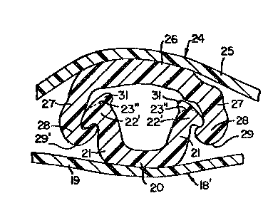
In Fig. 6, the male profile portion 18' in
acco~dance with this invention is disclo6ed in
detail wherein hook projection~ 31 on hook portions
22' can be seen extending ~rom the broken linefi 23"
shown therein to form a reduced gap between hook
poL~ions 22' to thereby phyfiically hinde~ the
D-13767
.
.
,
:
~traddlin~ of a male closure element and a female
closure element a6 previously shown in Fig. 2.
Accordangly, the de~ired hindrance of the ~raddle
po6ition that could occur between a male closure
element ~nd a female clo6ure element i8 obtained,
and likewi&e, the other de~ired charac~eri~tic of
ease of occlu~ion i~ enabled by providing a guiding
action for the hoo~ ~urfa~e6 of ~he female clo6ure
element to 61ide along the out~ide 6urfacez 32 of
hook portion~ 22l of the male ~lo~ure element. Such
guidance help~ direct the male and female closure
elements into their proper occluded position~ A8
will be appreciated by tho~e 6killed in the art,
hook projection6 31 may be any suitable length ~o as
to virtually clo6e the gap or void between them and
preclude entcance thecein of the hook and web
po~tion6 of ~he female clo~ure element, thereby
virtually in6uring occlu~ion and eliminating the
pos~ibili~y of st~addling between the male and
female closure elements.
Manufacturing consideration6 may limit the
extent to which the hoo~ projection# 31 are brought
clo6e together the~eby ~educing the guidance effect
between the male clo6ure element of thi~ invention
and a conventional interlocking female closure
element. Sati~factory re~ult6 have been obtained
when the hook projections 31 have length6, on a
proportionate scale to the occluded heigh~ and
occluded width of the interlocking clo6ure fa6tening
device, of between about 5 mil6 and about B mil~ as
measured between the dotted lines 33 6hown in Fig.
S. However, it i~ preferred that hook pro3ection6 31
~-13767
`
:` :
_ 9 _
have lengths, on a propo~tionate 6cale to the
occluded height and occluded width of the
in~e~locking clo~ure fastening device, o-E be~wesn
about 5 mil~ and about 20 mil~, as ~uch lengths
provide ~he aforementione~ desired characteristic~
to interlocking clo~ure fastening devices.
In accordance with a preferred embodiment
of this invention~ certain part~ of the hook
portion~ 22' of the male clo6ure element o~ this
invention have length~, on a proportionate ~cale ~o
the occluded height and occluded width of the
interlocking clo6ure fa~tening device, of between
about 5 mils and about 10 milfi as measured between
the dotted line~ 34 6hown in Fig. 6.
As employ0d herein, the term
llpLopOrtiOnate" i6 to indicate the relative
proportions of the clo~ure elements of the
interlocking clo6ure fastening device when the male
and female closure element6 ale occluded. Thus,
when the interlocking closure fastening device of
this invention has an occluded height of between
about 60 mil~ and about 85 mils, and an occluded
width of bet~een about 95 mils and about 12S mils,
the length~ of the hook po~tion~ of the male clo~ure
element are between about 5 mils and about 10 mil8,
and the lengths of the hook p~ojections of the male
clo~ure element are between about 5 mil6 and about
20 mil6 on a proportionate 6cale to the occluded
height and occluded width of the interlocking
clo~ure fa6tening device. Accordingly, when the
occluded height and occluded width o~ the
interlocking clo~ure fa~tening device of this
D-13767
-- 10 --
invention a~e either in~rea6ed or decrea~ed, then
the length6 of the hook portion~ and hook
projection~ of ~he male clo6ure element ~hould be
proportionately increa6ed or decrea~ed ~o maintain
the relative proportions of the cl06ure elements.
Fig 7 ~how6 a male closure element in
accordance with this invention in a mi~aligned
position with respect to a female closure elemen~
just prior to occlu~ion therewith. I~ can be seen
from Fig. 7 that even though the male clo~ure
element and the female clos~lre ele~ent are
misaliqned, a~ much a~ 6hown in Fig. 3, they will be
guided into the de~ired occluding alignment by hook
peojections 31 extending toward each other from male
hook portionx 22' for ultimate interlocking
occlusion.
In Fig. 8 it can be seen that when the male
clo~ure element in accordance with thi6 invention i8
properly aligned with a female closure element just
prior to occlusion, ~uch will not only lead to
greater ease of occlu~ion therebetween, but will
also inhibit the movement of the male closure
element and the female clo6ure element into a
non-occluded ~traddle ~o~ition.
Contac~ing pre66ure applied to interlocking
clo6ure fa~tening devices aligned in the po~ition
~hown in Fig. 8 will interlock the inventive male
profile portion 18' and the female profile portion
24 in the normally occluded po6ition ~hown in Fig. 9.
It should be noted that during the
occlusion operation o~ ~emale profile portion 24 and
male profile portion 18', at least one of the base
D-13767
.
. .
.
portions 26 and 20 flexes, or the web~ 27 and 21
flex, 01 ~he hooks 28 and ~2~ flex, or a combination
of these parts flex to achieve occlusion.
Generally, the clo~ure fa~tening device of
this inven~ion may be formed from thermoplastic
material~ such a6 polyethylene, polypropylene,
nylon, or the like, or from a combination thereof.
Thus, resins or mixtures of resins such ~s hi~h
density polyethylene, medium density polyethylene
and low density polyethylene may be employed to
prepare the novel closure device of this invention.
The closure fastening device of the
invention may be manufactured by extrusion, or other
known me~hods of producing such device~. The
closure fastening device can be manufactured as
individual clo6ure elements for later attachment ~o
a film, or the clo6ure ~roPile portions can be
manufactuLed integral with a film. In addition, the
closure fastening device can be manufactured with or
without flange poLtions on one o~ both of the
clo~ure elements depending upon intended use or
expected additional manufacturing operations.
In the practice of the in~tant invention,
the closure fastening device may be integrally
formed with the sidewalls of a container, or
connec~ed to a container, o~ to a film to be formed
into a container, by the u~e of any of many known
method6. A thermoelectric device can be applied to
a film in contact with a flange portion of a closure
element or the thermoelectric device can be applied
to a ~ilm in contact with the basQ portion of a
closure element having no flange portion, to cause a
D-1~767
;': .~ :, '
:'
- 12 -
tran~fer of heat through the film to pLoduce melting
at the interface of the ~ilm and the flange por~ion
or base poction of the closure element. On cooling,
the inte~face region join~ the ~ilm and ~he clo6ure
element. The thermoelectIic device can be heated
rotary disc6, or re~is~ance heated slide wirea~ or
traveling heater bands, or the like. The connection
between the film and the closure element can also be
established by the u~e of hot melt adhe~ives, or hot
3et~ of air to the interface, or ultra~onic heating,
or other known method~. Generally, the closure
fa~tening device and films can be made from a heat
sealable material ~o that a containe~ can be formed
economically by heat sealing the aforementioned
component~ to form the container.
The clo~ure fa6tening de~ice of this
invention provide~ many advantage~ for use in
containers to be u~ed by con~umers. For example,
the closure device i8 ea6y to occlude and doe6 not
tend to twi~t and dis~ort during attempted occlu~ion
a~ in the ca~e of some prior art device~ such as the
arrowhead-6haped device employed with a container
available under the tradename ZIPLOC from Dow
Chemical Co~pany of Midland, Michigan. This
provides convenience in the occluding operation.
In addition, the C1Q6Ure fastening device
i8 more difficult to deocclude from the inside of
the containers than from the outside of the
containers thereby providing more secure sontainment
of goods such as food products. The profile
portion6 of the closure device have approximately
uniform cro6s-6ection~. Thi~ not only simplifies
D-13767
- 13 -
the manufacturing of the device but it also
contributes to the phy~ical ~lexiblity of the
device, which i~ a desirable property.
A clo~ure fa~tening device in accordance
~ith ~hi~ invention can al~o be used as a flexible
~traw because a good seal at the engaged 6urfaces i8
possible and a compartment defined by the occludsd
clo~ure elements provides a pas6ageway which does
not collapse when the closure ~a~tening 2evice i8
bent moderately.
Generally, the closure fastening device of
thi~ invention can be manufactured in a variety of
forms to suit the intended use. In addition, the
male and female closure elements can be position2d
on oppo~ite 6ides of a film. Such an embodiment
would be 6uited for enwLapping an object or a
collection of object~ ~uch as wire~. Generally, the
male and female clo~ure element~ on a film ~hould be
pa~allel to each other, but ~his would depend on the
intended use.
We wi~h it to be understood that we do not
de~ire to be limited to the exact detail~ of
construction ~hown and described, foL alternative
embodiment~ will occur to a per60n skilled in the
art.
Having thus de6cribed the invention, what
we elaim a6 new and desi~e to be secured by Letter~
Patent i8 as follow~:
D-13767