Language selection

Search

Patent 1269863 Summary

Third-party information liability

Some of the information on this Web page has been provided by external sources. The Government of Canada is not responsible for the accuracy, reliability or currency of the information supplied by external sources. Users wishing to rely upon this information should consult directly with the source of the information. Content provided by external sources is not subject to official languages, privacy and accessibility requirements.

Claims and Abstract availability

Any discrepancies in the text and image of the Claims and Abstract are due to differing posting times. Text of the Claims and Abstract are posted:

  • At the time the application is open to public inspection;
  • At the time of issue of the patent (grant).
(12) Patent: (11) CA 1269863
(21) Application Number: 1269863
(54) English Title: MASS-MEASURING AND FORCE-MEASURING DEVICE
(54) French Title: DISPOSITIF MESUREUR DE MASSE ET DE FORCE
Status: Term Expired - Post Grant
Bibliographic Data
(51) International Patent Classification (IPC):
  • G01G 3/08 (2006.01)
  • G01G 3/12 (2006.01)
  • G01G 21/16 (2006.01)
  • G01G 21/23 (2006.01)
  • G01G 21/24 (2006.01)
(72) Inventors :
  • SANER, KASPAR (Switzerland)
(73) Owners :
  • K-TRON TECHNOLOGIES, INC.
(71) Applicants :
  • K-TRON TECHNOLOGIES, INC. (United States of America)
(74) Agent: NORTON ROSE FULBRIGHT CANADA LLP/S.E.N.C.R.L., S.R.L.
(74) Associate agent:
(45) Issued: 1990-06-05
(22) Filed Date: 1986-03-25
Availability of licence: N/A
Dedicated to the Public: N/A
(25) Language of filing: English

Patent Cooperation Treaty (PCT): No

(30) Application Priority Data:
Application No. Country/Territory Date
85 810 127.2 (European Patent Office (EPO)) 1985-03-25

Abstracts

English Abstract


Abstract of the Disclosure
A mass-measuring and force-measuring device which com-
prises a frame, a load-bearing component guided at
right angles and parallel, a pathless measuring system
and means for transmitting the load to the measuring
system, which possess a. lever which is connected to the
frame via a first plate having at least one joint and
non-rotatably and non-displaceably mounted on the said
lever, and is connected to the load-bearing component
via a second non-rotatably and non-displaceably mounted
plate having at least two joints.


Claims

Note: Claims are shown in the official language in which they were submitted.

The embodiments of the invention in which an exclusive
property or privilege is claimed are defined as follows:-
1. A mass-measuring and force-measuring device
which comprises a frame, a load-bearing component
guided at right angles and parallel, a pathless
measuring system and means for transmitting the load
to the measuring system, wherein these means possess
a lever which is connected to the frame via a first
plate having at least one joint and non-rotatably and
non-displaceably mounted on the said lever, and is
connected to the load-bearing component via a second
plate which has at least two joints and is non-
rotatably and non-displaceably mounted.
2. A mass-mesuring and force-measuring device
as claimed in claim 1, wherein each plate has a hole
for holding the lever and at least one hole for
fastening the said plate.
3. A mass-measuring and force-measuring device
as claimed in claim 2, wherein the first plate has a
single horizontally arranged band joint.
4. A mass-measuring and force-measuring device
as claimed in claim 3, wherein the second plate has
two parallel, horizontally arranged band joints.
5. A mass-measuring and force-measuring device
as claimed in claim 2, wherein both plates have a
slot which extends around the stated hole through at
least 180°, and the said plates are provided with a
pair of band joints whose common horizontal axis runs
through the center of the stated hole and lies in the
horizontal plane through the axis of the lever.

6. A mass-measuring and force-measuring device
as claimed in claim 5, wherein the second plate has a
second tongue shaped joint.
7. A mass-measuring and force-measuring device
as claimed in claim 6, wherein the second joint is
located outside the horizontal plane through the axis
of the lever and acts as a primary joint.
8. A mass-measuring and force-measuring device
as claimed in claim 6, wherein the second joint lies
outside the horizontal plane through the axis of the
lever and acts as a secondary joint.
9. A mass-measuring and force-measuring device
comprising a frame, a load-bearing component guided
at right angles and parallel, a pathless measuring
system and means for transmitting a load to the
measuring system wherein the means for transmitting
includes a lever being connected to the frame by a
first plate having at least one joint and being con-
nected to the load-bearing component by a second
plate having at least two joints wherein each of said
first and second plates includes a first hole pene-
trated by the lever, whereby the lever and each first
hole form a press-fit connection, and whereby each of
said first and second plates are connected, non-
rotatably and non-displaceably to the lever.
10. A mass-measuring and force-measuring device
as claimed in claim 9, wherein each plate includes at
least one second hole for fastening said plate.

11. A mass-measuring and force-measuring device
as claimed in claim 10, wherein the first plate
includes a single horizontally arranged band joint.
12. A mass-measuring and force-measuring device
as claimed in claim 11, wherein the second plate
includes two parallel, horizontally arranged band
joints.
13. A mass-measuring and force-measuring device
comprising: a frame, a load-bearing component guided
at right angles and parallel, a pathless measuring
system and means for transmitting a load to the
measuring system, wherein the transmitting means
include a lever which is connected to the frame by a
first plate having at least one joint non-rotatably
and non-displaceably mounted on said lever, and being
connected to the load-bearing component by a second
plate having at least two joints, and being non-
rotatably and non-displaceably mounted on said lever;
wherein each plate includes a first hole for holding
the lever and at least one second hole for fastening
said plate; and wherein both plates include a slot
extending around the first hole through at least
180°, and said plates are provided with a pair of
band joints having a common horizontal axis running
through the center of the first hole and lying in the
horizontal plane through the axis of the lever.
14. A mass-measuring and force-measuring device
as claimed in claim 13, wherein the second plate has
a second tongue-shaped joint.

15. A mass-measuring and force-measuring device
as claimed in claim 14, wherein the second joint is
located outside the horizontal plane through the axis
of the lever and acts as a primary joint.
16. A mass-measuring and force-measuring device
as claimed in claim 14, wherein the second joint lies
outside the horizontal plane through the axis of the
lever and acts as a secondary joint.
17. A mass-measuring and force-measuring device
as claimed in claim 9, wherein each of said joints
comprises a band limited at least on one side of the
plate by a horizontal groove and having, measured in
the longitudinal direction of the lever, an extension
smaller than the portions of the plate adjacent to
the band, and an extension smaller than the hole
penetrated by the lever.
18. A mass-measuring and force-measuring device
as claimed in claim 17, wherein each of said bands is
limited by a pair of horizontal grooves arranged
opposite to each other in the plate.
19. A mass-measuring and force-measuring device
as claimed in claim 9, wherein each of said holes
penetrated by the lever has circular cross-section.
20. A mass-measuring and force-measuring device
as claimed in claim 9, wherein the lever is connected
with said frame only by the first plate and wherein
the lever is connected with said load bearing
component only by the second plate.

Description

Note: Descriptions are shown in the official language in which they were submitted.


~2~9863
-- 1 --
K-TRON Patent AG ZUrich
Mass-measurin~ and for~e-measuring device
The present invention relates to a mass-measuring
and force-measuring device comprising a frame, a load-
bearing component running at right angles and parallel,a pathless measuring system and means for transmitting
the load to the measuring system. Such devices, which are
also referred to as tied balances, are disclosed in, for
example, U.S. Patent 3,423,999. If, in such devices, the
measuring system is removed, they form a kinematic system
with a single degree of freedom. A pathless measuring
system is one in which the movement permitted by the
measuring system is virtual. Such measuring systems con-
sist, for example, of at least one vibrating string or one
wire strain gage and electronic3 suitable for the purpose.
The means for transmitting the load to the measur-
ing system generally possess atleast one lever which, in
transmitting the force, reduces it. Such a lever is dis-
closed in, for example, U.S. Patent 4,088,198. The class-
ical knife edges and blade-bearing recesses of the known
lever apparatuses, which permit large rotational movements,
are generally replaced in tied balances by resilient
joints, such as universal joints and band joints. For a
given input load, such elements must permit a very short~
input arm of the reducing lever without diminlshirlg the
quality, i.e. the preclsion of transmission or the
reduction ratio.
The object of the invention is to provide elements
which permit medium-si~ed or even small, commercially
acceptable production series.
This object i~ achieved, according to the in-
vention, if these means possess a lever which is
cbnnected to the fra'me.via a~first plate which has at
'~

least one joint and is mounted non-rotatably and non-
displaceably on the said lever', and is connected to
the load-bearing component via a second plate which has
at least two joints and is mounted non-rotatably and
non-displaceably.
The attached drawing schematically illustrates
examples of the subject of the invention.
Fig. 1 shows a first embodiment,
Fig. 2 and 3 each show a plate,
~o Fig. 4 and 5 each show a version of Fig. 2 and 3,
Fig. 6 shows a second embodiment, and
Fig. 7 shows the plate of the embodiment according to
Fig. 6.
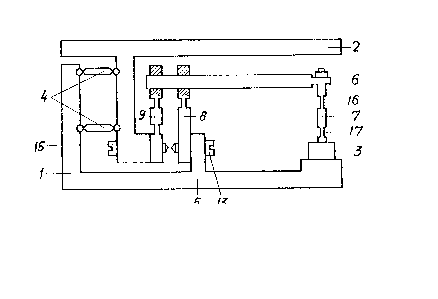
Fig. 1 - 3 show:a first example. The device
has a frame 1, a load-bearing component 2t and a
measuring system 3 fastened on the frame 1. The load-
bearing co~ponent:is guided parallel and at ri8ht angles
by means of connecting rods 4. A lever 6 is pivotably
mounted on a support 5 of the frame 1. At its left-
hand end, the lever 6 i9 ¢onnected to the load-benring
component 2. It acts on the input of measurlng system 3
via a stilt 7 fastened to its right-hand end.
The lever 6 i8 provided with two plates 8 and 9.
The p].ate 8 (Fig. 2) consists of a flat, essentially
rectangular plate which has an upper hole 10, two lower
holes 11, preferably provided with a thread, and two
horizontal g~ooves whi~h form a vertical band joint 12.
The plate 8 is mounted non-rotatably and non-displace-
ably, i.e. by means o a sQ-called press fit, via the
hole 10, on the lever ~. The said plate is fastened to
the support 5 of the frame 1 by means of screws 130 The
plate 9 (Fig. 3) has the same form as the plate 8 but
possesses a second band joint 14. The distance from the
band joints 12 to the center of the hole 10 is the same
for both plates 8 and 9. The plate 9 sits non-rotatably

i3
-- 3
and non-displaceably on the lever 6. The said plate is
fastened to the load-bearing c'omponent 2 by means of
screws 15.
The stilt 7 has two narrower sections 16 and 17,
each of which forms a Joint. The said stilt is fastened
at its upper end to the lever 6, and at its lower end
to the input of the measuring sys.tem 3. It thus acts
as a tie bar. The narrower section 16 is arranged so
that its distance from..the longitudinal axis of the
.. 10 lever 6 is the same as ~he distance of the band joint
12 from the center of the hole 10.
The device described functions as follows. If
a mass is placed on the load-bearing component 2, its
weight is transmitted via the plate 9 to the lever 6,
the said plate acting as a traction element. The band
joint 12 acts as a primary joint, and the band joint
14 acts as a secondary joint. The lever 6 is pivoted
about the band joint 12 of the plate 8. It is clearly
understood that this is a virtual rotation. The stilt
7 trans~its the so-called sensed force to the measuri.ng
system 3. The narrower section 16 acts as a primary
joint, and the narrower section 1.7 as a secondary joi~t.
Fig. 4 and 5 illustrAte a version of the
embodiment oE the plates according to Fig. 2 and 3~ A
sernicircular ~lot 18 is provided at the upper end of the~
plates 8 and 9. Two ho.rizontal grooves which form two
band ~oints 19 and 20 are provided on each of the two
sides of the slot 18. This pair of band joints 19 and
20 corresponds to the band joint 12 of Fig. 2 and 3,
but is located in the horizontal plane through the
longitudinal axis of the lever 6. The second band joint
14 of plate 9 in Fi8. 3, which joint acts as a secondary
joint is replaced, in the embodiment of Fig. 5, by a
tongue shaped band joint 21 which has greater flex-ibility
in respect of bending and torsional moments.

363
The lower part of the two plates 8 and 9 shown
in Fig. 4 and 5 is reduced to half the thickness from
the shoulder 22 onward. The plane 23 of these lower
parts runs through the middle of the band joints 19 and
20, or 19, 20 and 21. The pla~es 8 and 9 can of course
be interchanged.
Fig. 6 shows an example in which the load-bear-
ing component 2 is guided at ri8ht angles and parallel
by means of parallel connecting rods 24. The measuring
10 system 3 is fastened to an arm 25 of the load-bearing
component 2. The lever ~ is provided with two plates
26. It is connected to the frame 1 by means of the
first plate 26. It is connected to the load-bearing
component 2 via the second plate 26. In this example,both
plates 26 are identical. The right-hand end of the lever 6
(as viewed in Fig. 6) iB connected to the measuring
system 3 via a stilt 7 which is illustrated schematically
and acts as a pressure rod.
Fig. 7 shows the plate 26. In the case of the
plate 26, the slot 18 of the embodiment according to
Fig. 4 and 5 is no longer semicircular but virtually
completely circular, so that the resulting tongue 27,
which acts as a primary Joint, has a width which
essentially corresponds to the thlckness of the plate
25 26. The slot 18 and the hole 10 are concentric. The
remaining elements are as described in connec~ion with
Fig. 4. The tongue 27 could, if necessary, also be in
the form of the joint 21 (Fig. 5), i.e. thinner than
the plate 26 itself.
In this embodiment of the plates 26, the
primary joints $ormed by the tongue 27 thus lie outside
the horizontal plane through the axis of the lever 6,
while the pair of secondary joints 19 and 20 lie in
this plane. Both plates 26 may be regarded as resilient
traction elements having the same transverse flexibility.

" ~2~363
The skilled worker can readily calculate that elongation
of the p~rallel connecting rods 24 essentially has no
ef~ect on the transmission ratio. This embodiment is
advantageous where it is n.ecessary for the entire device
to have a small. height.
In the exampleq described, the band joints 12
14, 19 and 20 lie in the middle plane of the plates.
However, they can also be located in a position dis-
placed from this plane., permitting a further reduction
in ~he length of the effective input arm of the lever 6.

Representative Drawing
A single figure which represents the drawing illustrating the invention.
Administrative Status

2024-08-01:As part of the Next Generation Patents (NGP) transition, the Canadian Patents Database (CPD) now contains a more detailed Event History, which replicates the Event Log of our new back-office solution.

Please note that "Inactive:" events refers to events no longer in use in our new back-office solution.

For a clearer understanding of the status of the application/patent presented on this page, the site Disclaimer , as well as the definitions for Patent , Event History , Maintenance Fee  and Payment History  should be consulted.

Event History

Description Date
Inactive: Expired (old Act Patent) latest possible expiry date 2007-06-05
Inactive: IPC from MCD 2006-03-11
Inactive: Entity size changed 2002-05-17
Grant by Issuance 1990-06-05

Abandonment History

There is no abandonment history.

Fee History

Fee Type Anniversary Year Due Date Paid Date
Registration of a document 1997-07-17
Reversal of deemed expiry 2001-06-05 1998-06-01
MF (category 1, 8th anniv.) - small 1998-06-05 1998-06-01
Reversal of deemed expiry 2001-06-05 1999-06-01
MF (category 1, 9th anniv.) - small 1999-06-07 1999-06-01
Reversal of deemed expiry 2001-06-05 2000-04-17
MF (category 1, 10th anniv.) - small 2000-06-05 2000-04-17
Reversal of deemed expiry 2001-06-05 2001-04-30
MF (category 1, 11th anniv.) - small 2001-06-05 2001-04-30
MF (category 1, 12th anniv.) - standard 2002-06-05 2002-05-02
MF (category 1, 13th anniv.) - standard 2003-06-05 2003-05-12
MF (category 1, 14th anniv.) - standard 2004-06-07 2004-04-28
MF (category 1, 15th anniv.) - standard 2005-06-06 2005-04-14
MF (category 1, 16th anniv.) - standard 2006-06-05 2006-04-21
Owners on Record

Note: Records showing the ownership history in alphabetical order.

Current Owners on Record
K-TRON TECHNOLOGIES, INC.
Past Owners on Record
KASPAR SANER
Past Owners that do not appear in the "Owners on Record" listing will appear in other documentation within the application.
Documents

To view selected files, please enter reCAPTCHA code :


To view images, click a link in the Document Description column. To download the documents, select one or more checkboxes in the first column and then click the "Download Selected in PDF format (Zip Archive)" or the "Download Selected as Single PDF" button.

List of published and non-published patent-specific documents on the CPD .

If you have any difficulty accessing content, you can call the Client Service Centre at 1-866-997-1936 or send them an e-mail at CIPO Client Service Centre.


Document
Description 
Date
(yyyy-mm-dd) 
Number of pages   Size of Image (KB) 
Cover Page 1993-09-22 1 15
Abstract 1993-09-22 1 13
Claims 1993-09-22 4 128
Drawings 1993-09-22 1 42
Descriptions 1993-09-22 5 153
Representative drawing 2002-03-04 1 8
Courtesy - Certificate of registration (related document(s)) 1998-11-24 1 114
Fees 1996-05-22 1 57
Fees 1997-05-13 1 64
Fees 1994-05-20 1 55
Fees 1995-04-26 1 57
Fees 1993-04-13 1 49
Fees 1991-10-31 1 60