Language selection

Search

Patent 1270026 Summary

Third-party information liability

Some of the information on this Web page has been provided by external sources. The Government of Canada is not responsible for the accuracy, reliability or currency of the information supplied by external sources. Users wishing to rely upon this information should consult directly with the source of the information. Content provided by external sources is not subject to official languages, privacy and accessibility requirements.

Claims and Abstract availability

Any discrepancies in the text and image of the Claims and Abstract are due to differing posting times. Text of the Claims and Abstract are posted:

  • At the time the application is open to public inspection;
  • At the time of issue of the patent (grant).
(12) Patent: (11) CA 1270026
(21) Application Number: 1270026
(54) English Title: SEALING METHOD FOR BEARING ASSEMBLIES
(54) French Title: METHODE DE SCELLEMENT DE PALIERS
Status: Expired and beyond the Period of Reversal
Bibliographic Data
(51) International Patent Classification (IPC):
  • F16C 33/76 (2006.01)
  • F16C 33/80 (2006.01)
  • F16J 15/40 (2006.01)
  • F16J 15/447 (2006.01)
(72) Inventors :
  • GRZINA, ANTHONY (Australia)
(73) Owners :
  • WARMAN INTERNATIONAL LIMITED
(71) Applicants :
  • WARMAN INTERNATIONAL LIMITED (Australia)
(74) Agent: SMART & BIGGAR LP
(74) Associate agent:
(45) Issued: 1990-06-05
(22) Filed Date: 1986-10-21
Availability of licence: N/A
Dedicated to the Public: N/A
(25) Language of filing: English

Patent Cooperation Treaty (PCT): No

(30) Application Priority Data:
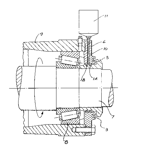
Application No. Country/Territory Date
PH 3024 (Australia) 1985-10-22

Abstracts

English Abstract


ABSTRACT
A bearing assembly has at least two seal rings spaced a
short distance apart from each other to form the inner sealing
elements. A labyrinth passage forms the outer sealing element.
A passageway extending externally of the bearing assembly into the
space between at least two of the spaced apart seal rings has an
automatic grease feeder connected to it to discharge grease into
that space.


Claims

Note: Claims are shown in the official language in which they were submitted.


20392-301
THE EMBODIMENTS OF THE INVENTION IN WHICH AN EXCLUSIVE
PROPERTY OR PRIVILEGE IS CLAIMED ARE DEFINED AS FOLLOWS:
1. In a bearing assembly for a rotating shaft assembly a
bearing seal comprising:
at least two piston rings, spaced apart from each other
and supported on the bearing assembly, to form an inner sealing
element;
a labyrinth passage forming an outer sealing element;
a groove located on said rotating shaft assembly to
receive said piston rings;
a passageway extending externally of the bearing
assembly into a space between at least two of the said spaced
apart piston rings; and
an automatic grease feeder connected to said passageway
to discharge grease into the said space,
whereby grease discharged from said automatic feeder
flows under pressure to force said piston rings apart and then to
flow over said piston rings to cause a layer of grease to lie
between said piston rings and the rotating shaft assembly, and to
flow through said labyrinth and through said inner sealing element
to form a seal against the ingress of material past the bearing
seal.
2. A bearing seal according to Claim 1 wherein the space

20392-301
located intermediate said at least two piston rings is configured
and dimensioned to receive an annular projection on the rotating
shaft assembly.

Description

Note: Descriptions are shown in the official language in which they were submitted.


12~00~6
The present invention relates to an improved seal for
bearing assemblies.
Bearing assemblies are used in rotodynamic fluid machines
such as pumps, turbines, agitators and the like to house
bearings and support a shaft which normally protrudes from both
ends of the bearing housing to connect the rotating element(s)
of the fluid machine to the fluid machine drive.
Bearings require a clean well lubricated environment to
operate. With the shaft protruding from the bearing assembly
from either one or two ends it is necessary to enclose and seal
the bearing housing ends. As the shaft rotates in a stationary
housing it is necessary to use seals which minimise the
frictional losses and heat generation.
Fluid machines often operate in harsh environments where
air or water borne contaminants are present at or near the
bearing housing and enclosures. Centrifugal slurry pumps in
particular are open to severe environmental influences as the
shaft er.ters the pump by way of a gland arrangement which in
its standard form is designed to leak slightly to allow
lubrication of the gland sealing elements. This small leakage
is in close proximity to the end of the bearing housing.
The bearing seals which fit into the ends of the bearing
housing can be selected from any number of known types or
special types could be developed. Certain seal arrangements
incorporate a labyrinth (small clearance passageway) to affect
the sealing and others incorporate element(s) which rub on the
rotating shaft or a shaft mounted component. As such all seals
have a potential to allow contaminants into the bearing housing

127~0Z6
20392-301
which can become worse as the sealing element(s) wear.
A typical prior art bearing assembly is illustrated in
Figure 1 in whlch the pump impeller shaft 7 is held by bearings 8
in the bearing housing 9. This pump uses end closures
incorporating two piston rings 1 located in grooves 2 on the shaft
collar as the inner sealing elements and a labyrinth passage 3 as
the outer sealing elements. This form of sealing has proved more
effective when the labyrinth passage 3 is purged with grease.
Grea8e i8 pumped by means of a grease gun (not shown) being
connected to the grease nipple 4 through the flushing bore 5, in
the bearlng housing end cover 6, to the outside of the outer
piston ring 1 into the labyrinth passage 3.
The grease purge is normally applied at regular
intervals but in some applications has not proved entirely
effectlve in keeping contaminants away from the piston ring ceals
which have only limited abillty to seal against the usual water
borne contaminants experienced in the mining industry.
The main problem with the existing grease purging
arrangement is that grease is flung out of the labyrinth passage
by centrifugal action when the pump is running. The greasing
perlod, in general practice, is longer than the time taken for the
grease to be expelled by centrifugal action. Potential
contaminants can more easily enter the labyrinth if no grease is
present, especially if the pump is stopped, and work their way
past the piston rings to eventually reach the bearings.
The pre~ent invention seeks to overcome these
disadvantages by providing in a bearing assembly for a rotating
, ... .
'~

1`Z7~26
20392-301
shaft assembly a bearing seal comprising, at least two piston
rings, spaced apart from each other and supported on the bearing
assembly, to form an inner sealing element; a labyrinth passage
forming an outer sealinq element; a groove located on said
rotating shaft assembly to receive said piston rings; a passageway
extending externally of the bearing assembly into a space between
at least two of the said spaced apart piston rings; and an
automatic grease feeder connected to said passageway to discharge
grease into the said space, whereby grease discharged from said
automatic feeder flows under pressure to force said piston rings
apart and then to flow over said piston rings to cause a layer of
grease to lie between said piston rings and the rotating shaft
as embly, and to flow through said labyrinth and through said
inner sealing element to form a seal againæt the ingress of
materlal past the bearing seal.
The invention will now be described with reference to
Flgure 2 which illustrates one embodlment of the present
invention. The designation numerals appearing in this drawing
represent the same features as the features designated by the same
numeral~ in Flgure 1.
The sealing arrangement is physically very similar to
the seal arrangement shown in Figure 1 in that it consists of two
seal rings lA and lB spaced a short distance apart to form the
inner seal elements and a labyrinth 3 forming the outer seal
element. The lmprovement is embodied in the way the grease is
used not so much to flush contaminants out but to provlde a
pressurlsed grease barrler, between the two seal rlngs, which is
. .

1;:700Zti
20392-301
maintained at all times regardless of whether the pump is stopped
or running.
The grease is applied via feed passageway 10 from an
automatic grease feeder 11, located on the bearing housing end
cover 6, to the space between the two piston rings 1. Thus a
small but constant amount of grease under pressure is supplied
regardless of pump operation.
The grease can travel in two directions. The grease
which passes the inner seal ring lB and enters the bearing housing
assists in lubrication of the bearings 8. The grease which passes
the outer seal ring lA enters the labyrinth seal 3 and
.S
'~ ,
.
. -. .

12700Z6
~ ile the pump is running the grease will be expelled through
the labyrinth passage to the outside by centrifugal action,
thereby flushing out any contaminants at the same time.
An additional advantage of the improved seal is that any
wear of the sealing elements will not adversely affect the
overall sealing ability of the arrangement as the grease
barrier is maintained at all times.
Thus the improved sealing arrangement will reduce bearing
failures caused by outside contaminants. While the pump is
running the potential contaminants will have their initial
energy killed by the high energy spinning labyrinth before
coming up against the pressurised grease barrier. While the
pump is stopped, any contaminants will not be able to pass the
pressurised grease barrier.
It should be obvious to people skilled in the art that
modifications could be made to the seal arrangement without
departing from the spirit or scope of the present invention.

Representative Drawing
A single figure which represents the drawing illustrating the invention.
Administrative Status

2024-08-01:As part of the Next Generation Patents (NGP) transition, the Canadian Patents Database (CPD) now contains a more detailed Event History, which replicates the Event Log of our new back-office solution.

Please note that "Inactive:" events refers to events no longer in use in our new back-office solution.

For a clearer understanding of the status of the application/patent presented on this page, the site Disclaimer , as well as the definitions for Patent , Event History , Maintenance Fee  and Payment History  should be consulted.

Event History

Description Date
Time Limit for Reversal Expired 2006-06-05
Inactive: IPC from MCD 2006-03-11
Letter Sent 2005-06-06
Grant by Issuance 1990-06-05

Abandonment History

There is no abandonment history.

Fee History

Fee Type Anniversary Year Due Date Paid Date
MF (category 1, 8th anniv.) - standard 1998-06-05 1998-05-22
MF (category 1, 9th anniv.) - standard 1999-06-07 1999-05-18
MF (category 1, 10th anniv.) - standard 2000-06-05 2000-05-30
MF (category 1, 11th anniv.) - standard 2001-06-05 2001-05-23
MF (category 1, 12th anniv.) - standard 2002-06-05 2002-05-22
MF (category 1, 13th anniv.) - standard 2003-06-05 2003-05-23
MF (category 1, 14th anniv.) - standard 2004-06-07 2004-05-20
Owners on Record

Note: Records showing the ownership history in alphabetical order.

Current Owners on Record
WARMAN INTERNATIONAL LIMITED
Past Owners on Record
ANTHONY GRZINA
Past Owners that do not appear in the "Owners on Record" listing will appear in other documentation within the application.
Documents

To view selected files, please enter reCAPTCHA code :


To view images, click a link in the Document Description column (Temporarily unavailable). To download the documents, select one or more checkboxes in the first column and then click the "Download Selected in PDF format (Zip Archive)" or the "Download Selected as Single PDF" button.

List of published and non-published patent-specific documents on the CPD .

If you have any difficulty accessing content, you can call the Client Service Centre at 1-866-997-1936 or send them an e-mail at CIPO Client Service Centre.

({010=All Documents, 020=As Filed, 030=As Open to Public Inspection, 040=At Issuance, 050=Examination, 060=Incoming Correspondence, 070=Miscellaneous, 080=Outgoing Correspondence, 090=Payment})


Document
Description 
Date
(yyyy-mm-dd) 
Number of pages   Size of Image (KB) 
Abstract 1993-09-20 1 10
Claims 1993-09-20 2 32
Drawings 1993-09-20 2 36
Descriptions 1993-09-20 5 137
Representative drawing 2001-07-04 1 17
Maintenance Fee Notice 2005-07-31 1 172
Fees 1997-05-19 1 65
Fees 1996-05-23 1 65
Fees 1994-05-24 2 99
Fees 1995-05-24 1 65
Fees 1993-05-18 1 32
Fees 1992-01-15 1 42