Note: Descriptions are shown in the official language in which they were submitted.
J~
WINDOW B~R SECURITY_ SYSTEM
FIELD OF THE, INVENTION
This invention relates to a window b~r guard
system for discouraging breaking and entry through
5 window openings.
BACKGROUND OF THE INV NTION
Window bar guard systems have been u~ed for some
time in an effort to thwart or discourage breaking and
entry into a house or other establishment through a
window opening~ A telescoping window bar guarcl system
is disclosed in United States patent 3,738,062. The
system includes two horizontal membexs having an
extensible portion. One side of the grillwork is
pi.votally connected to the window frame. The extensible
portion is extended and secured to the other side of the
window frame by a lock arrangement. In the event of
fire or the need to c:Lean the window, the system may be
unlocked and swung outwardly. The extensible portion is
not secured to the horizontal members so that the
extensible portion can be retracted in order to release
the bar system. Due to the free telescopic nature oF
the bars of the window system, prying with a crowbar can
weaken the connection of either side of the bar guard
system to the window frame to allow illegal entry
through the window.
A telescopic bar window system, which entails
locking ~he relative positions of the telescoping bars,
is disclosed in United States patent 4,437,265. Lock
portions are used on at least two of the telescoping
horizontal bar members to prevent relative movement
therebetween. The ends of the bars are fastened to the
opposite sides of the window frame. However, to remove
the bar system from the window it is necessary to unlock
the telescoped bars. The lock provided, in accordance
with this`patent, is a friction type lock which can be
readily tampered with to release and thereby allow
ille~al entry to a building through the window.
Fixed bar arrangements for window bar guard
systems are disclosed in United States patents
.
.
~7~3~S~
2,999,682, 2,222,667, 4,019,281 and 4,358,912. Due to the fixed
nature of the bars, various mounting systems are employed to
permit outward withdrawal of the har gratings by complete removal
or pivotal action. Pivotal action for the bar systems is ~urther
demonstrated in United States patent 3,953,939, where a lower
segment of the bar system is pivoled upwardly when releasedO
SUMMARY OF INVENTION
According ko an aspect of this invention a window bar guard
system for discouraging breaking and entry through a window, said
system comprises a rigid bar grillwork having a plurality of
spaced-apart parallel first bar assemblies and a plurality of
spaced-apart parallel second bar assemblies interconnecting the
first bar assemblies and extending essentially perpendiculaxly
thereto. The bar grillwork spans a window opening to block
human entry through the grillwork. ~eans secures opposite ends
of first bar assemblies to corresponding structural portions
defining opposing edges of a selected window opening. Each of
the first bar assemblies has a first tubular bar spanning a
majority of the distance between the opposing window opening
edges and a second tubular bar is telescopically insertable in at
least one open end portion of the first tubular bar, extendible
from within the first tubular bar for approximately the distance
between the second spaced-apart bar assemblies to span the
remaining distance between said opposing window opening edges.
The second tubular bars are permanently securable to the first
tubular bars by a second securing means after the first and
second tubular bars are in their extended position. The first
tubular bars of the first bar assemblies are permanently secured
to the second bar assemblies, the first and second tubular bars
having mating cross-sections and being formed of a metal selected
from the group consisting of an aluminum alloy and steel. The
second securing means is formed by piercing adjacent wall
portions of the first and second tubular bars to overlap thereby
pierce,d sections of the adjacent wall portions, the overlapped
wall portions permanently securing the relative telescopic
positions of the first and second tubular bars.
;
~ ~ r ,~
According to another aspect of the invention, a method of
installing a window bar guard system to span a window opening to
discourage breaking and entry through said window opening is
contemplated. The window bar guard system includes a plurality
of telescoping parallel first bar assemblies and a plurality o~
parallel second bar assemblies extending essentially
perpendicularly to the first bar assemblies, the telescoping
first bar assemblies being formed of an aluminum alloy or steel.
Each assembly comprises an outer 1:ubular bar and an inner
tubular bar of mating cross-sections. The tubular bars have
adjacent planar wall portions extending along the telescoping
first bar assemblies and ~irst means i5 provided ~or securing end
portions of the first bar assemblies to structural portions
defining opposite edges of said window opening. The telescopic
bar assemblies are extended or retracted to span the window
opening and are pierced through adjacent planar wall portions to
form overlapping portions of outer tubular bars over the inner
tubular bars, the overlapping portions permanently securing the
inner bars to the outer bars. The first securing means at each
end of the first bar assemblies is fastened with non-removable
fasteners to the structural portions.
BRIEF DESCRIPTION OF THE DRAWINGS
Preferred embodiments of the invention are shown in the
drawings wherein:
Figure l is a perspective view of the window bar guard
system according to this invention as mounted in a window;
Figure 2 is a section along the lines 2-2 of Figure l;
Figure 3 illustrates the first step in piercing -
overlapping portions of telescopic bar assemblies of the bar
system o~ Figure l;
Figure 4 illustrated the last step in piercing the
overlapping tubular bar portions to permanently secure them
together;
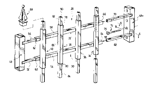
Figure 5 is an exploded view of the window bar guard system
of Figure l;
Figure 6 is a section along the lines 6-6 o~ Figure 5;
; ~?I`,-
- .
~. ~ . ,,, A
~t7~3~
Fiyure 7 illustrates another embodiment according to the
invention for the window bar guard system;
Figures 8 and 9 illustrate different embodiments for
mounting of the window bar system to structural portions of a
building which defines the window opening;
Figure 10 shows the pivotal action of the window bar yuard
system having a lock arrangement for retaining the bar guard
system in the closed position;
Figure 11 is a perspective view of the inside of the
locking system of Figure 10;
Figure 12 is a perspective view of an upper portion of the
bar guard securement device; and
Figures 13 and 14 are rear plan views of the lock system of
Figure 11 showing the locked and unlocked positions.
DETAILED DESCRIPTIo~ c~ D EMBODIMENTS
Figure 1 illustrates the use of the window bar guard
system, according to this invention, on a window commonly found
in residential and commercial buildings. According to a
preferred embodiment, the bar guard system is particularly
adapted for use on basement windows in the building wall 10
adjacent ground level 12. It is appreciated that a majority of
the break-ins to residence and commercial buildings is through
basement or ground level wind~ws at the rear of the building.
Tha window 14 has an opening 16 defined by structural portions or
edges 18, 20, 22 and 24 of the building. These structural
portions may be concrete in which the window frame 26 is set or
they may be of wood which constitutes additional parts of the
window frame.
The bar guard system 28, according to this invention, is
installed in the window opening 16 to discourage breaking and
entry through the window. The bar guard system 28 comprises a
first set of spaced-apart parallel bar assemblies 30 and 32. In
addition, the grillwork 28 comprises a second set of spaced-apart
parallel bar assemblies 34, 36, 38 and 40. ThesP bar assemblies
extend in a direction essentially perpendicular to the direction
of
-3 ~
~ 7()1. rj;~
the first set of bars and are interconnected to form a grid
pattern. The spacing between the first and second s~t of bar
assemblies is such to prevent human passage between, over or
under the bars and through the window opening 16. The end
portions generally designated 42 and 44 of the first set of bar
assemblies are secured to the bui:Lding or window structural
portions 18 and 20 by securing devices 46 and 48. The securing
devices 46 include a lock 50 which, when unlocked, releases end
portion 42 of the grillwork. The other end portion 44 is
pivotally mounted in securing dev:ice 48 so that with the lock
unlatched, the grill may be swung open to allow cleaning of the
window and/or replacement. The lock 50 is of a type which is not
easily pilfered to thwart burglars attempting to pick the lock
and gain entry. Furthermore, the lock system is necessary in
most residential areas due to fire reyulations which require that
the bars can be swung open to permit exit through the window in
the event of fire.
Referring to Figure 5, an alternative to the releasable bar
grillwork mounting device 46 is shown in association with the
grating 28. It is appreciated that some of the windows in a room
may be protected by a grillwork which is permanently secured in
place. Instead of releasable securing device 46, a permanent
device 48a is used which is similar to device 48. In this
embodiment, it is identical since inverting unit 48 provides unit
48a.
The system, according to this învention, is devised in a
manner to readily facilitate installation of the bar guard
system by the householder. Sinc~ residential homes have a
variety of window sizes, it is also necessary to reduce the
number of stack items which must be sold to accommodate these
varying window sizes. This is accomplished by the provision in
the first set of bar assemblies 30 and 32 of telescopic portions
provided by an inner tubular bar 52 telescoped within the outer
tubular bar 54 and similarly with the second bar assembly, the
inner tubular bar 56 is telescoped within the outer tubular
, ;~,
1,~ ~j.''~
,
"';.'.
' ,
'. ,
3l~'7~5~
bar 58. The telescopic arrangement for the bar assemblies 30 and
32 of the first set may be provided at a first end 60 and 62 of
bar assemblies 30 and 32 and optionally at a second end 64 and 66
of the same bar assemblies. In the optional circumstance,
additional tubular bar 68 is telescoped within the outer tubular
bar 54 and tubular bar 70 is tele~scoped within the tubular bar
58. ~he inner tubular bars 52 and 56 and correspondingly with
those of 68 and 70 cannot be extended beyond the respective ends
60 and 62 and 64 and 66 of the outer bars 54 and 58 distances
which exceed approximately the distance between adjacent vertical
bar assemblies 34 and 36. It has been determined that the best
spacing both vertically and horizontal between the ~irst and
second bar assemblies is approximately eight inches. An opening
in excess of this size can make it easier for a burglar to
manipulate either the window or the bar guard system and force
entry. It is appreciated, hcwever, that there are exceptions to
this, such as with respect to the irregular shaped window as
shown in Figure 7 to be discussed.
The first set-of bar assemblies are retractable and
extensible to fit the window size opening within the operative
range of extending either or both of the extensible inner tubular
portions of the first set of bar assemblies. With the first set
of bar assemblies extended to reach the structural portions 18
and 20 of the building, the securing devices 48 and 48a may be
secured to the building wall portions. According to this
embodiment, non-removable fasteners 72 are used which extend
through apertures 74 in the respective retaining devices 48 and
48a. The non-removable fasteners 72 consist of a screw threaded
portion 64 and a case hardened head portion 76 having a one-way
drive slot 78 ~ormed therein. ~y way of the one-way drive slot,
it is understood that a screwdriver may be used to screw the
fastener 72 into the building wall portion. However, the head is
formed with camming faces adjacent the slot which will not allow
the screwdriver to obtain a grip on the head slot when rotated in
the removal direction. Thus as shown in
~l~'7~
Figure 6, the non-removable fastener 72 is threaded into the
building wall portion 18 and the head 76 is countersunk in the
aperture 74 of the retaining device 48a to ensure that the head
76 cannot be grasped with pliers or the like to attempt removal.
It is appreciated that the fastener 72 may be used in conjunction
with an expandable plug sunk in the wall for setting the fastener
72 therein should the fastener be formed of concrete or materials
other than wood which cannot be easily penetrated by common wood
screws.
According to this preferred embodiment, the second set of
bar assemblies 3~, 36, 38 and 40 may include extensible
portions. For example with bar assembly 38, it may have at its
upper and lower ends 78 and 80 inner tubular bars 82 and 84
telescoped in the outer bar portion 86. This arrangement for the
second set of bars provides fox adjustment in the direction of
the second set of bars to fill the gaps above and below the first
set of bars. Pointed elements 88 may be secured to the upper
portions 90 of the inner extensible bars 82.
With the grillwork 28 assembled and all extensible inner
bars located within the outer bars, the securing devices 48 and
48a or 46 and 48 of Figure 1 are secured against the building
wall portions. For purposes of installing the bar grating, the
system is essentially self-supporting due to the telescopic
relationship of the inner and outer bars for the ~irst set. As
to the second set of bars, care has to be exercised with respect
to the lower inner bars 84 to ensure that they are in place when
the grill bar system is installed in the window opening. With
reference to Figure 3, an exemplary telescopic relationship of an
outer bar 54 and inner tubular bar 52 is shown. The tubular bars
52 and 54 may be of a variety of cross-sections, although
according to this embodiment for reasons of ornamental appeal and
strength, the interfitting tubular bars are rectangular in
cross-section.
. .
~ .
1.;~ 7(3 ~ rj~
rrhe bars may be formed of a variety of rigid
break resistant materials, such as plastics which
include glass relnforced plastics and Nylon (trademark)
and metals which include alumlnum alloys and mild steel.
The telescoping bars may be permanently secured together
in a variety of ways which provide an interconnection
between the tubular bars wh:ich is not readily broken by
prying the grillwork with crowbars and the like.
Adjacent wall portions of the telescoping tubular bars
may be permanently secured by use of rivets which can be
inserted through a bore dri:Lled through ad~acent wall
portions of telescoping bars. The rivet is of the type
which is secured in place by way of a special tool for
crimping the rivet in-ternally o~ the tube bars. With
glass reinforced plastics, such as acrylic fiberglass
compositions and nylon, the mating tubular bars may be
secured with an appropriate adhesive which resists the
environmental elements and which does not fail under
pressure. The principal requiremen-t in securing the
tubular telescoping bars is that the handy man or
householder is able to attend to the securing.
According to a feature of this invention, a
device is provided which the householder and handy man
can use to fix and permanently secure the relative
positions of the telescoping bars. In this embodiment,
the bars are formed of a metal which can be pierced,
such as a structural grade of aluminum alloy or mild
cold rolled steel. The piercing device 92 consists of a
rigid clamp having a base 94 and upstanding opposing
walls 96 and 98. The piercing device 92 may be formed
of a high tensile steel. Upstanding wall 98 includes a
threaded aperture 100 which is shown in Figure 4. A
bolt 102 is threaded into the aperture and has a case
hardened conical shaped portion 104 for piercing the
metal of the inner and outer bars 52 and 54. The bolt
102 includes a head portion 106 which can be engaged by
a wrench. The piercing device 92 is positioned over the
overlapping area of the inner and outer tubular bars 52
and 54 and placed against the base 94, as shown in
s~p
, . ..
~ ~ 7 ~ ~'3~
Figure 4. By threadiny the bolt 102 inwardly, the conical
portion 104 pierces the adjacent overlapping wall portions 54a
and 52a. By piercing the overlapping portions 52a and 54a of the
telescoped tubular bars, crimped portions 108 and 110 are formed
in the adjacent walls. Due to the piercing device 104 beiny
conical, the circular opening defined hy crimped portions 10~ and
110 permanently secures the position of the inner bar 52 relative
to the outer bar 5~. It has been determined that this type o~
interconnection can withstand considerable forces exerted on the
grillwork with a crowbar without failing. Upon piercing and
thereby crimping the first set of bar assemblies at their
respective en~ portions 60, 62, 64 and 66 of Figure 5, the
customized window grate is prepared which permanently spans the
window opening 16.
The second set of bar assemblies, in the event that they
have telescoping members are similarly secured. As shown in
Figure 2, the inner tubular bar 82 is secured to the outer bar 86
by crimping at 112. The other inner tubular bar 84 is crimped at
114 to the outer tubular bar 86. In this manner, the positions
of the upper and lower inner tubular bars 82 and 84 are fixed to
properly fill the window opening 16. In view of the telescopic
nature for both the first and second set of bar assemblies, the
outer bars 86 o~ the second set are welded to the outer bars of
the first set 54 and 58. According to this embodiment, the
welding attachment is, for example, in the form of fillet welds
116.
As explained with respect to the shape of the sections of
the tubular bars for purposes of strength and ornamentation,
they are, according to this pr~ferred embodiment, rectangular.
It is appreciated, however, that the telescoping tubular bars may
be of a variety of shapes, such as oval, circular or convoluted
for purposes of additional structural strength and/or
ornamentation. In the event that the piercing device 92 is used
in permanently securing the telescoping portions together, the
shape of the bars is selected to provide a
,.. .
... .
7(l~lrj~
surface through which the pierciny device may extend. Preferably
the telescoping tubular bars include adjacent planar wall
portions extending along the respective inner and outer bars to
provide a face through which the piercing device can be inserted.
With reference to Figure 7, irregular shaped window
openings 118 are readily accommodated by the window bar grill
system according to this invention. The first set of
spaced-apart bar assemblies 30 and 32 remain essentially the
same. Their end portions 42 and 44 are secured by the respective
retaininy devices 48 and 48a to the opposing building structural
portions 120 and 122 which dePined opposing edge.s of the window
opening 124. The second set of bar assemblies include inner
extensible portions 82 which can be extended to varying heights
to Eill the space of the window opening 124 above the horizontal
bar 32. By use o~ the piercing device 92, khe arcuate building
structural portion 126 is filled by varying heights of the inner
extensible portions 82 of the second set of tubular telescopic
members.
As shown in Figures 8 and 9 by way of pivotal connection of
the sacuring devices 48 and 48a to the end portions 42 and 44 of
the bar grill system, the securing devices may be located in a
variety of orientations against varying slopes of the building
structure 128 and 130 defininy opposing edges o~ the window
opening 132. In the embodiment of Figure 8, the securing
devices 48 and 48a are secured to the opposing wall portions 128a
and 130a, whereas in Figure 9 the securing devices 48 and 48a are
pivoted so as to be fa~tened to the exterior wall portions 128b
and 13Ob of the building structure.
As noted with respect to Figure 1, one of the securing
devices may have a lock as at 50 in securing member 46. A unique
key 134 may be used by the householder or owner of the building
to release the lock and allow outward swinging of the bar guard
system 2~ in the direction of arrow 136 to the dotted position at.
28b. The securing device 48 is formed in a manner to permit
complete outward swinging of the bar guard system
,~
~;
;~
;.,
1.2'7~5~
1],
-to the posltion 28b. In the event oE fire, the
householder may use a key located near the interior of
the window opening 132 to permit unlocking of the bar
guard system and permit immediate exit through the
window.
The pivotal connection of the end portion 42 and
44 to the securing devices 'L8 and 48a is shown in Figure
12. For example, securing clevice 48 has the end portion
44 of the bar arrangement 32 pivotally connected
internally of the metal enclosure for the securing
device. The metal enclosure, according to this
embodiment, consists of an outer wall 138 and depending
slde walls 140 and 142. The ends o-f the enclosure ~8
are enclosed by end walls 144. An aperture 146 is
formed in the enclosure 48. The end portion 44 of the
bar 32 is inserted through the aperture 146 to interior
of the enclosure 48. The end portion 44 has an aperture
148 formed therein which extends through opposing wall
portions 150 and 152 of the inner tubular member 56. A
pin 154 is placed through the aperture 148 and then
secured to the interior walls of the enclosure 48 by
weld 156. This arrangement thereby permanently secures
the end portion 44 of the bar guard system wi~hin the
enclosure to preclude unhinging of the bar guard system
from the enclosure of the securing device 48. The
aperture 146 is formed to extend through the outer wall
138 and side wall 142 to permit pivotal movement or
hinging of the bar guard in the manner shown in Figure
10 .
The lock system for the securing device 46 has a
similar enclosure as with securing device 48. The
enclosure is of metal having outer wall 154, opposing
side walls 156 and 158 and upper and lower end walls
160. The lock 50 has a barrel portion 162 into which
the key is inserted through the exterior in the manner
shown in Figure 10. The barrel has secured thereto a
forked member 164 and a spacer disc 166 secured by nut
168. The barrel 162 is secured to the wall 154 by way
':,' ' , :
~ '"', . ~:,
. . .
1~'7~:~5;~
~,~
of a U-shaped cllp 171 which is only partly shown in
Figure 11.
Fiyures 13 and 14 illustrate the action of the
Eorked member 164 moving the slide 170 up and down in
the direction of arrow 172. Ey inserting the key 13
into the lock 50, it is possible to swing the forked
member 164 in the direction of arrow 174. With the
forked member 164 in the position shown in Figure 13,
the slide 170 is in its uppermost position as supported
by leg 176 of -the forked member 164 in opening 182. The
washer 166 is eccen-trically mounted with respect to the
axis 178 of the barre]. of the lock. The washer 166 has
.its central axis 180 offset laterally of the lock barrel
axis 178~ This resu].ts in the washer 166 moviny the
slide 170 over against the interior portion of the wall
158.
To lock the system, the key 134 is rotated to
swing the fork member 164 in the direction of arrow 174.
In swinging the fork member 164 downwardly, -the leg 186
is inserted in opening 184 to control the downward
movement of the slide 170 to thereby lock up the grate
end portion 44 in the retaining device 46.
With reference to Figure 11, the respective
inner bars 68 and 70 of the end portion 42 of the bar
guard system are inserted through the apertures 188 and
190 of the metal enclosure. The washer 166 in moving
the slide 170 against the wall portion 158 assists in
aligning the respective slide pins 192 and 194 with the
apertures 196 and 198 in the respective end portions of
the inner tubular bars 68 and 70. With the pins 192 and
194 aligned with the apertures 196 and 198, the key is
turned by rotating the barrel in the direction of arrow
174 of Figure 14 to pass the pins through the apertures
to lock the end portion 42 of the bar guard system in
the retaining device ~6. As the pins are passing
downwardly through the apertures, increasing play
developes in the movement o~ the slide 170 due to the
eccentric mounting of the washer 166. As shown in
Figure 14, when the slide is in its lowermost position,
" ' i i
' ~ ~ " ~ "i: :''
. . .
~ 7~
a considerable space 200 is developed between the slide
and the wall 15~ to allow the pin portions 192 and 19
to move laterally whatever amount is needed to
accommodate manufacturing tolerances in locating the
apertures 196 and 19~ in the end portions of the inner
tube 68 and 70.
The apertures 188 and 190 are formed in the
outer wall portion 154 and side wall portion 158 of the
enclosure. The securing device 46 is always attached to
the building structural port:ion .in a manner to ensure
that when the lock is released and the slide moved to
its uppermost position, the bar end portions 68 and 70
can be swung outwardly of the enclosure by passing
through the apertures 188 and 190 as the other end of
the yrillwork is pi.voted about the other securing device
48. Due to the advantageous structure of pivotally
mounting the securing devices 46 and 48 to the
respective ends of the grillwork, the installer is
assured of, in one way or another, positioning the
locking enclosure 46 in a manner to permit the grillwork
end portions to be swung inwardly and outwardly of the
enclosure.
The window bar guard system, according to this
invention, may be readily installed by the householder
without requiring elaborate tools. Furthermore, it is
appreciated that, according to a preferred embodiment,
the piercing of the telescopic bar portions permanently
secures them one relative to the other.
Although preferred embodiments of the invention
are described herein in detail, it will be understood by
one skilled in the art that variations may be made
thereto without departing from the spirit of the
invention or the scope of the appended claims.
:.~
:. :
" ~
: . ..
. ." ~ . .
.
; ~ ,