Note: Descriptions are shown in the official language in which they were submitted.
~27~3~3
~2839-965
The present invention rela~es ~o tensioniny devices for
drlve systems that include flexible dri~e elements such as dri~e
chains and drive bel~s.
The present invention is adapted for use with a
conventional drive system in which a driven sprocket and a drlve
sprocket are connected by a flexible drive element such a a drive
chaln. In such an arrangement, it is well known that the proper
functioning of the drive system and the operating life of the
drive chain can be signifi~an~ly enhancad by main~aining the two
drive chain runs between the sprockets in tension such that
significant sl~ck does not occur in either run. One meal~s of
providing such tension is to resiliently bias the sprockets away
from one another. However, a more common and typically more
convenient arrangement is to provide a tensioning devica that
biases one or both drive chain runs inward towards the other run
at a point intermediate the sprockets. A number o~ example~ o~
this lat~er type of tensloning device are disclosed in the prior
art. However~ in the great majority of prior tensioning devices,
the tensioning device is adapted to operate in a particular drive
s~stem, e.g., to operate with a ~iven arrangement o~ sprockets and
drive chain.
One result o~ the ~act that prior tensioning devices
have been adapted fo.r specific applications is that in essentially
all cases, prior tensioning devices have been mounted or secured
to a ~upport that i~ flxed with respect to the sprocket axles.
Through u~e of such a support arrangement, the po~i~ion of ~he
tensioniny device between the sprockets can be controlled, ~o
~3
7~38~
6283~-g6
maintain the tensionlng device at the optimum position. The use
of fixecl supports has been viewed as especially important for
tensionlng devices adap~ed to opera~e wi~h sprocket~ ~hat are or
may be horizontally positioned with respect to one another.
la
~27g~3~3~
-2- 2839-965
In such a horizontal arrangement, the weight of the tensioning
device does not affect its position, i.e., the position of the
tensioning device between the sprockets is not in any way controlled
by yravity acting on the tensioning device.
A further feature o-f essentially all prior art tensioning
devices is that in such devices, the surfaces contacting the two
runs of drive chain and urging them inward have either been fixed
in position with respect -to one another, or resiliently biased
towards one another by springs or similar means. A disadvantage of
the resilient biasing technique is that it adds complexity to the
tensioning device, and the resilient means are themselves subject
to wear over time. Tensioning devices having fixed distances
between their contact surfaces cannot be adiusted as -the chain
experiences increased wear. Thus, the tensioning Eorce provided by
the device decreases over time, at least in those arrangements
where the sprockets are horizontally positioned with respect to one
another. A further disadvantage of a fixed distance between con-
tact surfaces is that the tensioning device cannot be used with
different sized sprockets.
Summary of the Invention
The present invention provides a tensioning device that
overcornes a number of the limitations of prior tensioning devices.
The tensioning device of the present invention comprises a first
tensioning member having first contact surface for contacting the
drive element; a second tensioning member having second contact
surface for contacting the drive element, the first and second con-
tact surfaces being stationary with respec-t to the respective
tensioning member, positioning means Eor securing the first and
B
~2~38~t~
62~39-965
second tensioning members to one another, the positioning means
comprlsing at least one connectin0 member extendiny between the
1rst and second tensioning me~bers, the connectln~ membex
securing the tensioning members ln spaced relationship to one
anothe~ ~ith the ~lrs~ and second contact ~lr~ace~ facing one
another and spaced apart by a distance suffi.clent ~o permi~ ~irst
an~ second runs of the drive el~m~nt to pass between the
tensioning mem~ers ln contact with the flrst and second contact
surfaces, respectively, and ~he connecting member including a
plurality of openings, at least one tensioning member including a
projection adapted to pass through one of said openings in the
connecting member for connecting the tensioning member to the
connectiny member to thereby permit adjustment o~ the spacing
between the contact surfaces by permitting at lea~t one tensioning
member to be secured to the connectlng member at a plurality of
positions; whereby the positionlng means holds the tensioning
members a fixed distance from one another during operation of the
drive system, such that when the tensioning device is in contact
only with the drive element, the tensioning device can respond to
fluctuations in load on the drlve element by moviny in a direction
parallel to the drive element at the points of contact between the
drive element and the tensioning members.
The lnven~ion also provides a tensioning device ~or a
drive system having a flexible drlve element, the tensioning
device comprisiny, a first tensioning member having a flrst
contact surface; a second tensioning ~ember having a second
con~act surface; positioning means for sec~rlny the first and
D
~27~
62~3g-965
second tensioning members a selected distance away from one
another such that the firs~ and second contact sur~aces are spac~d
apa.rt from and faciny one another, the positioning means including
means ~or ad justing the spaci.ng between the con~act sur~aces to
therehy ad~ust the tensioning device so as l:o cau~e the tensionlng
device
3a
,.. ~... .
:'' ','"'''~' ',' " ~ .
~7~30
36
~r-- 62839-965
to apply a suitable tensioning force to the drive element, the
positioni.ng means including a ratchet-like mechanism arranged such
that the force required to move the tensioning members toward one
another is smaller than -the force required to move the tensioning
members away from one another.
In a preferred arrangement, the positioning means includes
first and second connecting members, each connecting member extend-
ing between and secured to the first and second tensioning members.
The connecting members are spaced apart by a distance sufficient to
permit the drive element to pass between the connecting members.
Preferably, at least one of the tensioning members can be en-tirely
disengaged from the connecting members. Another preferred feature
is that the connecting member is elongated along an axis extending
between the tensioning members, and torsionally compliant along
such axis, such that the tensioning members can ro-tate with respect
to one another about such axis, in response to misalignment between
the first and second runs of the drive element.
In one preferred embodiment, the posltloning means
includes a ratchet-like mechanism arranged such that the force
required to move the tensioning members toward one another is
smaller than the force required to move the tensioning members
away from one another. In a second preEerred embodiment, each
connecting member includes a series of openings spaced along its
length, to permit the tensioning members to be positioned at a
selected distance from one another. In another embodiment, each
connecting member includes a series of closely spaced, crosswise
extending serrations, and each tensioning member includes a fasten-
lng member having a blade-like edge and means for forcing the edge
~7@~38~)
--~c --
~b-- 62839-965
agains-t the connecting member, to secure the tensioning member -to
the connecting member. In another arrangement, each tensioning
member comprises one or more rollers, the contact means comprising
the outer circumferential surfaces of said rollers. The tensioning
member also includes means for mounting each roller such that the
roller is free to rotate with respect to the positioning means in
response to relative movement between the positioning means and the
drive element in contact with the outer circumferential surface of
the roller. In a further embodiment, at least one tensioning
member includes a body having one or more cylindrical openings
within which one or more cylindrical rollers are positioned, such
that the contact means comprises the outer circumferential surface
of each roller.
Brief Description of the Drawings
FIGURE 1 is a side elevational view of one embodiment of
the tensioning device of the present invention used in connection
with a drive chain;
FIGURE 2 is a perspective view of -the tensioning device
of FIGURE 1;
; .:.
.'
~703
--4--
FIGURE ~ i3 Q cros~section~l vlew taken along line 3--3 o~ FIG
URE l;
FIGURE 4 is an exploded perspective view of the tensionlng devlce
of FIGURE 1;
FIGURE 5 is a perspective view of a second preferred embodiment
of the invention;
FIGURE 6 is a partial perspective view of a third preferred
embodiment of the present invention;
FIGIJRE 7 is a side elevational view OI a fourth preferred embodi-
ment of the pre~ent invention;
FIGURE 8 is an end e~evational view, part1y in cross section, of the
embodiment of ~IGURE 7;
FIGURE ~ is a side elevational view, partly in cross section, of a
fifth preferred embodiment of the present invention; and
FIGURE 10 is an end elevational view of the embodiment of
~lGVRE 9.
Detailed Description of the Drawing~
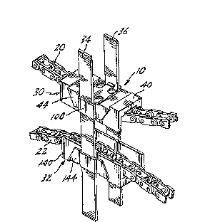
FIGURES 1 ~nd 2 ilIustrate tensioning device 10 of the present
invention used in connection with a conventional drive system that includes
sprockets 12 and 14 interconnected by drive chain 16. An upper run 20 of the
drive chain extends between the upper sid~ of spro~kets 12 and 14, and lower
run 22 exten~; between the lower sides of the sprockets. Depending upon which
of sprockets 12 and 14 is driven and upon the direction of such drive, either
upper run 20 or lower r~ 22 will be placed under tension by the dlqvin~
mechanism. However9 in the absence of the $ensioning device of the present
invention, the other run will be ~lack~ thereby increasing chain wear and
ultimately leading to the possihility that the chain will come off one of the
sprockets.
Tensioning device 10 comprises upper assembly 30 and lower
assembly 3a intercoMected by strapæ 34 and 36. Upper aæembly 30 includes
block 40 that engages upper run 20, and lower assembly 32 includes block 140
that engages lower run 22. The blocks ~re connected to the straps by ratchet-
like arrangements, described below, such th~t the blocks can be moved toward
one another upon applicaffon of a comparatively small foPce, but c~n be moved
aw~y ~rom one another or~y upon ap~aication cf Q comparaffvely large force7 or
by use o~ a separate tool. Thus during operaffon of the tensior~ng device,
strap6 34 and 36 hold th0 upper and lower assemblies in fixed posiUon with
respect to one another, despi$e the tension exerted by drive chain 16 tending to
A
~ ~7~38~
move bloclcs 40 and 140 away from one another. However9 the tensioning device
of the present invention can readily be ad~usted to decre~se the separation
between the blocl~ during the life of the drive chain, to take up ~ack caused byincreasing drive chain wear. Furthermore, when the tensioning device of the
present invention is installed on a drive chain or other nexible drive rneans, the
distance between the blocks can be varied over a wide range, and the tensioning
device can therefore bP used for a wide range of spr~cket sizes and distances
between the upper and lower runs.
A further important feature OI the present invention is that it is
capable of operation without any means for positioning the tensioning device on
runs 20 and 22 between the sprockets. This is true for all positions of the
sprockets with respect to one another, including the horizontal position shown in
FIGURE 1. It is also true regarclless of which of sprockets 12 and 14 is the drive
sprocket and reg~rdless of the direction of rotaffon of the sprockets. The
tensioning device of the present invention therefore proYides a device having a
wide range of applications to different drive sysl:ems. It is to be understood that
the present invention is also applicable to drive systems in which the flexible
drive element comprises an O-ring, a V-belt or other drive belt, A rope, a bead
chain, or any other flexlble drive element.
In a convention&l tensioning arrangement, the upper and lower
assemblies or their equivalents are resiliently mounted to an external structuresuch that they can move in directions normal to the drive element, to
accommodate the inevitable fluctuations in load or tension during operation of
the drive system. By contrast, in the tensiorung device of the present invention,
the tensioning members are secured a fixed distance from one another, but the
tensioning device can move along the drive element to accommodate fluctua-
tions. This moYement ~ong the drive element provides n very effective
vibration and shock absorber mechanism. In addition, unlike a conventional
arrangement, shock and vibraffon are not transmitted through the tensioning
device to an external structure.
Referring now principally to FIGURE 4, upper assembly 30 com-
prises block 40, blade member 42, and clip 44 Similarly, lower assembly 32
comprises block 140, blade rnember 142 and clip 144. In the preferred embodi-
ment illustrated in ~IGURES 1-4, the elements of the upper and lower assemblies
are identic~l to one another, and a numbering scheme is used in which elements
of the lower assembly are assigned reference numerals 100 greater than the
re~erence numerals of the corresponding elements of the upper assembly. Where
the context permits, reference in the following description to an element of one
7~8~
of assemblies 30 and 32 sha~l be understood as also referring to the corresponding
element in the other assembly.
Block 40 includ~ center portion 46 frorn wh~ch identIcal ~id~
walls ~8 and 50 extend to form U-shaped chQnnel 52. The side of center
portion 46 that faces inw~rdly into channel 52 comprises contact surface 58
flanked by rails 54 and 560 The rails and contact sur~ace have a common arcuate
shape, and the height of the rails above the contact surface is constant, to
thereby form convex groove SO that extends the full len~fth of channel 52. Upperrun 20 of drive chain 16 rides in groove 60, as best indicated in FIGURE 3.
Rails 54 and 56 keep the sides of chain 16 away flom sidewa~ls 48 and 50,
thereby minimizing friction ~tween the drive chain and the block.
The swrface oî center portion 46 that faces away frorn channel 52
includes projections 62 and 64 at opp~-site longitudinal ends of the center portion9
and mounting surface 66 between the projectionsO Mounting surface 66 includes
lateral edges 68 and 70. The inner edges of projections 62 and 64 include lips 72
and 74 that are sliahtly overhanging with respect to the adjacent portions of
mounting surf ace 68.
Blade member 42 includes end sections 80 and ~2 and center
section 84. Center section 84 includes laterally extending blades 86 and 88. Theouter edges o~ blades 86 and 88 include tips 90 and 92 that are angled slightly out
of the plane of the blade member in a direction away from mounting sur~ace 66
and block 40. The function o~ blades 86 and 88 is described below.
Clip 44 includes side pieces 100 and 102 interconnected by top
pieces 104 and 106. Side piece 100 comprises center portion 108 that is shaped
to form a shallow, inwar~y facing, U-shaped groove. Center portion 108 is
flanked by end portior~s 110 and 112. Similarly, side piece 102 compiises centerportion 114 flanked by end portions 116 and 118, center portion 114 also being
shaped to form a shallow, inwardly facing, U-shaped groove. Top piece 104
interconnects end portions 110 and 116, and top piece 106 interconnects end
portions 112 and 118
Blade members 42 and 142 and clip6 44 and 144 are preIerably
constructed of a metal such as steel. Blocks 4û and 140 and straps 34 and 36 arepreferably constructed from a low friction material such as ~d~ra high molec~ar
weigm polyethylene (UHMW). A low-friction material available from du Pont
under the trademark NYI.ONTRON is also slfitable. Upper assembly 30 is Iormed
by placing blade member 42 on mounting surface 66, and then forcing clip 44
over the top and sides of block 40 such that the longitudinal e~ges of top
piece3 104 and 106 are retained under lip~ 72 and 74 respectively. The
(138V
longitudinal extent of blade member 4~ i~ slightly less than the distance between
lips 72 and 74. Similasly, the lateral ~xtent of end sections 80 and 82 are slightly
less thAn the lateral extent ~ the block. However, tlpS 90 and ~2 e~tend ~ghtly
over respective edges 68 and 70, as best illustrated in FIGURE 3. The form~tlon
of lower assembly 32 is iden~sic~l to that of the upper assembly. Clie6 44 and 144
are formed such that strap~ 34 and 36 can be inserted in the slots formed by thecenter portions of the clips and the adjacent sidewalls of the corresponding
blocks. For example, the upper end of strap 34 may be inserted through the slot
formed by center portion 108 of clip 44 and the adjacent lateral surf~ce of
block 40, ~s shown in FIGURES ~ and 3. When strap 34 is so inserted, the strap
makes contact with tip 90, as illustrated in FIGURE 3. Because tip 90 is angled
slightly upward and away from block 40, the res~dt is a ratchet-like arrangementin which strap 34 can be moved upward in the slot upon app~ication of a
comparatively small force, but can be moved downward in the slot only upon
application of a large force, or by manipulaffon of blade 86 by a separate tool.The U-shaped openings between center section 84 and end sections 80 and 82 of
blade member 42 permit insertion of a screwdriver or other toc71 under the
blades, such that the blades can be r~ised above mounting swrface 66 to move
tip 90 or 92 upward and away fsom the block. Such upw~rd movement of the
bl~de tips disengages the tips from the straps, to thereby permit the straps to be
moved downwardLy with respect to the upper assembly. The connections
between lower assembly 32 and straps 34 and 36 Are identical to that described
for the upper assembly.
When the tensioning device of the present invention is initially
applied to a drive chain, drive belt or other flexible drive member, straps 34 and
36 are first inserted a short distance into one of the assemblies, such as the
upper assembly, and the parffally-Iormed tensioning device comprising the upper
assembly and str~ps is then placed over one of the runs ~ the drive chain. The
other assembly is then placed on the opposite side of the other drive chain run
and the straps are inserted into that assembly. The upper and lower assemblie~
are then manually moved closer together until the tensioning device exerts an
appropriate force on the drive ch~in runs~ When the ~ive sy-stem is in operation,
the drive chaln runs pass throwgh grooves 60 and 160 of block~ 40 and 140,
respectively. When the bloclcs ~re spaced an appropriate distance from one
anothe~, the tensioning device maintains a fixed avernge position between the
sprockets d~ing operation of the drive system, without the use o~ any auxiliary
means to position the tensioning device with respect to the sprockets. The best
sepnr~tion of the blocks m~y readily be determined by initially setting the block~;
...... , ~
~27(~38(3
--8--
Q comparativeay large distance apart, and then oper~ting the d~ive system and
gradually decreasing the block separation until the optlmum position i5 found.
As the drive syst0m experience~ wear over a comparaUve~y long tlme period,
drive ehain 1~ will exhibit increased ~mount of slack. Adjustment tor such slackcan again be readily made by manually ~orcing the blocks together, ag~in until
the optimum position is found. Removal of the tensioning device from the drive
chain can best be accomplished by me~ o~ a screwdriver or the like, to ~orce
blade tips aw~y from the straps, as described above.
A second preferred embodiment of the tensioning device of the
present invention is illustrated in FIGURE 5. This embodiment ~omprises upper
assembly 170 and lower assembly 172 interconnected by strap~ 174 and 176.
Straps 174 and 176 each include a series of equal sized, vertically spaced
openings 178. Upper assembly 17~ and lower assembly 172 each includes
block 180, U-shaped bracket 182 and a pRir of plates 184 positioned on opposite
sides of the assembly. Each block 180 may have a shape and composition similar
to that of blocks 40 and 140 of FIGURES 1-4. Brackets 182 are fastened to their
respective blocks by any suitable means such as screws or rivets~ Threaded
shafts 186 extend laterally from either side vf brackets 182 (o~y two sh~fts 186shown in ~IGURE 5). Shafts 186 are dimensioned so that they can pass through
openings 178 in straps 174 and 176. Each plate 184 includes a centrally
posiffoned opening 188 through which shafts 186 can also pass. Washers 190 and
wing nuts 192 are provided for securing the plates and straps to brackets 182.
In order to secure upper assembly 17n and lower assembly 172 to
one another at a predetermined spacing from one another, nuts 192, washers 190
and plates 188 are removed from the assembly, as shown in the upper right
portion of FIGURE 5, and shafts 186 are positioned in the app~opriate open-
ings 178. The plates, washers and nuts are then secured together, as shown in
the lower portion of FIGURE 5, to produoe a complete tensior~ng device
assembly.
Ur~ike the embodiment of FIGURES 1-4, the embodiment of ~1~
URE 5 does not include a ratchet-like mechanism for securing the upper ~nd
lower assemblies to the straps. However the ter~ioning device of FIGURE 5 can
readily be adju~ted to decrease or increase the separation between the blocks
d~ing the life of the drive chain, for example, to take up slack caused by
increasing drive chain we0r. Like the embodiment of FIGURES 1-4, the
embod~ment of ~IGUE~E 5 is also cflpable of operation without any means for
positioning the tensiordng deviee to an external struoture. Thi~ i~ true for allpositions o~ the sprockets with respect to one another, and regar(ness ot which of
.~
'
. , .
- 9 -
sprockets 12 and 14 ~ee PI~URE 1) 5~ the drlve sprocket, and regardless of the
direction of rotation of the sprockets.
A third embodi ment ~f the tensiolung device o~ the pre~ent
invention is illustrated in parti~l view in ~lGURE 8. PIGURE 6 illustrat~ upper
assembly 200 sec~ed to straps 204 and 206. Each of the straps includes a series
of closely spaced horizont~l serrations. Upper assembly 200 includes block 210
and bracket 212, the bracket being sec~ed to the block by any suitable means
(not shown) such as by rivets. The lateral sides of block 210 include channels to
accommodate the straps. Threaded shaft 220 extends upwarc~y ~rom
bracket 212, or extends upwardly from block 210 through an opening in brac
ket 212. V-shaped spring met~l clip 222 is p~sitioned between str~ps 204
and 206, and includes a central opening through which shaft 220 extends. The
clip may be secured to the upper assembly via wing nut 224 and one or more
washers. By tightening wing nut 224, clip 222 is forced downward, forcing the
outer, blad~like edges of the clip to bear against the inner, serrated surfaces of
straps 204 and 206, thereby securing the upper assembly to the straps. In
contrast with the embodiment of FIGURE 5, this arrangement permits an
essentia31y continuous adjustment of the position of the upper and lower
~ssembli~; with respect to one another.
A fourth embodiment of the present invention is illustrated in
FIGURES 7 and 8. In this embodiment, a p~ur of generally T-shaped carriers 230
and 232 are positioned in aligned, spaced relationship to one another on opposite
sides of upper run 234 and lower run 236 of ~ drive belt. The upper end 240 of
each carrier includes a pair of laterally spaced openings at which a pair of
respective upper rollers 242 and 244 are secured between the upper ends 240 of
the carriers. Each roller includes a centr~l shaft 246 that is secured between the
carriers by a pair of nuts 248, ~nd an outer, clrcumferenti 1 contact ~leeve 250mounted on the shaft by a suitable be~ring assembly 252. The outer surface of
the upper contact ~leeve is U-s~peds and adapted for contaeffng the drive belt.
As shown in FIGURE 7, rollers 242 and 244 mount the tensioning device on upper
run 234.
Each c~rrier includes downwarc~y depen~ing stem 254 that includes
a series of equal sized, verticslly spaced openings 256. A lower roller 258 is
mounted between the stems at a se~ected pair of openings 256. As sh~wn in the
~igure~, lower roller 258 is ~dapted for contacting lower run 236 o~ the drlve
belt. The distance between lower roller 258 and upper rollers 242 and 244 may
be adjusted by selecting the openin~s 256 between which the lower roller is
mounted. In general, one or more rollers may be used at either (upper or
A
~27~3~C~
-10-
lower) end of the tensioning device. FIGURES 7 And 8 show a pre~erred
arrangement, with a singie roller At one end ~nd a paurality of rollers at the
other end.
A further embodiment of the invention is illustrated in
FIGURES 9-10. This embodiment includes upper assembly 260 ~nd lower a~sem-
bly 262 intercoMected by strapæ 264 and 266. Each strap includ~; ~ series of
equal sized, horizontally spaced openings 268. Each of the upper and lower
assemblies includes bracket 270, block 272 and plate ~74. The upper and lower
assemblies may be secured to the straps by a technique identical or similar to
that shown in FIGURE 5. In the embodiment o~ FIGI~R~S 9-10, each block
includes an embedded triplet of rollers for reducing the friction between the
flexible drive element and the blocks. In particular, referring to the lower
portion of ~lGURE 9, each block includes three oper~ings cut through the block in
a horizontal direction normal to the direction of movement of the fle~ble drive
element. Cylindrical rollers 280-282 ara positioned in the openings, the fit
between the rollers and the block being loose enough to permit the rollers to
readily rotate as a fle~ble drive element passes over them. Thus the contact
sur~aces of the blocks comprise the outer circumferential surfaces of
ro?~ers 280-282. The central roller 281 is preferably positioned ~ligh~y higher
than the end rollers 280 and 282, to match the slight bend that the fle~ble drive
~ement will typically have in passing over the block ~see FlGURES 1, 2 and 7)~
Blocks 272 and rollers 280-282 are preferably composed of a low friction, plastic
mateFial, to mimimiæe heating of the blocks in use.
In all of the described embodiments, the upper and lower assem-
blies are preferably interconnected by straps that are constructed to permit a
certain amount of rotation o~ the assemblies with respect to one another about avertical axis that extends through the upper and lower assemblie~ between the
straps. Thus slight misalignment of the upper and lower runs of the flexible
drive element will be accommodated by misali~nent OI the upper ~nd lower
assemblies, and will not cause increased friction or binding between the drive
element and the assemblies.
While the preferred embodiment of the invention hfls been illus-
trated and described, it should be understood that variations will be apparent to
those skilled in the art. Accordingly, the invention is not to be limited to thespecific embodiments i~ustrated and described, and that the true scope and
spirlt o~ the inverlltion are to be determined by reference to the following c~aims.
1.
`I