Note: Descriptions are shown in the official language in which they were submitted.
Apparatus for severing a web
The present invention relates to an apparatus intended to be
used in connection with a paper or a board manufacturing
machine for severing a web b~ a strip while a jumbo roll is
being produced.
In paper and board manufacturing, it is of primary importance
that the machine can operate as uninterruptedly as possible
without any stoppages. All other paper machine operations are
of a continuous nature except for winding of the fi~ished web.
Breaks in the wind-ng occur during chanqing of the roll and it
is desirable such operation be carried out as quickly as
possible so as not to waste paper and at least to avoid the
need to stop the machine itself. The most difficult stage in
thP roll change is when the wek has to be severed and winding
of a new roll has to be initiated.
For this purpose, many different arrangernents have been
developed, starting from the operatlon in which, whil.st the
jumho rol] w~s being produced, a tear wa~ s~ruck ~t the edge
o~ the weh and at whlch t~Jar th~ weh WOt11~ hOpf!fUlly bre.lk
~tansvers~Ly. S~cur:Lny of l:h~ web ~r~ nd ~ new r~-l drum to
p~?rm~ .Jlly Wa8 attempte~ by, for example, rnaking the
surface of the r~el drum to .some extent adhesive so as to make
the free end of the web adhere to it. In manY cases, howe~7er,
the web starte-l to tear longitudinally and in whlch case there
was no alternative but to stop the machine and tear the
damaged web off both the jumbo roll and the new roll.
To avoid incidents like those mentioned, a web cutting appar-
at~s W2S developed to effect severing of the web across its
whole width. For example, U.S. patent 3,794,25S discloses the
utilization a toothed bl~de in web cuttiny. The apparatus is
also e~uipped with a sp~cific web yuide which, at the cutting
:, :
~ 3~ 3
s-tage raise~ ~h~ web off the surface of a guide roller, at the
same timts constituting a counterpiece of the cutting blade to
ensure the cutting. In this solution, securement prior to
winding of the web around the new reel drum was effected by
applying a g]ue-like layer on the surface o4 the reel drum, to
which layer .the free end of th~i web is bound to adhere.
FI-patents f)9~19 and 69820 disclose equivalent cutting sol-
utions.
U.S. patenk 3,599,8g8 discloses a use of an adhesive tape in
weh cutting, wherein the web is arranged to extend diagonallv
across-the weh and the ends of the adhesive tapt? extend beyond
the edges of the weh. When the web is led in betwetn the new
roll and a rotating roller, which roller also leads the web to
the jumbo roll, the entls of the adheciive tape will adhere
firmly to the new roll. While being held firmlv against the
new roll by ~he adhesive tape and tending to follow the
rotating roller, the web ls cut along the edge of the adhesive
tapts. Furthermorej ano-ther tapts ~s arratlyed btsside said
adhesive tape and at -the leadlng erlcl o it clnd par-tly on top
of the ~trst ildllt~L;lve -tape, SO that said another tapts ~Ic~es not
extend b~voncl thl3 edtlt3 (~ ~ht we~. lt can tht~reby be en3ured
that l:he tralLincJ ~nd o (:he whb Oll the completed jumbo r~
wlll al30 cld?lc~re t o th~ prececlin~ layer o~ tht* web so that
there is no dclnc1er o~ th~ top layer.s of the jumbo roll be-
comlng slack. 'rhe patent also dlscloses 1~he manual disposing
of an adllesive -tape in place on the web with the machlne being
either in operation or s~opped. The pa-tent furthermore dis-
closes tlle posslbility of arranginy for a separate roll to
feed the adhesive t:ape t~ a desired place on the web in the
winding station. Due to the present high machine speecls, the
first two manual methods as presented hereinabove are imprac-
tical, and even the third method is highly uncertain with such
hiqh speed operation. Anvway, it has to be said that the
mechanical method as presented would call for extensive
equipment in the winding station whic'n in any event is of very
restricted space. The equipment would also be very costly.
,
~ t
Another type of tape cutting is presented in GB-patent 1135945
wherein a web is severed by means of a strip tensioned against
the surface of a new roll. Initially, one end of the tape is
fixed with a ],oop on the shaft of an empty reel drum and led
through a spring tab ahead of the rolls and belcw the web,
when viewed downstream relative to web mov~ment. The other end
of the tape is led through two supports to a rotating wheel
the speed of which can be reduced. At this stage, the web runs
between the rotating roll and an empty reel drum a~ove it to a
jumbo roll which i~ suh~tantially on the same le~el horizon-
tally as the rotating roll an~ disposed behind it. As soon as
the jumbo roll has been wound to its full diameter, the tape
will be tensioned so as to loosen it from the spring tab and
force it in between the rotating roll and the empty reel drum.
Since the tape has been attached to the shaft of the reel drum
and its other end to the deceleratable wheel, it tends to
follow the surface of the reel drum, thus cutting the web
which tends to follow the rotating roll downwards. ~ven though
the apparatus functions satisfactorily and is simple, it also
has some shortcomin~s. For eY~ample, the taking of a tape loop
to the sha-Et of an empt,~ reel drum is sometimes a dificulk
and even danger~u~ ta~k bec~use :it has to be ~lone near ast-
~otcltlng r~lls. Th~ manual tap~ l~unching mechanism disclo~
ln ~hi.; prior sp~ci.fi.cation case i,s also inaccurate and calls
~or continuous ~ollow-up of the jumbo roll.
U.S. patent specification 4414258 relates to a turn-up tape
used for severlng a travelling web of paper~ A tape spool is
arranged on one side OL the winder section of the paper ma-
chine. The tape i 5 taken to the other side oE the machine, and
the end of the tape on the reel drum side is made adhesive and
then fed in between the Pope cylinder and reel drum, whereby
one end of the tape adheres to the reel drum and freely winds
around the drum, at the same time cutting the web due to
tensioning of said tape. The tape spool has a braking device
..
~-
,~
, ~. :
~ 3
which maintains a sufficient tension in the tape for cuttiny
the web. In the U.S. patent specification 4414258, there is no
discussion as to how the end of the tape is inserted into the
nip between th~ Pope cylinder and the reel drum. Thus, it is
assumed likely such is inserted manually, which is very
dangerous as one has to stand close to fast-rolling cylinders
and rolls whils-t feeding the tape into a small nip.
It is an ob~ect of the present invention, to provide an appar-
atus which eliminates or minimises the disadvantages and
dangers of the above-mentioned apparatuses. The apparatus
according to the invention is characterized in that it com-
prises a tape feeding device articulated to one side of the
winder, said feeding device being operable to feed the tape in
hetween the Pope cvlinder and reel drum, a stationary guide or
swing guide articulated to the opposite side of the winder,
said guide guiding the winding of the tape around the reel
drum, and a tape cuttina ~pparatus which cuts the tape after
said tape having severed the web. An advantage of the working
principle of the apparatus according to the invention is i-ts
nearly automatic operatlon. The operator needs only to set the
appardtus after each roll chan~ whereaeter it t~kes c~r~! o~
th~ web cuttin~J ~n lt~l own ~n du~ tLme. Other advantclyes are,
~or ~3xampl~ hat the ap~aratus ls ~3~lsy to set and has a
construction that ls simple and reliabl~ in operation.
The invention will be described further, by way of example,
~ith reference to the accompanying drawings, in which
ig 1 is a schematic side view of one half of a severing
apparatus according to the invention;
ig. 2 is a schematic view in the direction of arrow A in
Fig. 1 illustratina a preferred embodiment of a card
holder used in the apparatus;
'3
ig. 3 is a sectional view taken along line B~B of Fig. 1,
illustratinq a preferred embodiment of a tape holder
used in the apparatus;
.
ig. 4 is a schematic illustrat;on of a preferred embodi-
ment of a s~7ing guide and tape cutting device used
in the apparatus and viewed downstream of the ma-
chine; and
iq. 5 is a side view of the device of Fig. 4 viewed from
the left-hand side thereof.
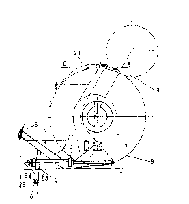
Figure 1 is schematic illustration of a winder of a paper or
board manufacturing machine, which winder receives web,
entering from the left-hand side i.e. fr~m the direction of
arrow C. Figure 1 shows the position in which reel drum 9 has
been lowered and brought into contact with Pope cylinder 8
whereupon the Pope cylinder 8 makes the reel drum 9 rotate the
web remaining between the drurn 9 and cylinder 8. ~ tape feeder
1 in the tape cutting device o~ the invention mainly comprises
a turning arm ~ ha~rin~ drive device 3 (piston~cylinder)~ ~
tape holder ~, a carc~ holder 5 ~t the f311d of the turning arm
2, w:ith a ~princJ clip 6 b~iny mounted at l:he ~nd of ~aid tap~
hold-!r 4. 'rhe turnlncJ axrn 2 Ls articulated to one ~lde of the
win(7r3r ~n~l ~rranged so as t~ turr in the sclme direction as the
rnachine. To the same side of the winder, drive device 3 is
also articulated and one end thereof ~end of the piston rod)
is articulated to the turning arm 2 so as to permit the
turning of the turning arm 2 rom a substantially horizontal
position ~as shown in full-line) to a substantiall~ vertical
position (as shown in broken line). At a distance from the
free end of the turning arm 2 there is secured thereto the
tape holder 4 having one end of which i.e. spring clip 6
remaining somewhat below the card holder 5, when the turning
arm i9 in the vertical position. The card holder S is disposed
at the end of the turning arm 2. As also shown in Fiq. 1, the
articulation point 7 of the turning arm 2 in this embodiment
, . ~ , :
:::
~2~
ls disposed on that vertic~] p]ane which extends throuyh the
shaft (axis3 of the Pope cylinder 8 and at a distance below
the shaft. The efficient length of the turning arm 2 is such
that the card holder 5 extends a little above the shell of the
Pope cylinder 8 when the turning arm ~ is in its vertical
position. In this case the spring clip 6 remains somewhat
below the upper horlzontal plane tangential to tne Pope
cvlinder shell.
Fig. 2 illustrates the structure of the card holder 5 which is
located at the end of the turning arm 2. Card holder 5 com-
prises a pocket 30 made of bent plate material, said pocket
being open in the moving dlrection of the web and towards the
inside of the machine so as to make it possible to insert a
card 31 made of, for irstance, cardboard in the pocket in a
way such that two sides of the card remain totallv olltside the
holder, cf. Fig. 4. The disposition of the holder 5 when the
turning arm 2 is in the vertical position, is substantially
such that the card 31 in the holder 5 projects in-between the
Pope cylinder 8 and the reel drum 9. The card 31 may be
irserted in the pocket 30 of the holder 5 by a lever 33,
mounted on bearings on a shaft 32, being pressec1 at one end
i.e. the one on ~he side of the SprincJ 34, whereby the oppo-
site end Oe the lever 33 .i.f: c~etached from the lower sid~ of
~h0 pockel: 3n to permit l:l1e card 31 to he pushed into the
pocket 30 helow the lever 33.
Fig~ 3 illustrates the spring clip 6 located at the end of the
tape holder 4, said clip 6 comprising a lever ll kiased by a
s~ring lO, which construction forms a loop for a tape 28 to
travel in. While the tape is being stretched, the sprina lO
lengthens and opens a route for the tape to slip off the clip
6.
Fig. 4 presents the parts of the tape cutting device that are
disposed on the other side of the winder i.e. a swing guide 12
swinging vertically across the direction of movement of the
.,:, ,
web an~ a tape cutting device 24. The swing guide 12 comprises
a lengthy frame part 13, at the lower end of which is disposed
a counterweight 14 to balance the guide. The swina guide 12 is
articulated at point 15 to the winder frame so as to enable it
-to pivot between the substantially vertical position and the
inward~ directed horizontal position of the winder in the
direction of the Pope cylinder shaft. Turning of the swing
guide is so balanced that, upon becoming tensioned, the tape
28 is able to turn the guideO On the opposite side of frame 13
to the articulation and secured to the guide 12 at the end of
an arm 16,.there is a shaft 17 on which a tape spool 29 is
disposed (Fig. 5~. The upper part of the fl-ame part 13 is also
equipped with guide loops 18 for the tape and a strip brake 19
between the loops, which brake comprises a bent plate 21, said
plate being mounted on bearings on lugs 20 and di~posed at a
distance from the frame part 13, and having on its middle area
a part 22 substantially parallel with the frame part 13, the
tape travelling between said part 22 and frame park 13. A
braking efCect is accomplished by two spring-loaded adjustable
screws 23 which pre~s the part ~2 ayainst the frarne part 13.
Fig. 5 illustrat~c; ~ t~E~e ~utklncJ devi.ce 2~ which, ~u~k l.i.k~
th~ 3winy gu.i.de 12, 1~ di.sposed extending agcl:inst th~ cl.i.rec~
tlon ~ movement o~ the web and a little before the Pope
cylinder 8. The tape cutting device 24 is adjustably attached
to the winder frame so as to leave the cuttir.g hlade a little
outside of the vertical plane extending through the edge of
the web. The cutting device 24 mainly comprises two cutting
blades 25 positioned in the V-formation in relation to each
other, said blades being secured to a rod 26 so that they can
be turned and being adjustable in the longitudinal direction
of said rod; said rod being correspondingly secured to a
horizontal rod 27 extending in the machine direction and
turnably or pivotally attached to the reel frame.
The working principle of the apparatus in accordance with the
invention utilising the severing of a web by a tape, involves
: . .,
,:
~ t7~3
the fol].owing: The tape 2~ unwinding from a tape spool Z9
disposed on the shaft 17 is threaded through the guide loops
l8 and the strip brake l9 positioned between said loops.
Thereafter, the tape is taXen from the swing gu.ide 12 under
the paper web to the other side of the winder and then
threaded through a loop of the spring clip 6 towards the card
holder 5. Next, the tape is pressed by means of an approprlate
card and two-sided adhesive tape on the piece of cardboard so
that the tape remains between the adhesive tape and the card-
board, and the tape with adhesi.ve tape remains, when seen
downstream, in the left corner of the card with its glue side
upwards. In a position like this, the card is taken to the
card holder 5, and consequentlv the tape runs direct from the
card to the loop of the spring clip 6. Af this stage, as the
turning arm 2 is in its bottom position i.e. substantially
horizontal, the device is ready for operation.
The operation itself takes place as follows. As the paper roll
being wound on the reel drum reaches its full diameter, the
drive device 3, which is most usually a pneurnatic or a hy-
draulic cylinder, receives an impulse causing it to operate
and consequent].v t.urn the turning arm 2 to the upper positior
and thus pushing the er.d of the ca.rd 31 di~qposed in the card
holder S in be~ween khe reel drum 9 anc1 -khe Pope cylinc1er 8 on
the f;he.1~. clrea ~cliac~nt to the weh. T}le rotatincJ rolls draw
l:he carcl In hetween th~m, whexe.~ the uppe:r surface of the
aclh~sive -tape adheres to the ree1. flrl.lm, thus drawing the tape
with it At. th~ 5 stage, the tape becomes stretched and is
pulled loose of the spriny clip 6 of the tape holder 4,
whereby the tape will be free to be wound almost a complete
revolution around the reel drum until it i5 stretched to such
an extent in the cross direction of the winder as to break the
web in a controlled manner. The tension of the tape can be
adjusted to suit every situation of the operation by means of
the swing guide brake. While severing the web, the tape leads
the free end of the web around the reel drum. As soon as the
. :, .. .
,~
.'
. .
~ 3
tape has spirallv wound around the reel drum and cut the web
across its entire wldth, it has travelled so far to the left
~Fiq. ~) that it ls drawn in between the blades of the tape
cutting device 24, which blades cut it off. In this case the
brake 19 holds the end of the tape in place so as to make it
easy to draw said.tape from that position under the web and to
reset and reoperate the device.
t.his staqe, it is worth mentioning that the device as such
is suitable for cutting webs of all widths. Should there be a
need for adjustment, .the tape cutting device 24 is full~y
adjustable, to suit, for instance, a considerably narrower
web, so as to thereby save tape. It is also worth mentioninq
that the balancing of the swing guide 12 ensures the best
possib'e wav of winding the tape around the reel drum.
Further, it is worth mentior.ing that, the above description
discloses only one favourable embodiment of the apparatus of
the invent~on, which is not intended to in any way li.mit the
invention from what i5 presented in the accompan~ing patent
claims. Hence, it is co~pletely possible to make the end of
the tape adhesive .;.n ~ome othe.r wa~. Th~ us~ of th~ ca.rd as
specified hereinabo~e is one rel:~able and ~pproved way. If the
card ls, however, not u~d, the~ fi~ruct~re of the card hol.der S
wl~l. chan~e conF.i.clerc~b.ly. It i5 also pos~ible to fll~ther
~impli~y the device by replacing the swing guide by a simple,
stationary guide roller or equivalent which leads the tape
unwinding from the spool to the feeding device. The most
suitable way of providing the stationary guide is to dispose
it below the tape cutting device in a way that when the tape
is being wound around the reel drum, it gets in between the
blades of the cutting device. Also other equivalent changes
are possible without departing from the concept and scope o~
the invention as claimed.
:. ' :. . .
,
, ,:. ;..
.:: :