Language selection

Search

Patent 1270803 Summary

Third-party information liability

Some of the information on this Web page has been provided by external sources. The Government of Canada is not responsible for the accuracy, reliability or currency of the information supplied by external sources. Users wishing to rely upon this information should consult directly with the source of the information. Content provided by external sources is not subject to official languages, privacy and accessibility requirements.

Claims and Abstract availability

Any discrepancies in the text and image of the Claims and Abstract are due to differing posting times. Text of the Claims and Abstract are posted:

  • At the time the application is open to public inspection;
  • At the time of issue of the patent (grant).
(12) Patent: (11) CA 1270803
(21) Application Number: 1270803
(54) English Title: TREE STAND HAVING A CASING WITH CLAMPING DEVICES FOR HOLDING A TREE TRUNK
(54) French Title: SUPPORT D'ARBRE AVEC GAINE GARNIE D'ORGANES DE SERRAGE POUR CALER LE TRONC DE L'ARBRE
Status: Expired and beyond the Period of Reversal
Bibliographic Data
(51) International Patent Classification (IPC):
  • A01G 17/06 (2006.01)
  • A47G 33/12 (2006.01)
(72) Inventors :
  • GIES, JAKOB (Germany)
(73) Owners :
  • JAKOB GIES
(71) Applicants :
  • JAKOB GIES (Germany)
(74) Agent: OSLER, HOSKIN & HARCOURT LLP
(74) Associate agent:
(45) Issued: 1990-06-26
(22) Filed Date: 1987-02-27
Availability of licence: N/A
Dedicated to the Public: N/A
(25) Language of filing: English

Patent Cooperation Treaty (PCT): No

(30) Application Priority Data:
Application No. Country/Territory Date
P 36 06 778.4 (Germany) 1986-03-01

Abstracts

English Abstract


TREE STAND HAVING A CASING WITH CLAMPING DEVICES
FOR HOLDING A TREE TRUNK
ABSTRACT OF THE DISCLOSURE
A tree stand for holding and supporting a tree
having a trunk, the stand having a casing with an inner wall
with spirally-curved surfaces, and a guide piece disposed in
the center of the casing having guide curves each with a
curvature corresponding with the curvature of the
spirally-curved surfaces of the inner wall of said casing.
Clamping cylinders are disposed inside of the casing between
the guide piece and the spirally-curved surfaces of the
casing inner wall. A cover is rotatably mounted over the
top of the casing and is coupled to each of the clamping
cylinders so that when the cover is rotated, the clamping
cylinders move within the spirally-curved surfaces of said
guide piece and said inner wall of said casing so that said
cylinders spirally close upon the trunk of the tree. The
cover is also provided with a lock coupled to the casing so
that the cover can be locked in place with respect to the
casing after the tree trunk is gripped. Gripping recesses
are fitted into the top surface of the cover to aid in
rotating the cover. The cover includes a central opening
for receiving the tree trunk.


Claims

Note: Claims are shown in the official language in which they were submitted.

THE EMBODIMENTS OF THE INVENTION IN WHICH AN EXCLUSIVE
PROPERTY OR PRIVILEGE IS CLAIMED ARE DEFINED AS FOLLOWS:
1. A tree stand for holding and supporting a tree
having a trunk comprising:
a casing having an inner wall with spirally curved
surfaces;
a guide piece disposed in the center of said
casing, said guide piece having guide curves each with a
curvature corresponding with the curvature of said spirally-
curved surfaces of the inner wall of said casing;
clamping cylinders disposed inside said casing
between said guide piece and said spirally-curved surfaces
of said casing inner wall; and
means for moving said clamping cylinders within the
spirally-curved surfaces of said guide piece and said inner
wall of said casing so that said cylinders spirally close
upon the trunk of the tree.
2. The tree stand according to claim 1, additionally
comprising a cover rotatably disposed on said casing and
said means for moving said cylinders comprises operating
components disposed on the inside surface of said cover and
coupled to said clamping cylinders.
3. The tree stand according to claim 1, wherein said
guide curves of said guide piece additionally comprise stops
for limiting the movement of said clamping cylinders.

4. The tree stand according to claim 1, wherein said
spirally-curved surfaces of said casing inner wall and said
corresponding clamping cylinders are fitted with mating gear
teeth.
5. The tree stand according to claim 1, wherein said
casing includes guide slots formed in the top of said
casing, and said cover includes guide pins extending into
said guide slots.
6. The tree stand according to claim 1, additionally
comprising locking means coupled between said casing and
said cover for locking said cover in position on top of said
casing.
7. The tree stand according to claim 1, additionally
comprising slide shoes disposed on the underside of said
clamping cylinders.
8. The tree stand according to claim 1, wherein each
of said operating components comprises a cap for gripping
each of said clamping cylinders.
9. The tree stand according to claim 1, wherein said
cover includes gripping recesses for aiding in cover
rotation.
10. The tree stand according to claim 1, wherein three
spirally-curved surfaces and three clamping cylinders are
provided.

11. The tree stand according to claim 1, wherein said
guide piece is integrally fitted close to the casing bottom.
12. The tree stand according to claim 1, wherein said
cover includes an opening formed in its center for receiving
the tree trunk.

Description

Note: Descriptions are shown in the official language in which they were submitted.


rrhis invention relates to a tree stand eomprising a
casing with clamping devices for holding a tree trunk.
BACKGROUND OF THE INVENTION
_._ ___ ___
A tree stand is known consisting of a casing base
fitted with a threaded and adjustable cone that can be
screwed into the base. ~he casing base has radially movable
elamping shoes which have on the upper, outwardly-di~ected
edge, a ~evel upon whieh the travelling or adjustable cone
aets. By turning the travelling cone, the clamping shoes
are displaeed towards the eenter of the easing base until
the tree trunk is securely clamped. This tree stand ean be
used only for a small range of tree trunk diameters, beeause
the slant at the baek end of the elamping shoes cannot
exeeed a eertain angle, sinee thereafter, it is not possible
to horizontally displace the elamping shoes.
SUMMARY OF T~E INVENTION
It is therefore an object of the invention to
provide a tree stand whieh can be used on a wide range of
tree trunk diameters.
Aeeordingly, the invention provides a casing having
an inner wall with several spirally-eurved surfaces. A
guide pieee is fitted in the eenter of ~he easing with
several guide eurves having a eurvature whieh eorresponds to
the curved surfaees of the inner walls of the easing.
Between the curved surfaces are disposed clamping deviees

for gripping the tree trunk. These clamping devices are
preferably clamping cylinders. The rotatable operatiny
components of the casing for the clamping devices are
rotated by a cover, which can be rotated relative to the
casing, and which contains the operating components for the
clamping devices.
The guide curves of the guide piece are provided
with end stops for the clamping cylinders so that the
movement of the clamping cylinders is limited within an
assigned range in the casing, which for three clamping
cylinders amounts to about 120~. Each operating component
serves as a cap to grip the clamping cylinder so ihat
through the cover, the clamping cylinders are guided without
play in the casing. This embodiment of the tree stand can
be used for tree trunks between 50 mm to about lOU mm in
diameter.
In an advantageous embodiment, the curved surfaces
on the inner wall of the casing and the correspondlng
clamping cylinders are fitted with gear teeth to provide a
positive engagement and thus securely clamp the tree trunk
in the tree stand.
Guide slots are provided in the top of the casing
to guide the cover which is fitted with pins extending into
the guide slots. The cover can be locked in position on the
casing by means of a bolt lever, so that the tree trunk will
not disengage from the tree stand.
-- 2 --

t);~
In an advantageous embodiment, the clamping
cylinders ~re provided with slide shoes on their lower side
to ease the sliding of the clamping cylinders on the casing
bottomO
Other objects and features of the present invention
will become apparent from the following detailed description
considered in connection with the accompanying drawings
which disclose a single embodiment of the invention.
B~IEF DESCRIPTION OF TI~E DRAWINGS
In the drawings, wherein similar reference
characters denote similar elements throughout the several
views:
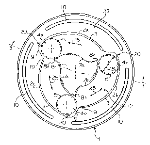
FIG. 1 is a plan view of the casing of the tree
stand according to the invention with the cover removed, the
clamping cylinders being positioned at the maximum distance
from the center of the casing;
FIG. 2 is a plan view of the casing with the
cover removed, the clamping cylinders being positioned at
the minimum distance from the center of the casing;
FIG. 3 is a cross-sectional view taken along
line III-III of Fig. 1, with the cover on;
FIG. 4 is an enlarged view of the detail X in
Fig. 3; and

FI~. 5 is a plan view of the undersid~ of the
cover shown in the direction of the arrow V in Fig~ 3.
DETAILED DESCRI_TION_(~F THE _I~RI F ~ t~ IMENT
Referring to Fig. 1, there is shown a casing with
an inner casing wall la having three spirally-curved
surfaces 2a, 2b and 2co One end 19 of the spi~ally-curved
surfaces is located closer to the center of the casing than
the other end 20. Between end 20 of the curved surface and
end 19 of the adjoining curved surface is formed a shoulder
9. Each of these surfaces 2a, 2b and 2c is fitted with gear
teeth 3 which interact with gear teeth 5 of a set of
clamping cylinders 4a, 4b and 4c.
Disposed in the center of casing 1 is a guide piece
6 fitted integrally on the casing bottom. Guide piece 6 is
provided with guide curves 7a, 7b and 7c, the curvature of
which matches curved surfaces 2a, 2b and 2c. The distance
between guide curves 7a, 7b and 7c and spirally-curved
surfaces 2a, 2b and 2c matches the lower diameter of
clamping cylinders 4a, 4b and 4c. Each guide curve 7a, 7b
and 7c has a stop 8a, 8b and 8c disposed therein. When the
clamping cylinders 4a, 4b and 4c are at stops 8a, 8b and 8c,
they are at a minimum distance from the center of the
casing, as shown in Fig. 2.
Likewise, the clamping cylinders are spaced the
maximum dist~nce from the center of the casing when they are
positioned at showlder 9, as shown in Fig. 1.

~ ~'7~ O;~
Guide slots 10 are formed in the top section 23 of
the casing. Guide pins 11 of cover 12 extend into the slots
10 as shown in Fig. 3. In addi-tion to yuide pins 11, the
cover is held in place by a clamping pin 21. Pin 21 has an
eccentric axis 13 which is connected with a bolt lever 14
fitted in a recess 22 of cover 12 formed in the upper
section of the casing, as shown in Fig. 4. After the tree
trunk is clamped, the cover is locked in place on casing 1
by pivoting the bolt lever 14 on its eccentric axis so that
1~ the bolt lever grips the surface of recess 22.
In Fig. 3, clamping cylinders 4a, 4b and 4c are
provided on their underside with slide shoes 15a, 15b and
15c for easing the sliding of the clamping cylinders on
casing bottom 17. In Figs. 3 and 5, it can be seen that the
operating components 16a, 16b and 16c, fitted in cover 12
and defined as semi-circular caps, grip clamping cylinders
4a, 4b and 4c so that when the cover is rotated on the top
section of the casing, the clamping cylinders move along
curved surfaces 2a, 2b and 2c in the direction of arrow 25
(Fig. 2). The clamping cylinders and particularly slide
shoes 15a, 15b and 15c move along the path formed by the
spirally-curved sur~aces 2a, 2b and 2c, and the curves 7a,
7b and 7c at the casing bottom 17. During this movement,
the distance of the clamping cylinders with respect to the
center of the casing is gradually reduced, thus clamping the
tree trunk.
Cover 12 also includes gripping recesses 24 fitted
in the cover surface to allow the cover to be easily rotated
on the casing.

~L~'7~3~
The center o~ cover L2 has an opening 25 for
inserting the tree trunk. After the tree trunk is inserted,
cover 12 which grips edch oE the three cylinders in
operating caps 16a, 16b and 16c, is rotated SO that the
cylinders are rotated from their position, as shown in Fig.
1, toward their position, as shown in Fig. 2. The cylinders
move between guide surfaces 7a, 7b and 7c and
spirally-curved surfaces 2a, 2h and 2c until the cylinders
contact and grip the surface of the tree trunk. The cover
is then locked into place by rotating bolt lever 14 mounted
on itS ecCentric pin 13 until the bolt lever grips surface
22 on cover 12 locking the cover from further rotation.
While only a single embodiment of the invention has
been shown and described, it will be obvious that many
changes and modifications may be made thereunto, without
departing from the spirit and scope of the invention.
3~

Representative Drawing
A single figure which represents the drawing illustrating the invention.
Administrative Status

2024-08-01:As part of the Next Generation Patents (NGP) transition, the Canadian Patents Database (CPD) now contains a more detailed Event History, which replicates the Event Log of our new back-office solution.

Please note that "Inactive:" events refers to events no longer in use in our new back-office solution.

For a clearer understanding of the status of the application/patent presented on this page, the site Disclaimer , as well as the definitions for Patent , Event History , Maintenance Fee  and Payment History  should be consulted.

Event History

Description Date
Inactive: Agents merged 2013-10-10
Inactive: IPC from MCD 2006-03-11
Inactive: Inventor deleted 1999-09-07
Inactive: Adhoc Request Documented 1994-06-26
Time Limit for Reversal Expired 1993-12-27
Letter Sent 1993-06-28
Grant by Issuance 1990-06-26

Abandonment History

There is no abandonment history.

Owners on Record

Note: Records showing the ownership history in alphabetical order.

Current Owners on Record
JAKOB GIES
Past Owners on Record
None
Past Owners that do not appear in the "Owners on Record" listing will appear in other documentation within the application.
Documents

To view selected files, please enter reCAPTCHA code :


To view images, click a link in the Document Description column. To download the documents, select one or more checkboxes in the first column and then click the "Download Selected in PDF format (Zip Archive)" or the "Download Selected as Single PDF" button.

List of published and non-published patent-specific documents on the CPD .

If you have any difficulty accessing content, you can call the Client Service Centre at 1-866-997-1936 or send them an e-mail at CIPO Client Service Centre.


Document
Description 
Date
(yyyy-mm-dd) 
Number of pages   Size of Image (KB) 
Cover Page 1993-09-22 1 13
Claims 1993-09-22 3 57
Abstract 1993-09-22 1 26
Drawings 1993-09-22 4 79
Descriptions 1993-09-22 6 162
Representative drawing 2001-08-16 1 15
Fees 1992-06-10 1 47