Note: Descriptions are shown in the official language in which they were submitted.
1~7~05~
CONTINUOUSLY VARIABLE TRANSMISSION
FOR MOTOR VEHICLES
The present invention is concerned with
continuously variable transmissions for motor vehicles.
Continuously variable cone pulley transmis-
sions for motor vehicles are known in the prior art. An
example is the transmission shown in German Patent
30 28 490, in which a part of the primary pulley
assembly is axially displaceable by the fluid
displacement piston of a hydraulic displacement servo.
The displacement piston of the displacement servo is
connected in an axially rigid manner to the driving
shaft of a continuously variable cone pulley
transmission. It is surrounded by a displacement
cylinder secured to the axially displaceable pulley
part.
To produce the desired clamping forces as a
function of the load, the primary shaft that supports
the primary pulley is provided with a sensor for the
torque transmitted by it. This torque sensor comprises
a driving collar that is axially rigid with respect to
the primary shaft but rotatable relative thereto. It is
connected by way of meshing teeth to a rotary ring, the
front side of which forms an annular piston received in
an annular cylinder in the rigid cone pulley so as to be
rotatably and axially displaceable. The rear side of
the rotary ring is formed with a V-shaped curved track.
A support ring adjacent the rotary ring likewise
comprises a V-shaped curved track. A support ring
adjacent the rotary ring likewise comprises a V-shaped
curved track. Rolling elements, such as steel balls,
are disposed between the tracks. The support ring is
rotationally and axially rigid with respect to the
driving shaft. Pressure fluid is supplied to the
torque
--`` l.Z7105~
sensor in the region of the cylinder-piston assembly by
means of a duct. It normally can flow away by way of
another duct. The other duct is arranged in such a way
that it is overlapped and controlled by one edge of the
front side of the rotary ring acting as an annular pis-
ton. That control occurs when the rotary ring is rotated
relative to the support ring upon a change in torque and
is axially displaced by the rolling elements between the
V-shaped curved tracks.
In this way, as the torque increases, the dis-
charge duct cross-section is progressively reduced
resulting in a control pressure that is proportional to
the torque. The control pressure acts upon the main
pressure control valve and produces a corresponding
increase in the pressure of the system.
Another prior art continuously variable trans-
mission unit for motor vehicles is shown in German
Offenlegungsschrift (Laid Open Specification) 32 41 789.
It has two hydraulically controllable friction disc
clutches for engaging a forward gear or a reverse gear by
means of a set of gear shifting planet wheels, the planet
wheel carrier of which can be coupled by the forward gear
clutch to a sun gear connected to the primary shaft of a
continuously variable belt-drive transmission. The
continuously variable belt-drive transmission has an
axially displaceable cone pulley part on the primary
shaft which is axially displaceable on the primary
shaft. The pulley part that is axially stationary is a
cone pulley connected to part of the piston of an
hydraulic displacement device. The piston of the dis-
placement device is connected in an axially rigid manner
to the primary shaft part of the continuously variable
belt-drive transmission. It comprises a stationary cone
pulley part and is surrounded by the displacement cylin-
der secured to the axially displaceable cone pulley part.
1~710~,~
In accordance with the present invention,there is provided in an infinitely variable belt drive
for delivering torque from a driving torque delivery
shaft to a driven torque delivery shaft; an adjustable
primary sheave assembly having an axially fixed sheave
part and an axially adjustable sheave part; an
adjustable secondary sheave assembly having an axially
fixed sheave part and an axially adjustable sheave part,
the secondary axially fixed sheave part being connected
to the driven shaft; a drive belt connecting the sheave
assemblies drivably; a ratio controlling servo for
adjusting the sheave parts of each sheave assembly, the
servo for one sheave assembly comprising a cylinder
movable with the adjustable sheave part of the one
sleeve assembly with an axially fixed piston assembly; a
torque sensor piston assembly in the torque sensor
cylinder comprising a first cam ring connected to the
axially fixed primary sheave assembly part and a second
cam ring adapted to be connected to one of the torque
delivery shafts; cam followers between the cam rings
adapted to separate the cam rings axially with a force
that is proportional to the torque applied to the belt
drive; the axially fixed piston assembly having a
pressure force reaction part that defines with the
servo assembly cylinder a working pressure chamber; the
second cam ring defining with the pressure force
reaction part a control pressure chamber; a control
pressure supply passage extending to the control
pressure chamber and a control pressure outlet flow
passage extending from the control pressure chamber;
and a control orifice in the piston assembly, the
second cam ring registering with the control orifice to
vary the flow area of the latter in accordance with the
magnitude of torque applied to the cam rings.
The invention, therefore, is an improvement in
a continuously variable transmission for a motor
A
1271059
vehicle comprising a torque sensor of the type
described above. The torque sensor is adapted to be
assembled in a restricted space. A minimum number of
changes is required to be made in the transmission to
accommodate the torque sensor. Simplified fluid
pressure sontrol passages are formed in the pulley and
shaft assembly.
In one embodiment, the axially stationary
displacement piston comprises a sleeve part, which is
secured to the guide hub of an axially displaceable
pulley part and is connected axially and rotationally
rigidly to an axially stationary cone pulley part. It
is axially displaceable relative to the guide hub by
reason of a splined connection. The sun wheel of a
planetary gear set is disposed axially rigidly but
rotatably relative to the axially stationary cone pulley
part. It forms a driving element for both the forward
gear clutch and the rotary ring which on its front side
forms an annular piston. That annular piston is
received in an annular cylinder formed in the axially
stationary displacement piston. The rear side of the
piston comprises a first V-shaped curved track which
cooperates by means of interposed rolling elements
(e.g., balls) with a support ring. The support ring
likewise comprises a V-shaped curved track disposed
axially and rotationally rigidly on the sleeve part that
is connected to the driving shaft.
A pump driving shaft extends through the
primary shaft. Inserted in the pump driving shaft is a
separation pipe which, with the pump driving shaft,
forms a pressure fluid duct. The duct supplies the
pressure space of the cylinder-piston assembly of the
torque sensor with pressure fluid by way of radial bores
and by way of spaces in the splined connection as well
as by way of the duct. It is possible for the torque
sensor and its pressure fluid supply to be formed merely
A
~2711)S~3
4a
by modifying the components that form the stationary
displacement piston and the sun gear with its driving
element. Inserting the separation pipe in the pump
driving shaft may be done without a need to change the
dimensions of the casing of an existing transmission
unit.
The invention is described in greater detail
with reference to the embodiment illustrated in the
lo drawings, in which:
Figure 1 shows a prior art continuously
variable transmission unit for front wheel drive motor
vehicles; and
Figure 2 shows an enlarged view of the region
indicated in the circle II in Figure 1 with a torque
sensor incorporated in accordance with the invention.
A continuously variable transmission unit for
front wheel drive motor vehicles, which is very compact
in terms of its axial and radial dimensions, is shown in
Figure l. An input shaft 1 is connected directly to the
driving engine by a damping disc arrangement 2.
The input shaft 1 is connected driveably to
the planet gear carrier 3 of a gearset, the sun gear 5
of which forms the input member for the continuously
variable belt-drive transmission 6, which is located
downstream and which essentially comprises a primary
shaft 7, a secondary shaft 8 and an infinitely variable
belt or chain 9.
71()~
The primary shaft 7 comprises a primary shaft
part 11, which has a stationary cone pulley part 10. It
is constructed as a hollow shaft on which iB mounted an
axially displaceable cone pulley part 12, which can be
displaced by means of an hydraulic displacement device
13. A stationary displacement piston 14 and a movable
displacement cylinder 15 comprise the device 13.
The secondary shaft 8 comprises a secondary
shaft part 17, which comprises an axially stationary cone
pulley part 16 formed on one side as a hollow shaft.
Cone pulley part 18 is mounted for axial displacement on
the hollow shaft. Part 18 is displaced by means of an
hydraulic displacement device comprising a stationary
piston 19 and a movable cylinder 20. The secondary shaft
8 forms the output shaft of the belt-drive transmission.
The sun gear 5, which forms the input member of
the belt-drive transmission 6, is connected rotationally
and rigidly on the primary shaft part 11 of the
belt-drive transmission. Planet carrier 3 has two sets
Of planet wheels 21 and 22, of which one set 21 engages
the sun wheel 5. Both sets engage one another and the
second set 22 engages the annular gear 23. On its outer
periphery the ring gear 23 carries clutch discs for a
reverse gear clutch 24, by means of which the ring gear
can be secured to the transmission casing. Thus, the
direction of rotation of the sun gear 5 can be reversed
with respect to the direction of rotation of the input
shaft 1.
One side of the planet gear carrier 3 iS con-
nected to a clutch drum 25, the outer periphery of whichengages discs of a forward gear clutch 26. The companion
discs of clutch 26 are arranged on a driving collar 27
which is directly connected rotationally and rigidly to
~71()S~3
the sun gear 5, the driving collar 27 and an annular
cylinder 28 for a corresponding annular piston 29 that
acts upon the forward gear clutch 26
The description of Figure 1 up to this point
corresponds to a transmission unit of the type known in
the prior art as described in German Offenlegungsschrift
32 41 789, wherein a torque sensor is unnecessary when
using a pusher element belt.
The torque sensor of the invention will be
described with reference to Figure 2. The region inside
the stationary displacement torque sensor is adapted to
be asembled in the region within the marked boundary II
of Figure 1.
In order to simplify the description the compo-
nents that correspond to those in Figure 1 have beengiven the same reference numerals but with a prime nota-
tion. Only components that are substantially differ~nt
have been given new reference numerals.
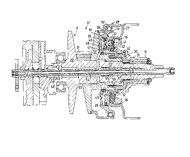
As may be seen from Figure 2, it is only neces-
sary to consider the region of the primary shaft 7'. Theprimary shaft 7' essentially comprises an axially sta-
tionary primary shaft part 11', which comprises a fixed
cone pulley part 10' that forms the driving shaft of the
belt-drive transmission 6'. An axially displaceable cone
pulley part 12', which is displaceable by way of an
hydraulic displacement device 13', comprises a stationary
displacement piston 14' and an axially displac~able
displacement cylinder 15'. Device 13 is mounted on the
axially fixed primary shaft part 11'.
In contrast to the design according to Figure 1,
the stationary displacement piston 14' is not rigidly
connected directly to the sun gear. It comprises a
multiple stepped sleeve part 30, which is rotationally
and rigidly connected at 31 to the driving shaft 11' by
way of a spline. On a step-like offset the sleeve part
1;~71()5~
-- 7
30 is connected rotationally and rigidly but axially
displaceable relative to the cone pulley part 12' by way
of a splined connection 32.
Sun gear 5' is mounted on the sleeve part 30 so
as to be axially rigid but rotatable with respect to the
latter. The sun gear 5' is again connected to a driving
collar 27', which not only forms a driving connection
with the forward gear clutch but also comprises teeth 35
on an annular shoulder.
Teeth 36 on an annular projection 37, which is
formed on the rear or a rotary ring 38, engage teeth 35
on the annular shoulder. On its front side the rotary
ring 38 forms an annular piston 39 and on its rear side
it comprises a V-shaped curved track 40 extending in the
peripheral direction. A support ring 41, which likewise
comprises a V-shaped curved track 42 extending in the
peripheral direction, is provided opposite the rear of
the rotary ring 38. The support ring 41 is connected
both axially and rotationally rigidly to the sleeve part
30 of the stationary displacement piston 14'. Rolling
elements 43 are interposed between the two curved tracks
40 and 42.
With its front side forming an annular piston 39
the rotary ring 38 is disposed in an annular cylinder 44
in the stationary displacement piston 14'. It forms a
fluid pressure chamber 45.
The fluid pressure chamber 45 is supplied with
fluid pressure through a first duct 46. Pressure fluid
can normally flow from chamber 44 by means of additional
duct 47. The additional duct 46 is arranged so that one
edge 48 of the annular piston 39 acts as a control land
for the additional duct 47. As soon as the rotary ring
38 rotates relative to the support ring 41 on account of
a change in torque, it is axially displaced by the rol-
ling elements rolling on the curved tracks 40 and 41.
1;~7~055~
: - 8 -
In the case of the transmission unit illustrated
in Figure 1, a hollow pump driving shaft 49 drives a
fluid pressure pump. It also supplies the pressure fluid
to the forward gear clutch 26. Shaft 49 extends through
the primary shaft 7 and in particular through the hollow
shaft part 11. The pressure fluid can pass out of the
hollow pump driving shaft 49 by way of radial bores 50,
which communicate with radial bores 41 in the primary
shaft part 11. Bores 51 are connected to a duct 52 which
is in communication with the pressure space formed by the
annular cylinder 28 and the annular piston 29 of the
forward gear clutch 26.
In the case of the transmission unit illustrated
in Figure 2, additional pressure fluid is required for
the torque sensor. The additional pressure fluid is
supplied by a separation pipe 53 disposed in the pump
driving shaft 49', thus forming a pressure fluid duct 54
connected by way of radial bores 55 in the pump driving
shaft 49' and radial bores 56 in the primary shaft part
11' to a first space inside the sleeve part 30. Fluid
flows from there through gaps in the splined connection
32 into a second space inside the sleeve part 30, from
where it reaches the pressure medium space 45 of the
torque sensor by way of the duct 46.
In this way the torque sensor can be fitted
inside the existing transmission space, thereby ensuring
its supply with pressure fluid.