Note: Descriptions are shown in the official language in which they were submitted.
7~L~ 3
A PROCESS AND A DEVICE FOR TREATING THREADS, SLIVERS
OR THE LIKE CONSISTING OF VARIOUS FILAMENTS AND
OPTIONALLY PROCESSED IN A TISSUE OR KNITWEAR, AND
THE LIKE.
The invention relates to a process and a device for
treating threads, slivers or the Like consisting of
various filaments and optionally processed in a
tissue or knitwear with a treating agent, a separation
S between the filaments being effected ;n order to have
the agent better penetrate into the structure of
filaments.
Similar processed and devices are generally known, in
particular for the production of composed materials
consisting of thermoplastic or thermosetting substances,
wherein ~ilaments function as reinforcing material.
For instance in Dutch patent application 70 01623 a
process is described, where;n the threads of sLivers
consisting of a great number of filaments are separated
before a synthetic res;n in powder form is applied
thereon, whereupon this resin ;s molten in result of
which a coherent product is obtained. The spreading
of the filaments in the slivers is for instance
effected according to the Dutch patent appl;cation by
giving to the f;laments an electrostatic charge with
the same sign. According to another embodiment the
,~ j
~;~7~ 3
21027--322
sliv~rs axe passed through a venturi, which in the same direction
is passed by a fluid at a high velocity. The spreacliny of the
filaments occurs -then under the influence of the relaxation of
the fluid on leaving the venturi.
The invention provides for a process for treating
material consisting of a p]urality of monofil~ ents, with a
treating agent, characterized in that the treati.ng agent is
suspended in at least one stream, which is then directed to the
material to ~e treated under a controllable pressure, so as to
separate the monofil~ ents and thereby treat the separated
a
monofi ~ments with the treating agent.
It has turned out that in this way a very efficient
spreading of~the filaments is effected, as a result of which
impregnating material suspended in the streams of fluid penetrates
well between the filaments and impregnate the same very homo-
geneously. This results in the inal product, for instance a
sheet of plastic material reinforced by filaments, being of a very
homogeneous composition.
The process according to the invention is applicable
no matter what the nature of the filaments or the nature of the
impregnating agent is.
For instance, powdery ceramic products and metal products
are considered as impregnating materials in addition to thermo-
plastic or thermosetting materials.
The process according to the invention is also feasible
for the application of layers of impregnating material of
various thicknesses on various sides of the material to be impreg-
nated. For instance a tissue or knitwear
-2-
il ;~'7~ t33
whirh is appliecl in~ernally or externally to a light-
weight core can be impregnated by application of the
invention~
As treating agent a grinding material can also be used,
which makes the material treated with it rough~ in
result of which it is made better suitable for the
adherence to it of a sizing and the like.
It is preferred to direct the gas streams wherein the
treating material is suspended with application of the
venturi principle to the material to be treated.
The treating material can be suspended in a gas stream
in various ways, for instance by atomizing it in the
gas stream as a meLt or Liquid. It is aLso possible to
dose a powdery treating material directly into a gas or
Liquid stream from a containeru It is aLso possible to
suspend the treating material in a fluidized bed in a
gas and to withdraw the gas streams to be directed to
the material to be treated from the fluidized bed by
suction power. Per se the application of a fluidized
bed for the impregnation of bundles of filaments is
known, for instance from Dutch patent specification
~51 928. ln this known method, however, the materiaL to
be impregnated is passed through the fluidized bed of
impregnating material.
If, however, in the process according to the invention
a fluidized bed is appl;ed, the actual ;mpregnation
occurs outs;de this bed.
The ;nvention also relates to a dev;ce for carry;ng out
~;~'7~3~
21027-322
-the invented process with a SpACe wherein via a perforated
bottom a ~as can be Eed and a supply pipe Eor powdery treating
agent, said device being characterized in -that the said space is
provided with one or more suc-tion pipings, which on the discharge
side debouch into means which are reciprocable movable trans-
versely to the path which the material to be treated covers during
operation of the device. If the gas is directed to the material
to be treated from various sides, care can be~taken that the gas
streams do not fully collide with each other.
It is also possible, applying the invention, to apply
various impregnating materials, either over each other, or to
various faces, in several spaces separated from each other, in
order to prevent an undesirable mixiny of the various
impregnating ma-terials.
The invention also provdes a device for treating
materials consisting of a plurality of monofi ~ments with a
treating agent, comprising:
means for guiding said material through a substantially open
space; and
means ~or supplying at least one stream containing a treating
agent to said materials in said open space so as to separate
said monofil~ ents and thereby expose each monofil~ment to said
treating agent.
The invention will be illustrated hereinunder by way of
example with the aid of the following description as well as the
enclosed figures.
~4~
3~33
21.027-322
Figure 1 .i5 a side view in cross-section of a
schematically drawn installation Eor carrying out the process.
Figure 2 is a top view of the dev.tce accordiny to the
invention.
Figure 3 is a side view of the very same device.
Figure 4 is a cross-section A.A. of the very same
device.
i -4a-
3~3
-5-
Fig. 5 is an enlarged representation of an essential
part of the device according to Figures 2, 3 and 4
Fig. 6 gives a number of variants a-e incl. of the
S application of the invention.
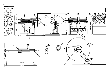
As represented in fig. 1 widths of continuous filament
beams 1 are formed by unwinding thern from the horizontal
coils 2 under automatically maintained controllable
tension. ~ia the guiding 3 the bundles come into the
preheating oven ~. The oven is heated with the
automatically controLlable heat source 5. Then the dried
and preheated filament beams are passed through a
thermally isolated receptacle 7, via the guiding 6, where
1S impregnation takes place !vide fig. 2-6 incl.). There-
upon the bundles are passed via the melting furnace 8,
wherein one or more heating bodies are applied controlled
by thermocoupLes. Same are automatically controlled by
the means 9 at a predetermined heating intensity. There-
upon the filament bundles are formed into bands andpassed through a cooling means 11 via cooled forming
rollers 10 and wound on the collecting coil 1~ via
delivering rollers 12 and the guiding 13. This coil ;s
driven by the electromotor 15. After the delivering
Z5 rollers 12 the band o~ ~ilaments can also further be
processed for instance by cutting it longitudinally
- andJor transversely.
The installation for carrying out the process can, if
desired, be carried out wholly or partly vertically.
In the device according to figures 2-5 incl. the bundles
of filaments in the thermally isolated impregnation
13~ 3
receptacle 7 are d;str;buted over the rollers 16,
wh;ch are positioned outside the feed1ng axes.
Optionally the axes of the roLlers 16 are mounted
pivotally about the shaft 17 pair-wise. This makes
S it possible that the bundles can be positioned in the
centerline when they are pulled into the device.
Spreading o-f the bundles over more than one layer of
rollers, in this case two, facilities a better
distribution of the filaments. After having passed the
rollers the filaments are impregnated. The powdery
impregnating material which is fed from the dosing
device 18, is flu;d;zed ;n the bed 20 ;n gas 21 fed
through the perforated bottom 19~
Preferably th;s gas ;s preheated. In the spaces 22
under the ;nfluence of pump;ng act;on~ gas streams
wherein the impregnating material is suspended are
sucked under controllable pressure from the fluidized
bed to the impregnating he~ds 23, from which it is
directed to the continuousLy moving bundles of -filaments~
In order to effect an optimal impregnation the
impregnating heads 23 are optionally adjustable with
respect to distance and/or an~le turning in regard of
the material to be ;mpregnated~
The various parts which are applied in the impregnat;ng
receptacle 7 can simply be d;splaced and/or replaced.
For ;nstance other types or roLlers, and/or other
impregnating heads can be used for the impregnation of
var;ous types of material~
The gas streams with therein the finely d;vided
1.~7~3~:~;3
impregnating material are preFerably directed -to the
filaments to be impregnated from two or more
impregnating heads. This results in a very homogeneous
distribution of the impregnating material over the
individual filaments. The impregnating method described
makes it possible to operate with a considerably lower
filament tension then required in a mechanical impreg-
nating system, in which -the impregnat;ng material is
pressed between the filaments by means of pressure
rollers. The lower filament tension results in the
substantial elimination of filament rupture which often
occurs in the mechanical impregnation of for instance
carbon f;laments~ Th;s comb;ned w;th the more intensive
impregnation also makes a greater impregnation rate
poss;ble.
In f;g. 5 ;t is indicated that the suction of the gas
wherein the impregnating material is suspended occurs
through the conduit 26 with application of the venturi
principle. V;a the condu;ts 25 gas is fed under a
controllable pressure. It is preferred to suck the gas
fed by a pump through the conduit 25 from the space 7
In result a circulation pump system of the gas is
obtained and heat losses are prevented.
If no use ;s made of a fluid;zed bed it is advantageous
to connect the dosing device 18 directly to the
impregnating heads or the;r supply mains.
When using ;mpregnatiny liquids it is preferred to
;nject the l;qu;d either d;rectly ;nto the impregnating
head(s) or to suck it d;rectly from the dos;ng device 18.
~,~7.~3C~3
--8--
In Fig~ 6 a plurality of schemes of emboclim~nts oF
more-sided and/or mobile impregnating heads are
represented, which are suitable for the continuous
impregnation of bundles of filaments optionally
processed ;n a tissue or knitwear. These bundles are
optionally applied to cores. These may have the
following shapes:
a. rectangular,
b. cyl;ndrical,
c. honeycomb-shaped.
For -the internal impregnation of hollow structures
fully closed along their circumference, which are
provided with filament materials, the process must be
discontinuous. Then impregnating heads can be applied
in the hollow spaces. Then the impregnating heads
and/or the material to be impregnated can be moved in
such a way that the desired impregnation is attained.
This is further illustrated with the aid o~ figures
6 e and d.
Fig. 6 d represents an aeroplane nose 27, which
internally and externally is provided with filament
material that has to be impregnated. For the internal
impregnation use is made of the impregnating head 78
and for the external impregnation of the impregnating
head 29. By rotating the nose and reciprocate the
impregnating heads 28 and 29 over guidings 30 and 31
the desired impregnation is obtained.
In fig. 6e 32 represents part of a dish antenna
internally and externally is provided with filament
material that has to be impregnated. This occurs by
~ J~
_9_
means of the impregnating heads 33 and 3l~, ~Jh;ch are
reciprocated radially via guidings ~5 and 36. ~f
desired, the motions described can be computer
controlled, which makes possible an optimal impregnation
S of more complex types of material~
If bundles of filaments processed into tissues or
knitwears are applied to cores, the impregnated
material is heated in an autoclave under a predetermined
desired pressure. Optionally, heat emitters can be
bu;Lt in in the autoclave.
According to the afore-described way impregnated
filament bands optionally woven into a certain shape
can be treated to aeroplane noses, radar domes and
other structures. It is also possible to apply a mel-ting
furnace consisting for instance of two mould halves
for heating.
In order to facilitate weaving, knitting and/or
twisting with impregnated filament bands can be
separated wholly or partly into narrower bands. These
narrow bands are then provided with an additional thin
impregnating layer with application of the process
according to the invention. This layer consisting of
a specially selected impregnating material sees to it
that the impregnating material already present between
the filament rema;ns in place dur;ng weav;ng and~or
knitting and besides prevents the adsorption of moisture.
In order to effect this the band may optionally be
subjected to for instance a temperature treatment on
the surface. Particularly in case of impregnating
materials of high rigidity the weaving and/or knitting
t~
- 1 0 -
with narrow bands, wh;ch have not been passe~ through
a melting furnace, is possibl.e without a considerablc
adaptation of the installations in question and loss of
veLocity. Then the tissue, knitwear and/or twisted
materiaL can be passed through a melting furnace in
order to be processed further optionaLly via cooLed
form rollers.
As treating agents may for instance be used:
Acetal resins
Acrylic resins
AcryLonitrile-butadiene-styrene resins
Aluminium
Alkyd resins
Aluminia
Aryl resins
Bismale;m;de res;ns
CobaLt
Copper
Ekonol
Epoxy res;ns
FLuorcarbon resins
Fluorcopolymers
Lead
Melamine res;ns
NickeL
Phenol resins
Polyacetalresins
PoLyacryLate
Polyamide (nyLon)
PoLybutadiene
PoLybutylenterephthalate
Polycarbonate
:LX7~3~3
.. .~
Aromatic polyesters
Thermoplast;c polyesters
Polyetheretherketones
Polyetherimides
Polyethersulfones
PoLyalkenes
PolyethyleneterephthaLates
Polyimides
Polyoxymethylen resins
Modified polyphenylene ox;des
Polyphenylene sulfides
PoLyphenylene sulfides
Polyphenylenoxides
Polyphenylsulfones
Polystyrene
PoLysulfone
Polytetrafluorethylene
Polyurethane
Polyvinylchloride
Polyvinyl;dene fluoride
Modif;ed polypropylene oxide
S;lica
Silicon carbide
Silicon nitride
Silicone
Styrene acrylonitriLe copolymers
Styrenic copolymers
Titanium
Tungsten
Urea
Vinyl ester
Rubbers
7'~ )3
-12-
and additives like:
Anti static agents
Blowing agents
Colorants
Concrete
Coupling agents
Fillers
Flame retardants
Foam materials
10' Heat stabilizers
Hollow fillers
Lubricants
Minerals
Plasticizers
Processing aids
Silicones
Stabilizers
Superalloys
Ultraviolet absorbers
Water soluble plastics
Whiskers.
The material to be treated may for instance consist of:
Aluminium
Aluminium oxides
Aramide
Asbestos
Boron
Carbon
Cobalt
Copper
Glass
High silica and quarz
L;thium aluminium silicate
-1 3-
Magnesiuln
Nickel
Polyalkene
Silica
Silicon
Silicon carbide
Sil;con nitr1de
Steel
Titani um
Tungsten
Zinc
Zirconia
Zirconium~