Note: Descriptions are shown in the official language in which they were submitted.
~%7~L457
~AC~C(:;RQ~D OF T _INVENTION
This invention relates to pump dispensers, particularly
for viscous products such as toothpaste and the like, and more
especially relates to a positive discharge valve for the
dispenser.
U.S. Patent No. 4,629,097 discloses a viscous product
pump dispenser having a discharge SpOIlt in communication with a
hollow piston stem which therewith defines an unvalved
discharge passage.
When filling the dispenser product is loaded to fill the
dischar~e passage as much as possible, Thus the loaded
dispenser may be shipped fully primed. Otherwise, if the
discharge passage is partially filled, it becomes necessary to
assist the priming action by pressing inwardly on the lower
piston follower normally provided for such dispensers.
However, a filled discharge passage, even partially,
presents a number of problems. During storage, the product in
the spout can dry out or lose its flavor. Otherwise, product
could unintentionally ooze from the spout if the dispenser is
dropped or exposed to adverse ambient conditions. Still
further, voids or bubbles in the product could affect pump
priming during use.
~ nother pump dispenser for viscous products is disclosed
in U.S. Patent No. ~,511,068 having a one-way flap valve
25 located in the discharge passage such that downward movement of
the piston causes the exerted pressure to be transmitted to the
viscous product contained within the container to thereby open
~; the valve. Similar problems are encountered as in the
aforedescribed valveless discharge dispenser in that upon
--2--
. . ~ , ' '' ~
gL27~
~illing the dispenser under pressure the product could easily
open the flap valve and enter the spout where it is e~posed to
air and could become dried or caked or could ooze out of the
spout or be inadvertently extruded if the dispenser is dropped
in any attitude. Messy conditions are therefore encountered
with the use of these dispensers.
.
SUMMARY OF THE INVENTION
It is therefore an object of the present invention to
provide a positive discharge valve ~or viscous product
10' dispensers of simple construction, easy to operate and
economical to produce while avoiding the problems of known
dispensers of this general type.
The positive discharge valve o the present dispenser is
connected to the movable spout for movement therewith upon
actuation, the valve bearing against the piston in a valve
closing position under the bias of a return spring associated
with the spout. The valve therefore acts as a link to return
the pump piston to its initial position under the action of the
spring. And, the spout and piston are interengaged for
relative movement. of the valve upon initial actuation of the
spout Eor thereby opening the discharge valve. Upon continued
actuation of the spout with the discharge valve open, the
piston is inwardl~ stroked forcing product into the discharge
passage to effect positive priming. When primed, product is
discharged through the spout upon piston actuation.
The aforedescribed problems experienced during use of
the known dispensers are essentially avoided with the present
;7 `~
dispenser. When filled, product is not loaded above the closed
discharge valve and cannot force the valve open. Thus product
does not enter the spout, and will not dry or cake or
inadvertently extrude from the spout if the dispenser is
dropped. Thus, medium or lighter viscosity products can be
stored and dispensed. And, because of the positive valving and
upper pump piston action, the dispenser can be shipped
unprimed, i.e., with no product in the spout. Thus, it is not
necessary to assist the priming action by pressing inwardly on
the lower piston assembly since the poppet valve action
facilitates self priming and/or repriming when encountering a
bubble or void in the product.
Other objects, advantages and novel features will become
more aparent from the following detailed description of the
invention when taken in conjunction with the accompanying
drawings.
BRIEF DESCRIPTION OF THE DRAwI~Gs
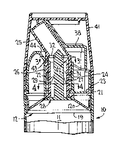
Figure 1 is a longitudinal, vertical cross-sectional
view of a dispenser structured in accordance with the invention
showing an overcap in place and the positive discharge valve
closed;
Figure lA is a sectional view similar to Fig. 1 of a
portion of the dispenser showing the discharge valve open upon
initial actuation of the spout;
Figure 2 is a view similar to Figure 1 showing the lower
follower piston assembly, the overcap removed and the positive
discharge valve opened upon actuation of the spout and
remaining open during pumping movement; and
:.
--4--
.
457
Figures 3 and 4 are cross-sec~ional views taken
substantially along the lines ~-3 and ~-4, respectively, of
Figure 1.
: DETAILED DESCRIPTION OF THE INVENTION
S The pump dispenser of Figures 1 and 2 is similarly
constructed as in U.S. 4,629,097 in that it has a long,
tubular, normally upright body 10 defining an internal pumping
chamber 11 between an upper pump piston 12 and a lower follower
piston 13. The lower end oE body 10 may have an outwardly
flaring skirt 14 to facilitate standing the dispenser in an
upright condit;on on a support surface. Follower piston 13 is
of known construction designed to upwardly move through chamber
11 as the contents thereof become progressively depleted during
pumping. The follower piston has an outer peripheral skirt 15
in sealing engagement with the inner surface of body 10. This
piston is adapted for upward movement by the provision of a
one-way, anti-retrograde means 16 which may be in the form of a
downwardly and outwardly flaring thin metal skirt 17 or the
lilce which makes biting engagement with the internal surface of
body 10. The angle oE attack o metal skirt 17 with the
internal body surface is that skirt 17 will 1e~ downwardly a
sufficient e~tent to permit upward movement o the follower
piston ~et dig into the body surface with sufficient force when
downward movement is applied to the top o piston 13 so as to
prevent downward movement thereof within body 10. ~ cover 18
may be friction fitted to the lower end of the piston follower
overlying means 16 as shown.
-5-
;
:' ' '
.. . .
( ~ ~
Piston 12 has a piston head l~a with a peripheral seal
skirt 19, 21 which wipe alon~ the inner surface of body 10
during piston reciprocation. A hollow piston stem 72 extends
through a central opening in a transverse upper wall 23 of the
S body, and is surrounded by a spaced cylinder 24 of the body. A
-tubular discharge spout 25 has a depending sleeve 26 located
for telescoping sliding movement between stem 22 and cylinder
24. A coil spring 27 is likewise located in the space between
stem 22 and cylinder 24 and acts between wall 23 and the lower
end of sleeve 26 for spring biasing the spout outwardly.
A positive discharge valve 28, which may be in the form
of a poppet valve having a central valve stem 29, extends
through the piston stem and is of a smaller diameter defining
an annular passage 31. The valve stem is connected to the
spout for movement together therewith in any normal manner, as
for example b~ a spider 32 (Fig. 3~ presenting through openings
33 allowing passage of the viscous product. And, the valve
stem has a plurality of guide ins 34 ~Fig. ~) for maintaining
the valve stem centered within the piston stem upon relative
movement thereof as will be described in more detail
hereinafter. A valve flange 35 at the lower end of the valve
stem has an upper edge 36 which matches the shape of the inner
surface of piston head 12a. This inner surface is conical as
shown in the drawings, although other shapes are suitable
without departing from the invention. The valve 1ange is
spaced a suitable distance from spider 32 as to tightly bear
against the undersurface oE the piston head, as shown in Figure
1, under the resiliency of spring 27 which upwardly biases both
the spout and valve. And, the piston head 12a has a circular
..
-
ring 37 on its outer surface which bears against the underside
of wall 23 in the at rest position of Figure 1 under the
resilenc~ o the spring, (to positively support the valve seat
at its prescribed location). The combined stroke including
valve action and pumping displacement are thus positively
limited by ring 37 which therefore isolates thP load on the
piston to prevent any piston distortion.
- An actuator 38 may be pivotably mounted on the spout ~or
movement into its Figure 2 position in which its cover 39
uncovers the end of the spout upon manual depression of the
actuator with the overcap 41 removed. ~therwise, the actuator
may be of a different cons~ruction with or without a cover 39,
or may be eliminated altogether such that the spout is directly
actuated as in U.S. ~,511,068, without departing from the
invention.
There is a lost motion between the spout and the pump
piston at the initial actuation o~ the spout. This lost motion
is effected by spaced apart stops on these two members
permitting limited sliding movement relative to the pump piston
for opening the discharge valve before the pumping movement of
the piston. Such spaced stops may comprise a shoulder 42 and
an upper free edge ~3 of the piston stem spaced a predetermined
distance therefrom in the at rest position o Fig. 1. The
shoulder may be in the form of a continuous integral ring or a
plurality o~ detents in the spout. With the aEoredescribed
structural arrangement according to the invention, the pump
piston is unattached to any member. Its outer ring 37 bears
tightly against the underside of wall 23 under the bias of
spring 27 which urges the spout outwardly and thereby
S~7 ~3
resiliently urges the connected discharge valve 28 outwardly
such that valve flange 35 is drawn tightly against the
undersurface of piston head 12a, as shown in Figure 1. The
discharge valve thus acts as a link to retract the pump piston
during pumping movement.
In operation, with pump chamber 11 filled with viscous
product loaded to the underside of the piston head and the
valve flange, overcap 41 is removed, and upon initial
depression of actuator 38, there is lost motion between the
spout and the piston stem as telescoping sleeve 26 moves
relative to piston stem 22 a predetermined distance permitted
by the spaciny between stops 42 and 43. Since the discharge
valve is connected to the spout and moves together therewith,
the relative movement causes the discharge valve to open as
valve flan~e 35 moves inwardly relative to the piston head
which remains bearing against wall 23, as clearly shown in
Figure lA. Guide fins 34 maintain the concentricity of valve
stem 29 relative to the piston stem so as to assure an even
opening and closing of discharge passage 31 around the
periphery oE the valve flange. As stops 42 and 43 interengage,
continued depression of the spout effects pumping movement by
inwardly stroking the pump piston as shown in Figure 2. Inward
travel of the piston is limited by Stop means suCh as the lever
of actuator 38 bottoming against transverse wall 23 or cylinder
24. A stop shoulder 44 oE the pump body may also serve ko
limit inward travel oE the spout which bears thereagainst at
the end of the piston stroke, as illustrated in Figure 2. Upon
each release of the actuator or spout (if no actuator is
; employed), the discharge valve first closes in response to the
-,
-8-
-
' " '. " :
~` ~
~L27~5i7
action of the spring which shifts the spou~ and its connected
valve outwardly until valve flange 35 seats against the piston
head for positive prevention of any backflow from the spout
while returning the piston to its initial Figure 1 position.
As in known viscous product dispensers having a follower piston
such as 13, the follower piston assembly follows the product
upwardly during dispensing by the vacuum produced within the
body as assisted by atmospheric pressure actlng against the
outer side o the ollower piston.
The piston is actuated as aforedescribed for positively
priming the dispenser as discharge passage 31 fills with
product. When fully primed, product is dispensed during
pumping through the spout which is opened upon uncovering cover
39 if actuator 38 is employed.
Although the present dispenser has been described with
reference to actuator 38, the actuator shown may be substituted
by some other suitable actuator or may be completely eliminated
without departing from the invention. Inskead, the spout may
be actuated directly by the user and may be provided with a
` 20 finger rest (not shown) for this purpose.
Obviously, many other modifications and variations of
the present invention are made possible in the light of the
above teachings. It is thereore to be understood that within
the scope of the apended claims the invention may be practiced
otherwise than as specifically described.