Note: Descriptions are shown in the official language in which they were submitted.
-- NHL-KF.J-23
FIXED BED REAC'~OR COLUMN FOR ANAEROBIC DECOMPOSITION PROCESSES
BACKGROUND OF THE INVENTION
1. Field of the Invention: `
The invention relates to a reactor column for the implemen-
tation of anaerobic decomposition processes with a fixed bed,
through which the reaction fluid travels upward.
2. Descrip~lon of the Prior Art:
The execution of anaerobic decomposition processes on
carrier-fixed microorganisms is increasing in importance. The
anaerobic purification of waste water appears particularly bene-
ficial. In this process, in contrast to the activated sludge
process, relatively sm.all amounts of residual sludge are formed
and the energy balance of the entire process is more favorable,
since on the one hand, there is no need to introduce oxygen, and
on the other hand, the biogas formed can be used as an energy
source
A prerequisite for a commercial application of the proces~
is high efficiency per unit of.volume and per unit of time, that
is, for a given reactor volume, the maximum quantity of waste
water substrate must be treated in the shortest possibLe time.
Recently, therefore, processes have been de~eloped or the
immobilization of active biomasses which make it possible to deal
with quantities of waste water like those treated commercially in
an acceptable length of time using reactors of an acceptable
size. But a problem which occurs with the use of beds of small-
particle carrier materials, for example, with a size of 5 to 15
mm, which exhibit a surface large enough for cell fixation, i9
that excessive s1.udge is formed after a period of extended opera-
tion, which leads to clogging and llmitations of diffusion, and
~ 8~ ~- ~ 70577-44
to the formation of graft flows. In addition, the amount of
biogas contained in the reaction mixture increases as the reac-
tion proceeds, which has an adverse effect on the treatment
system (solid/liquid/gas).
For these reasons, reactor columns with small-particle
carriers, with fixed beds more than approximately 2 meters in
height, are no longer considered optimal.
A reduction of the specific activity of the column, in
order to prevent the increasing clogging of the fixed bed, or a
corresponding limitation of the height of the reactor, does not
appear very economical, since on the one hand, the overall
reactors would have to be larger, and on the other hand, the
ground space required for a "flat" design with the appropriate
column cross section, or a number of parallel columns, would not
be economical.
OBJECTS OF THE INVENTION
It is therefore an object of the invention to provide
a reactor column design adapted to the requirements of actual
practical applications, by means of which high specific activi-
ties of the biocatalyst can be allowed and successful operation
is possible over long periods.
It is a further object of the invention to provide a
high-rise design for a reactor column which can be constructed
requiring only a limited amount of ground space.
SUMMARY OF THE INVENTION
According to a broad aspect of the invention, there is
provided an improved reactor column for the performance of anaero-
bic decomposition processes by means of a fixed bed layer through
which reaction liquid flows upwardly, comprising: a jacket means
defining the reactor column and having therein at least two
,
~2~;~
70577-44
individual fixed bed reactor segments disposed one above the
other in a stacked relationship, each of said segments including
floor means having means for permitting flow therethrough; a
fixed bed layer being disposed on each of said floor means; a
void in each said segment being defined above each fixed bed
layer; gas discharge means including means generally in the
shape of an inverted funnel for collecting gas disposed in the
void above each fixed bed layer, said gas collecting means being
in communication with at least one ascending gas discharge pipe;
and fluid inlet means disposed underneath each said means for
permitting flow therethrough of each of at least two individual
fixed bed reactor segments.
According to a specific embodiment of the invention,
the reactor column for the performance of anaerobic decomposition
processes by means of a fixed bed layer through which reactional
liquid flow upwardly comprises a jacket means which defines the
reactor column. Within the reactor means are at least two
individual fixed bed reactor segments or individual reaction
zones which are disposed one above the other in a stacked
relationship. Each of the individual fixed bed reactor segments
includes a screen-like floor means upon which is disposed a
fixed bed layer of a predetermined height. There is also defined,
above each fixed bed layer, a void in each of the individual
segments. A gas discharge means includes means generally in the
shape of an inverted funnel disposed in the void above each fixed
bed layer. The inverted funnel means is in communication with
at least one ascending gas discharge pipe which is mounted exter-
nal to the jacket means. This communication can be established
by means of a transition pipe which is disposed upwardly and
outwardly toward the jacket wall with respect to the inverted
i i.
~ ~2 70577-44
funnel means. Fluid inlet means are disposed underneath each
of the screen-like floor means of each of the individual seg-
ments. Additionally, a star-shaped feed distributor means for
the introduction of the reaction liquid into the reaction
column is disposed on the column floor just below the screen-
like floor which defines the bottom-most segment of the
reactor column. A liquid extraction means is disposed at the
upper end of the fixed bed reactor in the void defined above
the upper-most fixed bed reactor segment. The liquid extraction
means is in the form of a closed tube with upper feed holes.
- 3a -
- NHL~KFJ-23
~2~2
BRI~, D~S~IYTION OF_rUE DRAWINGS
The above, as well as other features and ad~antages of the
present invention, can be appreciated through consideration of
the detailed description of the invention in con~unction with the
several drawings in which:
Figure 1 is a schematic elevational view of the impro~ed
reactor column incorporating the features of this ~nvention;
Figure 2 is a cross-sectional detailed view of a section of
the reactor column of this invention illustratlng the inverted
funnel gas discharge, the screen-like floor and ~he fixed reactor
bed; and
Figure 3 is a cross-sectional detailed view of the upper-
most portion of the reactor column of this inventlon illustrating
the liquid extraction means disposed therein.
DESCRI~TION OF THE PREFERRED EMBODIMENT
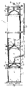
The column reactor 1 shown with a thermostat jacket 2 is
divided into four segments 3, each of which includes a fixed bed
layer 4 on a screen floor 5, and a space S which leads into the
side tubes 7.
In the space 6, above an annular guide element 8, there is a
gas discharge funnel 9, which forms an "annular gap" 10 together
with the annular guide element 8. This annular gap 10 can be
adjusted by adjusting the height of the funnel 9 by means of one
or more adjustment screws 11. From a funnel tube ~', a connec-
ting tube 12 leads upward and outward through the fixed bed layer
4 to an ascending pipe 13, which reaches at least the height of
the liquid discharge via the annular extraction tube 15 from ~he
column reactor and leads to a gas collecting chamber (not shown).
~X~715~72 NHL-KFJ-23
All o~ the segments can empty into this ascending pipe 13,
or there can also be separate ascending pipes which lead to the
gas collection chamber.
The reac~ion liquid travels through a star-shaped distributor
14 on the screen floor 5 of the column reactor, is distributed
over the cross-section into the fixed bed, and converted liquid
is extra via an annular extraction tube 15 with outlet tubes from
the reactor column. This annular extraction tube 15, in its
upward-pointing surface, has ho:Les 16, by means of which the
liquid is ex~racted from the reactor. A triangular cross-section
of the extraction tube, with the point downward, is appropriate.
The gas discharg~ funnel 9 of the final column segment is no
longer in the screen floor, but is installed in the column cover
17, and its funnel tube 18 leads directly to the gas collection
chamber.
The column packing can be formed by carrier particles of the
prior art wi~h microorganisms immobili~ed on them, or by granular
materials, etc., charged with biomasses. The individual segments
can also exhibit additional pipes for probes 9 sampling, control
liquids, etc.
To remove excess sludge, flushing liquids can be forced
through the column segments during a pause in operations, for
example, via the lower fluid distributor 14 and the side tubes or
lateral pipes 7. In this case, the fulmel 9 is appropriately
placed in its highest position.
With such a reactor column divided into fixed bed segments
located above one another with spaces in between, an effective
and :Long-term operation can be achieved, since excess sludge is
discharged, on the one hand, via constant floatation phenomena
through the gas lines (and is separated in the sludge separator
12 7 ~5~72 NHL-KFJ-23
of the g1S collec~ion chamber), and on the other hand, can be
expelled in intermediate phases by a flushing medium, which is
admitted in the reverse direction via the appropriate inlets
beneath the screens.
The spaces between the segments are a function of the dis-
tance between the upper end of the ixed bed layer of a segment
and the permeable floor or screen of the subsequent section. In
this space are the inverted-funnel gas discharge lines which,
mounted in the screen, are conducted through the packing of the
subsequent segment outward to ascending pipes.
Annular guide elements interact with the inverted-funnel gas
dlscharge lines and project from the circumference into the
colu~m, narrowing the cross section, the opening cross section of
which is smaller than that of the funnel base, so that the gas
bubbles contained in the ascending gas/liquid mixture are intro-
duced into the funnel, while the liquid flows through the "annular
gap" between the conductor and the funnel outward and upward to
the next segment.
The "annular gap" should thereby have a cross section so
that no significant pressure loss occurs at this point. To make
possible an optimal adjustment of the free cross section of this
"annular gap" to the prevailing conditions, the gas discharge
funnel is mounted so that is vertical position inside the space
can be adjusted
The base cross-section of the gas discharge funnel, which
interacts with the annular guide element, can essentially be as
large as desired, but the funnel cross~section is advantageously
one which largely covers the column cross section and still
leaves sufficient space for the liquid flow.
-~ NHL-KFJ-23
The angle of inclination of the funnel cone from the horl-
zontal is optimized within the space, bearing in mind that an
exce~sively flat funnel can result in loss of bubbles, while a
funnel with excessively steep sides is inappropriat~ because of
the height limitations of the space. Inclinations between 15
and 60 are appropriate, especially an angle of approximately
35o.
To facilitate the gas disc'harge from the funnel into the
ascending pipe, an ascending connecting tube is selected, one
which specifically has an angle of 15 to 30~ to the horizontal.
The gas discharge funnel can lead to a separate ascending
pipe or lnto a common ascending pipe. The ascending pipes extend
at least to above the upper fluid discharge of the reactor and
empty into a gas collecting chamber. The cross section of the
gas discharges from the lower segments of the column can, if
necessary, be made larger to accommodate a more intensive gas
generation in the lower portion of the column than the discharge
- lines from the higher portions.
The individual segments of the co].umn reactor can be identi-
cal to one another, to facilitate their manufacture However, itmay also be appropriate if the height of the segments lncreases
with the height of the reactor column, so that consideratlon can
be given to a decrease in the concentration in the substrate as
the reaction proceeds (column height).
In a similar manner, the grain size of the carrle~ or the
diameter of the carrier particles can be graduated from bottom to
top, whereby the larger particles, for example, 30 to 50 mm in
diameter, are in the lower region and the finer particles, for
example, down to 15 to 9 mm in diameter, are in the upper region.
- NHL-KFJ-23
~2~
The la~eral i.nlet tubes below the screens, by means of which
a flushing out of the excess sludge is a~h~eved, offer additional
possibilit-J.es of process control by means of the addition of
substrate distributed vertically, partial recycling, or even the
addition of reagent.
The a(Idition of the reaction liquid is done as usual at the
bottom of the reactor column, specifically by means of a star-
shaped liquid distributor, and at the top of the column the reac-
tion liquid is extracted by means of an annular extraction tube,
which exhibits holes 4 to S mm :Ln diameter pointing upward, by
means o~ which the liquid to be extracted enters into the annular
tube.
The bed height of the individual fixed bed segments is
appropriately 50 to 200 centimeters, specifically 100 to 160
centimeters, in the case of fixed biocatalys~s with an activity
of 5 - 16 kg- COD/kg x d (x = biomass concentration as dry mass~,
anc~ is also a function of the COD (COD = chemical oxygen demand)
of the feecl.
The construction of the reactor column described above is
suitable for anaerobic processes in the fixed bed with and with
out recycling of the liquid used.
What has been described is an improved fixed bed reactor
column, by means of which high specific activities of the bio-
catalyst can be allowed and successful operations are possible
over long periods.
The invention as described hereinabove in the context of the
preferred embodiments ls not to be taken as limited to all of the
provided deta:ils thereof, since modifications and variations
thereof maY be made without department from the spirit and scope
of the invention.