Note: Descriptions are shown in the official language in which they were submitted.
SHEATH CUTTI~G TOOL
FIELD OF THE I~VENTIO~
This invention relates to a novel cutting
tool. More particularly, this invention relates to a
novel cutting tool which is specifically adapted to
cu-tting the protective sheath of conducting cable
without cutting or damaging the underlying conducting
elements of the cable.
~CKGROUND OF THE INVENTION
:L5
In the te:Lecommunlcatlons in~ustry/ ancl
particularly the telephone industry, it i9 constantly
necessary in order to enable hook-ups to be made, to
access the conductors of protectively sheathed conductor
cables, most commonly, polylethylene sheathed conductor
cables. To accomplish this task, a tough protective
polyethylene sheath and an underlying aluminum sheath
must be cut and removed from a specific length of the
! cable without damaging the conductor elements which lie
directly underneath the protective layers. This is a
delicate task because, typically, the conductor elements
are separated from the polyethylene and aluminum
sheathing by only a relati~ely thin layer of paper or
mylar, which provides negligible protection. As a
result, there is a strong need for a cutter tha-t is
capable of cutting the polyethylene and aluminum
sheathing both longitudinally and circumferentially to a
precise depth without damaging the underlying conductor
elements.
,
~ Z ~ ~2 ~
Because of the curved nature of the sheathing
being cut, there ls a tendency for any cutting blade to
veer off the intended line of the cut, unless the cut-
ting blade is supported laterally (across the line of
cut).
secause considerable force is required to draw
a blade through the tough protective sheathing layers,
any occasion when the blade slips out of the sheathing
being cut is necessarily followed by a somewhat violent
"follow-through". ThiS action endangers anything that
lies in the path of the tool, including the operator's
"non-cutting" hand. The tool of this invention over-
comes this hazard by way of a blade which retracts
immediately and EorceEully upon di~engagement with the
material be~ng cut by the tool. Cutting ~heathing Erom
conductor cab.~e traditionally has been performed by the
use of a fixed blade. But the lack of precision and the
safety hazard presented by the use of a fixed blade has
made such use prohibitive. Frequent injuries have
resulted when the blade inadvertently slips out of the
sheath during the cutting process. Cuts to the
operator's non-knife holding hand which is usually used
to hold the cable in place during the longitudinal cut,
is a common occurence.
Rrecision in depth of cut has also been a
problem due to the lack of any means for precisely
determining the depth of cut when a fixed blade is used.
The result is that conductor damage often occurs.
There is nothing in the prior art, to the
inventors knowledge, that encompasses both a tool which
is capable of precisely determining the depth of cut and
has a safe, retracting blade in a form which is compact
and streamlined and which is useful in confined
- 2 -
1~7162~
quarters, where conductor cable sheathing is often being
cut.
The inventor is aware of the following patents
which disclose various forms of cutting tools:
U.S. Patent No. Inventor ~ssue Date
1,739,972 Klinger December, 1929
2,187,215 Spinello January, 1940
2,616,172 Parker November, 1952
3,906,561 Bawa September, 1975
3,906,627 Manning September, 1975
4,139,939 Crooks February, 1979
~,~33,~ Antl~del et al. February, l~8
4,507,867 Haas, ~r. April, 19~5
Bawa does not disclose any means of precisely
determining the depth of cut. Also, since his tool is
attached to pliers as specified, it is too cumbersome
for cutting sheathing from conductor cable. The blade
in ~awa's device can easily be held in an extended
position while cutting. Bawa does not disclose any
means of lateral support to maintain the line of cut.
Manning also does not disclose any lateral
support means to maintain line of cut. In Manning's
design the angle of blade cutting edge to the hand angle
of the tool is inappropriate for the job of cutting
sheathing on a conductor cable. Manning's blade can be
held extended manually while cutting.
Haas, Jr. discloses a large cumbersome cable
sheath cutter knife which is always exposed. His cutter
knife design has no lateral support to maintain the line
; of cut and no depth control facility. Consequently the
-- 3 --
~7~
blade can easily cut or damage the underlying conducting
elements of the transmission cable.
Antisdel discloses a design of cutting knife.
Antisdel has a projection which must pass bet~een the
conductors and the sheath thus increasing the force
necessary to accomplish the task at hand. The thickness
of the head must pass through the cut directly after the
blade, which inhibits cutting action.
Crooks discloses a cutting knife design but
the angle of the cutting blade edge to the hand angle is
awkward and inefficient. His design has no depth of cut
regulation capability. He also does not provide any
lateral support to maintain line of cut on a cylindrical
object such as a conductor cable.
Parker discloses a slitter for cable
coverings. The slitter has a depth control facility
but the blade is not retractable. The cutter is large
and cumbersome.
Spinello discloses an electrical insulation
cutter which has a non-retractable blade that pivots
about a pin which is positioned midway along the handle
of the cutter. His cutter is inappropriate for cutting
the sheath of large diameter conductor cables.
Lastly, Klinger discloses a cable splitter
which has an exterior blade. The blade is not
retractable. Moreover, there is no depth control
facility in the Klinger cable splitter design.
1.,'~'7~
SUMMARY OF THE INVENTIO~
A cutting tool useful for cutting sheathing on a cable
comprising: ~a) hand-grip holder for holding therein a cutting
blade in a retracted position or in an extended position, (b) a
cutting blade and blade moving means for p~lshing manually the
blade from a retracted position to an extended position and
alternatively from an extended position to a retracted position;
(c) spring means for urging the cutting blade into a retracted
position when the cutting blade is in an extended position; and
(d) stop means for controlling the distanc~e that the cutting
blade extends from the holder when in an extended position.
In the cutting tool, the blade may be pushed from a
retracted to an extended position or from an extended position
to a retracted position by means oE a control means which is
located on the exterior oE the holdiny means. In the cutting
tool, the control means ma~ be loc~ted on the top o~ the holding
means. In the cutt:Lng tool, the yieldlng biasing means may be
a coil spring located in the interior of the holding means.
The invention also includes a cutting tool wherein the
holding means may have finger and thumb grips constructed on one
side of the holding means and a palm grip located on the side of
the holding means opposite the finger and thumb grips. The
control means may be located on the same side of the tool as the
palm grip. In the c~ltting tool, the distance that the blade
extends from the holding means may be controlled by an abutment
formed in the holding means. The abutment may be formed in the
end of the holding means from which the blade protru~es when in
an extended position.
A cutting tool wherein the cutting blade may have
formed in the end of the cutting blade a point which protrudes
from the end of the holding means when
~L~7~
the cutting klade is in an extended position. In the cutting
tool, the holding means may be opened in order to replace the
cutting blade. The surface of the holder may be roughened to
enhance grippability.
DRAWINGS
In drawings which illustrata a specific embodiment of
the cutting tool, but which should not be construed in limiting
the scope of the invention in any way:
Figure 1 illustrates a side elevation view of the
cutting tool slitting the sheath of a sheathed cable conductor;
- Figure 2 illustrates a top view of the cutting tool;
Fiyure 3 illustrates a side view of the cutting tool;
Figure ~ illustrates a bottom view of the body of the
cutting tool;
Figure 5 illustrates a bottom view of the underside of
the top plate of the cutting tool;
Figure 6 illustrates a side view of the top plate of
the cutting tool;
Figure 7 illustrates a bottom view of the bottom plate
of the cutting tool;
Figure 8 illustrates a side view of the bottom plate
of the cutting tool;
L6;2 ~
Figure 9 illustrates a top view of the bottom plate of
the cutting tool;
Figure lO illustrates a cut-away side view of the
cutting tool with blade retracted;
Figure 11 illustrates a cut-away side view of the
cutting tool with the blade extended;
Figure 12 illustrates a detailed side view of the blade
mounting and extending mechanism.
Figure 13 illustrates a detailed side view of the
cutting tool with an adjustable blade stop in the end.
DETAILED DESCRIP~'ION OF A SPECIF~
EMBODXMENT OF THE INVENTION
The tool o~ the invention embodies precision and
safety through the use of a spring-loaded penetration regulating
retracting blade, which, when forcefully extended by the user and
inserted into the sheath of a conductor cable, will remain
extended as sheathing is cut by drawing the tool along and around
the cable sheath by hand. Should the blade inadvertently slip
out of the sheath during the cutting operation, the blade
virtually instantly retracts into the body of the tool thus
protecting the user from iniury.
The tool body rides flush with the cable sheath during
the cutting procedure. Regulation of the depth of cut by the
tool is predetermined by the distance that the blade extends from
the body of the tool into the sheath when at full extension.
Variations in depth of cut may be accomplished by removing a
single assembly screw, removing the base component of the tool,
and replacing the blade with a blade that has a longer or shorter
cutting edge. Once the blade is replaced,
-- 7 --
B
f
~L~71tj2~
the base component is put back in position, and the
screw reinstalled in the moulded threads in the top
plate.
It is worth mentioning that once a proper
blade cutting edge length is selected, t:he tool can be
utilized in virtually all telecommunication environments
because cable sheath thicknesses (appro~imately 3.0mm)
are fairly uniform throughout North America. Changing
of blades would normally be required only in
extraordinary operations.
The acute angle of the cutting edge of the
blade toward the nose of the tool encourages the blade
to be pulled into the materlal being cut, thus tending
to hold the blade in the materlal during the cutting
procedure. This maintains depth of cut by minimizing
instances where the blade inadvertently slips partially
out of the material. The tool is easily carried in a
craftsman's tool pouch, is lightweight and streamlined
and can be used in close quarters as is often required.
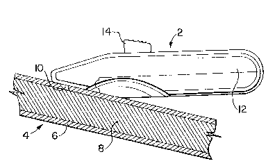
Referring now to the drawings and Figure 1
initially, it can be seen that Figure 1 illustrates a
side elevation view of the cutter tool 2, cutting the
sheath on a conductor cable 4. It can be seen that the
conductor cable 4 is constructed of a multitude of
conductor wires or strands 8, which carry telephone
messages, or the like, all of which is protected by an
outer sheath 6 of a given thickness. The cutter blade
10 extends a precise distance from the end of the cutter
tool 2, such that when the toll rides on the surface of
the sheathl tool 2 slits the sheath 6 only and does not
damage the underlying conductor wires or strands 8. The
cutter tool 2 is constructed of a handle 12, with a
blade control knob 14 extending from the top of the
.
iL~7~i2~
handle 12. The cutter tool 2 is drawn along the cable 4
in a rightward and slightly downward direction, as seen
in Figure 1.
Figures 2, 3 and 4 illustrate respectively a
top view, a side view, and a bottom view of the cutter
tool 2. Referring specifically to Figure 2, it can be
seen that the tool 2 is constructed with a nose 16,
which is relatively narrow compared to the top of the
10 handle portion 28. The handle 28 has a knob slide slot
18 formed in the top thereof. The blade control knob 14
can slide forwardly or rearwardly in knob slide slot 18.
Figure 3, which illustrates a side view of the cutter
tool 2, demonstrates that the top portion of the hanclle
lS is con~tructe~ oE a top piece 28, and a bottom piec~ 30.
Finger ~nd ~humb grips 20 are fashioned in the undersid~
o~ the cutter tool 2. As seen in Figure 4, which
illustrates a bottom view of the cutter tool 2, a blade
slot 22 is located in the nose 16 portion of the tool.
20 Thumb and finger grips 20 are also visible. The bottom
piece 30 is secured to the top piece 28 by means of a
screw 24.
Figures 5 and 6 illustrate respectively a
25 bottom view and a side view of the top piece 28. Blade
slot 22 in nose portion 16 is shown in Figure 5. Blade
tab slide slot 18 is also illustrated. Screw hole 26,
which is adapted to receive screw 24, is located in the
wider portion of top piece 28. A portion of the finger
30 and thumb grips 20 is also visible in Figures 5 and 6.
Figures 7, 8 and 9 illustrate bottom, side and
top views of the bottom piece 30. Figure 7 illustrates
f screw 24, and a portion of finger and thumb grips 20.
35 The shape of finger and thumb grips 20 in bottom piece
30 are formed so as to meet smoothly with the
1~716;~:4
corresponding portions of the thumb and finger grips 20,
which are formed in top piece 28. A lip 31, iS formed
in the upper front portion of bottom piece 30, and fits
within lip receptacle 33, which is shown in Figures 5
and 6. The lip 31, receptacle 33 combination ensures
that the bottom piece 30 is maintained in proper
relationship with top piece 20, when screw 24 is
securely tightened. Screw receiving hole 26 is
illustrated in Figure 9. Figure 9 also illustrates an
extension 32 of blade slot 22, which holds the blade 10,
and enables it to be moved back and forth from a
retracted to an extended position.
Fl~ures 10 an~ ll illustrate in detail, by
means of cutaway side view, the manner in whlch the
blade 10 can be moved from a retracted to an ext~nded
position. In Figure 10, b~ade 10 is shown in a
retracted position, as moved to that position by knob
14. A coil spring 34, shown in extended position, is
positioned in spring-blade holder barrel 40. In Figure
11, the coil spring 34 is illustrated in compressed
condition, when knob 14 has been moved to a forward
position, and thereby moves blade 10 so that it is in an
extended position. Cutting point 36, in this extended
position, protrudes from underneath the nose 16 a
specified distance as determined by blade abutment 38.
The extent to which cutting point 36 extends from the
cutter tool can be adjusted by either machining away a
portion of abutment 38, or filing or cutting away a
portion of the end of cutting point 36. In North
American industry sheath covered conductor cables tend
to have sheaths of uniform dimensions so once the
distance of protrusion of cutting point 36 is properly
set, the same cutting tool can be utilized for slitting
the sheath from all standard conductor cables of a given
; type and dimension. Cutting blade 10 slides backwardly
- 10 ~
~ 7~6~"~
and forwardly in blade slot extension 32, as shown in Figure 11.
In Figure 12, elements a, b, c, d and e, illustrate the
manner in which the blade control knob 14, is connected to the
5blade by means of blade holder 42, which receives the top portion
of blade wing 48, of cutter blade 10 ~see element e) of Figure
12). The blade holder 42 is constructed generally of a cylindri-
cal shape, and thereby fits within and slides backwardly and
forwardly in spring-blade holder barrel 40, which is machined or
10ca~st in top piece 28. Blade holder 42 has protruding from the
~ top portion thereof a wing 44, upon which knob 14 is secured.
; The underside of blade holder 42 has formed therein a blade wing
slot 46, which receives blade wing 48 of cutter blade 10. The
construction of blade holder 42 enables the cutter blade 10 to
15meet with knob 14, and thereby enables the user of the cutter
tool 2, by pushing the knob 14 backwardly or ~orwardly, to move
the cutter blade from an extended to a retracted po~ition, and
vice versa.
20Figure 13 illustrates a variation of the cutting tool
wherein an adjustable screw 50 is fitted in a threaded hole 52
in the end of the tool. The screw 50 can be positioned to
control the distance that the blade point 36 protrudes from the
end of the tool.
As will be apparent to those skilled in the art in the
light o~ the foregoing disclosure, many alterations and modifica-
tions are possible in the practice of this invention without
departing from the spirit or scope thereof. Accordingly, the
t 30scope of the invention is to be construed in accordance with the
substance defined by the following claims.