Note: Descriptions are shown in the official language in which they were submitted.
~1.~7~
Arrangement for peritoneal dialysis
and connector therefor
This invention relates to an arrangement for peritoneal
dialysis and a connector therefor.
As is known, patients with kidney diseases in the final
st-age of their illness can be kept alive only with the
aid of hemodialysis or peritoneal dialysis. Recently,
peritoneal dialysis has again become the predominant
technique because a method has been developed which can
be carried out co~tinuously and ambulant. In this so-
called CAPD method (continual ambulant'peritoneal dialysis)
in contrast to hemodialysis, in which the patient at inter-
vals of two to three days must be connected to a hemo-
dialysis apparatus with an extracorporeal blood cycle, a
catheter is implanted in the peritoneum of the patient,
the end of said catheter projecting through the abdominal
wall. Said end is connected during the peritoneal dia-
~ysis at certain intervals to a bag which contains a
sterile dialysis solution.
Normally, the metabolism products to be separated by the
kidneys, such as urea and the like, are withdrawn thro~gh
the dialysis solution dialytically through the peritoneum
which is thu~ employed as semipermeable membrane. The
connection of the bag with the dialysis solution to the
catheter is via a connector, a female connector piece
remaining permanently connected to the catheter and being
carried by the patient and a male connection piece adapted
.
-- 1~7~9
to be connected in sterile manner to the female connector
piece being disposed at the end of a length of flexible
tubing of a bag filled with the dialysis solution concerned.
In the two-bag system according to the preamble the used
dialysis solution is drained from the peritoneum in that
between the male connector piece and the filled bag a
Y piece is arranged in such a manner that at the free
connection of the Y piece an empty bag can be connected.
Between the female connector piece and the abdomen entrance,
between the Y piece and the peritoneal catheter and bet~7een
the Y piece and the empty bag, in each case a shutoff
member is disposed for example in the form of a roller
clamp. By corresponding closing and opening of said
roller clamp the following fluid passa~es can thus be
opened and closed:
From the full bag through the connector to the peritoneum;
from the full bag through the connector to the empty bag;
and from the peritoneum to the empty bag.
bsolute sterility is one of the most important basic
requirements when carrying out a CAPD to avoid infections
due to germs introduced. On the side of the male connector
piece which is connected via the flexible tube to the full
bag no problems are encountered in this respect because
the male connector piece can be made in sterile manner
with the full bag in a unit and packed sterile and disposed
of after being used once or sterilized between two uses
if the flexible tuhe member can be separated from the bag.
However, the female connector piece, which is permanently
connected to the peritoneal catheter and consequently must
be carried by the patient on the body, requires thôrough
disinfection before and after each dialysis and this is
achieved for example in that with the connection between
the female connector piece and the Y piece closed the
. .
3-
.,~,,
,' '" ''" , '
7~L67~
female connector piece is filled or i.njected with a suitable
disinfectant and thereafter sealed with a cover closing
in sterile manner. These disinfectants are not always
physiologically neutral and consequently prior to the
dialysis operation a thorough flushing of the female
connector piece is necessary and this is achieved for
example by conducting fresh sterile dialysis solution from
the full bag with the connection between the Y piece and
the peritoneal catheter closed firstly via the connector
and the Y piece into the empty bag so that the disinfectant
in the female connector together with any residual particles
which can form when the full bag is opened (for example
by breaking a breakage cone) are flushed into the empty
bag.
The prob].em a.r.ises here that i.n the connec~lon of the Y
piece leading to t:he peritoneal cathe~er a certai.n dead
space remains via which the di.alysis solution flows from
the full bag towards the empty bag so that residues of
disinfectant or particles and entrained germs can remain
in this region, which is very difficult to flush. Thus
to ensure a satisfactory flushing of the entire system
flushing must be carried out for a relatively long time
with abundant dialysis solution. This unnecessarily lengthens
the overall dialysis operation and causes a considerable
consumption of dialysis solution for pure flushing purposes.
A means of this type according to the preamble is known
from EP-OS 29 526 which comprises a simple unprotected
connector in which two connector pieces to be contacted
with the fingers are plugged. Said connector pieces each
have a joining piece for flexible tubing one of the two
connector pieces comprising additionally a further connec-
tion which thus branches in Y-shaped manner from the main
fluid passage. In this respect this arrangement thus
does not differ from the arrangement described above so
--4--
.
. .
~7~
,
01 tha-t in the tubing system dead spaces remain or residues
02 of disinfectant and ~his is not without risk to the
03 patient.
04 Furthermore, German utility model 7,834,790 and EP-OS 116
05 986 disclose connectors for peritoneal dialysis which
06 however each have only one connection, i.e. in the
07 connected state do not permit flushing or remo~al of
08 dialysis solution.
09 The present invention is thus an advance on the
previously described arrangement, and a connector
11 therefor, so that a sterile connection and flushing of
12 the entire tubing arrangement and the connector free from
13 contamination are possible. One embodiment of the
14 invention is an apparatus for peritoneal dialysis
comprising a connector having a first connector piece
16 with an introduction opening and a second connector piece
17 with a central tube section which is introducible into
18 the introduction opening of the first connector piece. A
19 first connection is located on one of the two connector
pieces for connection to a first flexible tube portion
21 which is connected to a first bag containing dialysis
22 solution. A second connection is located on the other
23 connector piece for connection to a second flexible tube
24 portion which is connectable to a peritoneal catheter. A
third connection is located on one of the two connector
26 pieces for connection to a third flexible tube portion
27 and a second bag. At least two clamps clamp off the
28 ~irst and third flexible tube portions. The central tube
29 section of the second connector piece is engaged and
surrounded by an outer sleeve. The first connector piece
31 is surrounded on its outer surface by an annular seal
32 which with the inner face of the outer sleeve forms an
33 arrangement sealing the interior of the connector. A
34 third connection originates from the outer sleeve.
In accordance with another embodiment, a male coupling
36 apparatus for a two-bag peritoneal system is comprised of
37 a connector having a first connector piece with an
38 - 5 -
3L~7~ i'f~
. ~
Ol introduction opening and a second connector piece with a
02 central tube section which is introducible into the
03 introduction opening of the first connector piece. A
04 first connection on one of the two connector pieces is
05 provided for connection to a first flexible tube portion
06 which is connected to a first bag containing dialysis
07 solution. A second connection is located on the other
08 connector piece for connection to a second flexible tube
09 portion which is connectable to a peritoneal catheter. A
third connection on one of the two connector pieces is
ll located for connection to a third flexible tube portion
12 and a second bag. At least two clamps are provided for
13 clamping off the first and third 1exible tube portions.
14 The central tube section is surrounded and engaged by an
outer sleeve, and which is in flow connection with a first
16 connecti.on disposed on the outer sleeve. A further
17 connection i9 provided on the outer sleeve for connection
18 to a second bag.
19 The Y piece with all its disadvantages is dispensed with
in that a third connection for the empty bag for receiving
21 the flushing liquid or used dialysis solution is arranged
22 on the male connector piece separate from the connection
23 for the fresh dialysis solution.
24 Advantageously, the female connector piece comprises a
shutoff member which normally closes the fluid passage
26 from the full bag to the peritoneum. Thus, by this
27 shutoff means in the first phase of the connection of the
28 male and of the female connector piece a closed space is
29 created which has a supply (from the full bag) and a
discharge ~to the empty bag) and is partially filled with
31 the disinfectant which is disposed in the female connector
32 piece above the shutoff member. In this first phase the
33 central tube section of the male connector piece does not
34 yet open the shutoff member. An opening of the full bag,
for example
36 - 5a -
~ ~7~ 79
by ~reaking a breakage cone of a closure means in the
connecting line now effects that fresh dialysis solution
from the full bag enters the closed space through the
first connection. Disinfectant and particles in this
closed space are now flushed by the inflowing fresh dia-
ly~ing solution through the third connection on the male
connector piece into the empty bag. Since said closed
space is bordered all round by plane surfaces, no dead
spaces remain in which residues of the disinfectant or
germs can remain for any appreciable time and consequently
the removal of the disinfectant and flushing of said space
is effected with a minimum expenditure of time and flushing
solution.
To prevent the ~ormation of dead spaces in the conllector
the female connector piece advantageously comprises in
the region of its introduction opening, i.e. in tlle region
which is introduced into the male connector piece, a seal-
ing member which is disposed in the immediate vicinity of
the introduction opening so that the closed space forming
when the female and male connector piece are introduced
into each other is substantially free from undercuttings.
The respective subsidiary claims contain advantageous
further developments of the invention.
Further details, features and advantages of the present
invention will be apparent from the following description
of an embodiment with the aid of the drawings, wherein:
:;
Fig. 1 is a schematical sectional view of the essential
components of the two-bag system according to the
invention;
--6--
~l~7~7~
.
Fig. 2 shows a first connecting phase of the female connec-
tor piece and the male connector piece in which
the flushing operation takes place;
Fig. 3 shows a second connecting phase of the female
connector piece and the male connector piece in
which the used dialysis solution flows from the
peritoneal cavity into the empty bag, and
Fig. 4 shows the same connecting phase as in Fig. 3 but
in this position fresh dialysis solution is flow-
ing from the full bag into the peritoneal cavity.
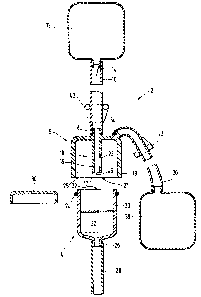
As apparent from Fig. 1 a two-bag system 2 comprises
essen~l~lly a fema]e conneclor piecea 4 and a male connec-
tor piece 6 which arc shown sepal-atcd from eacll o~her ln
Fig. 1. The male connector piece 6 is constructed as
cylindrical component sealed on one side and comprises at
its sealed end a first connection 8 for a supply line 10
which is connected to a bag 12 with fresh dialysis solution.
In the supply line 10 in the region of the bag 12 a closure
member 14 is provided which can be opened and which seals
the bag with respect to the supply line and can be opened
when required, for example by breaking off a breakage
portion.
As apparent from the drawing, the first connection 8 extends
from the outer side of the male connector piece 6 coaxially
to said male connector piece 6 in the form of an inner
tube section 16 into a receiving region 18 which is pro-
vided between the tube section 16 and a protective sleeve
19 which engages round and over said tube section 16.
The front region 17 of the tube section 16 is spaced far
enough away from the edge region of the protective sleeve
to ensure that no contact is possible. Furthermore, at
least one radial opening 23 is provided preferably adjacent
the front region 17 of the tube section 16. The connection
--7--
. ~ ~, . ..
~1~7~679
of the supply line 10 to the first connection 8 can be
effected in usual manner by shrinking on, adhering, a
Luer connection, a clamp or the like.
In accordance with Fig. ] the female connector piece 4
comprises a hollow cylindrical introduction portion 20
comprising an introduction opening 22. The external dia-
meter of the introduction portion 20 is so dimensioned
that the female connection piece 4 can be introduced with
slight clearance into the receiving region 18 of the male
connector piece 6. To obtain a liquid-tight connection
between the female connector piece 4 and the male connec-
tor piece 6 in the connected state, directly adjacent the
introduction opening 22 of the female connector piece 4
an annular sealing rnember 24 is disposed which is con-
structed for example as O ring. At the side of the female
connector piece 4 opposite the introduction opening 22 a
sccond connection 26 is formed with which the female
connector piece 4 is connectable via a supply line 28 to
a peritoneal catheter not illustrated in the drawings.
The introduction opening 22 of the female connector piece
4 is sealed with a removable cap designated by 30 in Fig.
1 when no peritoneal dialysis is being carried out. As
apparent in Fig. 1, the female connector piece 4 thus has
a hollow cylindrical form of substantially circular cross-
section, the one end comprising the introduction opening
22 and the other end being tapered -towards the tube connec-
tion 26.
Furthermore, the radial opening 23 can also extend from
the front region 17 to form one or more slots in the tube
section 16 to the connection ~, retaining its function.
In the female connection piece 4 between the introduction
opening 22 thereof and the second connection 26 a closure
member 32 is disposed which under adequate mechanical
-8-
:,, , ., .: ' . ...
~.~71~
.
load opens in the direction towards the second connection
26 and frees a fluid passage from the introduction opening
22 to the second connection 26. Said closure member 32
may for example be a valve plate having a star-shaped slot
as described for example in DF-OS 3,210,148 of Applicants.
The male connector piece 6 comprises a third connection 34
advantageously in the region of the first connection 8 to
which a supply line 36 to an empty bag 38 is connectable
or connected The empty bag 38 serves to receive the used
dialysis solution from the peritoneal cavity or to receive
the flushing solution from the full bag 12. In the vicinity
of the male connector piece 6 both on the supply line 10
and on the supply line 36 a shutoff member 40 and 42
respectively is disposed. Said shl1-toff members 40 and 42
are Eor example in the Eorm of roller or pinch clalnps and
serve to open or shut off the fluid flow through the line
10 or the line 36 respectively.
.
Hereinafter, with particular reference to Figs. 2 to 4 the
use and mode of operation of the present two-bag system
will be described.
When a patient must be subjected to peritoneal dialysis
the cap 30 is removed from the female connector piece 4
so that the introduction opening 22 of the female connector
piece 4 is exposed. The region above the closure member
32 is normally filled with a disin`fectant, or the latter
is injected thereinto, which prior to introduction of
fresh dialysis solution is to be flushed out of the full
bag 12 into the empty bag 38. For this purpose, after
removal of the cap 30 from the female connector piece 4
the female connector piece 4 is introduced into a receiving
opening 21 of the male connector piece 6 in such a manner
that a first connection state according to Fig. 2 is
reached in which the O ring 24 of the female connector
piece 4 bears sealingly on the inner peripheral wall 25
_g_
' ~ .
. .:
of the protective sleeve 19 of the male connector piece
6 so that a closed space 44 results which is defined by
the inner wall of the male connector piece 6, the O ring
24 and the closure member 32. The introduction of the
female connector piece 4 into the male connector piece 6
up to the first connection state thereof shown in Fig. 2
may for example be supported and secured by a screw con-
nection or the like not illustrated in the drawings. It
is pointed out that in the first connection phase the
front region 17 of the tube section 16 does not open the
closure member 32.
Thus, in the first connection state according to Fig. 2
the inner tube 16 o the male connectoL piece 6 e~tends
into the introduction opening 22 of the female conl-ector
piece 4 in such a manner that a mouth opening 46 in the
tube section 16 is disposed within the introduction open-
ing 22 and above the closure member 32.
Said first connection state according to Fig. 2 is re-
ferred to as flushing position.
Before discharge of the used dialysis solution from the
peritoneal cavity into the empty bag 38 and before supply-
ing fresh dialysis solution to the peritoneal cavity from
the full bag 12 a flushing operation is carried out, in
particular to remove disinfectant from the closed space 44.
For this purpose the two roller clamps 40 and 42 at the
supply lines 10 and 36 are opened so that a free fluid
passage is established from the closure member 14 at the
full bag 12 to the empty bag 38. Thereafter the full bag
12 is opened by breaking off the breakage cone portion
from the closure member 14 and fresh dialysis solution
flows out of the bag 12 through the supoly line 10 and
the inner tube 16 to the radial opening 23 and to the
mouth opening 46 of the tube section 16 and through the
--10--
closed space 44 the third connection 34 and the supply
line 36 into the empty bag 38 as indicated in Fig. 2 by
the flow arrows.
The disinfectant in the closed space 44 and particles
formed on opening the closure member 14 are thus flushed
by the fresh dialysis solution from the full bag 12 out
of the closed space 44 into the empty bag 38. The effective-
ness of the flushing operation is increased in that firstly
the mouth opening 46 of the tube section 16 is disposed
closely above the closure member 32 so that the flushing
solution completely fills the closed space 44 and e~pels
the disinfectant throuyh the third connection 34 into the
empty bag 38. On the other hand, the open diameter of
the Lube section 16 or the mouth openlngs 96 is prefeI-ab]y
grea~er than the op~n diameter of the thlrd connectlon 34
so that a pressure flushing of the closed space 44 is
eEfected by the resh dialysis solution from the full
bag 12.
By the arrangement of the O ring 24 in the immediate
vicinity of the introduction opening 22 of the female
connector piece 4 in the closed space 44 substantially
no dead space and no undercutting results in which dis-
infectant can remain and consequently a thorough and above
all a rapid flushing of the closed s?ace 44 is ensured.
After completion of the flushing operation the used dia-
lysis solution is drained from the peritoneal cavity of
the patient. For this purpose firstly the roller clamp
40 in the supply line 10 is actuated in such a manner
that the supply of fresh dialysate from the full bag 12
to the closed space 44 is interrupted. The roller clamp
44 of the supply line 36 to the empty bage 38 remains
open. Thereafter the female connector piece 4 is intro-
duced by screwing or pushing further into the receiving
--11--
~ 7~
region 18 of the male connector piece 6 until a second
connection state according to Fig. 3 is reached.
As apparent from Fig. 3 the front region 17 of the tube
section 16 opens the closure member 32, the latter being
forced in the direction towards the second connection 26
of the female connector piece 4. The radial opening 23
in the tube section 16 is advantageously far enough away
from the front region 17 to ensure that no occupation ob-
structing the 1uid passage is possible through the closure
member 32 via the connection 34. Thus, a flow connection
is established from the tubing 28 through the connection
26, the opened closure member 32, the mouth opening 46 and
the radial opening 23 of the tube section 16 to the tubing
36 and the empty bag 38 or connection 8. AJong this flllid
passage the used dialysis solution now ilows from the
peritoneal cavity oE ~he patient through the connector 2
into the empty bag 38 as illustrated in Fig. 3 by the flow
arrows, the closure element 40 rernaining closed.
This second connection state of the female connector piece
g and the male connector piece 6 is referred to as inlet/
drain position.:
When the used dialysis solution has been completely drained
from the peritoneal cavity of the patient, the roller
clamp 42 of the supply line 36 to the empty bag 38 now
~ filled with the used dialysis solution is closed so that
; the connection between the peritoneal cavity and the empty
bag 38 is interrupted.
Then, in accordance with Fig. 4 the roller clamp 40 o
the supply line 10 is opened so that a fluid passage is
freed from the full bag 12 through the male connector 6
and the female connector 4 to the peritoneal cavity of the
patient. The position of the female connector 4 within
- -12-
~L ~i~ 7 ~ ~i 7 ~
the male connector 6 corresponds largely to the second
connection state according to Fiq. 3, i.e. the closure
member 32 is open in the direction towards the second
connection 26 wi-th deformation so that the mouth opening
46 of the inner tube 16 is in flow connection with the
tubing 28. Thus, fxesh dialysis solution can pass un-
restricted from the full bag 2 into the peritoneal cavity
of the pa-tient as indicated in Fig. 4 by the flow arrows.
When the content of the full bag 12 has flowed into the
peritoneal cavity of the patient the male connector piece
6 is disconnected from the female connector piece 4, the
first conr,ection sta-te according to Fig. 2 then first being
reached again in which the closure member 32 has again
returned resiliently to its starting position so that the
access to the peritoneal cavity of the patient is again
closed. Thereafter the final disconnection of the female
connector piece 4 from the male connector piece 6 is
effected. A suitable disinfectant is introduced or injected
into the free space above the closure member 32, whereupon
the introduction opening 22 of the female connector piece
4 is again closed with the disinfected or sterile cap 30.
Advantageously, the full bag 12, the supply line 10, the
male connector piece 6, the supply line 36 and the empty
bag 38 are made and packed sterile as a unit so that no
problems are encountered in keeping the male connector
side germ-free. Such a unit is preferably surrounded by
an evacuated protective envelope in the form of a sterile
protective bag as described in European patent 50 255.
After use of this unit, i.e. after completing the dialysis,
the male connector piece and the bags 12 and 38 connected
thereto are discarded or destroyed.
In a further embodiment the central tube section 16 of the
male connector piece 6 has no radial opening 23. In this
-13-
~716791
case the closure member 32 opens to form a first flow
connection which as mentioned above leads directly through
the central tube section 16 and a second flow connection
leading past said tube section 16 through forming slots
and the like in the closure member 32 into the space 44.
The selection of the materials for making the two connector
pieces and the corresponding supply lines is within the
scope of the expert; for example, physiologically neutral
plastics or metals can be used.
-14-