Note: Descriptions are shown in the official language in which they were submitted.
~L;;'7;~ti~
TRANSDUCER PASTENING DEVICE
BACKGROUND OF THE INVENTION
Previous oil pressure transducers have utilized a two-part housing capturing a
flexible diaphragm member ~herebetween. Typically, the diaphragm is movable in
response to the pressure of the engine oil so as to operate warning switch means. The
switch means are connected into a warning circuit so that when oil pressure falls below a
desired minimum level, a warning light or the like is activated. The two-part housing is
normally joined together with the aforementioned diaphragm therebetween by means of
an edge rolled portion of one housing over the other housing in a mechanically deforming
operation.
In addition to using an edge roll type of connection, retaining rings or annular
members have been utilized to connect transducer housing portions together. This is also
an effective means of joining the housings. However, in some applications, the radial
space about the housings is quite limited and it is undesirable to utilize a retaining
device which does not project outwardly from the housing. Accordingly, the present
transducer incorporates annular split rings with portions which are expandable in the
radial direction and interfit into housing grooves. Specifically, the present oil pressure
transducer utilizes a retaining ring with a generally V-shaped cross sectional
configuration. The V-shaped legs of the retainer cooperate with aligned circumferential
grooves, one formed along the outer diameter surface of the inner housing and the other
formed along an inner diameter surface of the outer housing. The V-shaped retainer may
be conveniently inserted through a small radial space between housin~ members. This
causes the legs of the "V" to flex inward toward one another as the fastener slips into the
radial space between the housings. When the V-shaped retainer fully enters the radial
space, the leg portions of the "V" expand radially to engage axially facing shoulder
portions formed by the aforementioned channels Thus, the housings and the V-shaped
retainer is prevented from relative axial movement.
3 ;~ . 3
Previous oll pressure transducers have utilized a base housing portion
includin~ a threaded male end portion adapted to be received in a thrcadcd aperture of
the engine which fluidly communica~es with the lubrication system of the engine. The
prior transducers have utiiized housing bases with reJatively thick walls made by turning
and cutting a solid metal cylinder on a screw machine or the like. This produces a
relatively thick walled and heavy part. Obviously, another disadvantage of this type of
housing is the high cost in machining the housing on the aforementioned screw machine.
It has been found that a base housing can be easily ~ormed without machining and with
~hin wal!s by cold forming. However, this type of housing lacks a relatively thick wall or
a large diameter circumferential surface such as a hexagonal surface which can be
utilized to rotate the transducer by a wrench or the like. The subject application
describes a housing with a thin walled portion and with a desirable circumferential
surface ~ormed thereon defining a wrenching portion. The wrenchin~ portion is formed
by a molded elastomeric material or the like and has desirable wrenching surfaces
formed thereon. The wrenching portion may be manufactured separately and
subsequently joined to the housing by a press fit or by adhesives or the wrenching portion
may be mold formed about the base housing.
Therefore, an object of the present invention is to provide an cil pressure
transducer having two housing portions joined together with a diaphragm member
secured therebetween, the housing portions being axially secured together by means of
an annular retaining means which may be inserted into a small radial space between
overlapping portions of the two housings and subsequently extends into circumferentially
extending grooves in the housing portions.
Another object and feature of the subject transducer is the provision of t~vo
housing portions which are axially retained to each other by fastener means insertable
between overlying and slightly spaced wall portions, the fastener being a V-shaped
annular member with inner and outer leg portions, the leg portions of which are flexible
radially inward as the fastener is inserted between the housings and which, subsequently,
expand radially in the opposite direction into grooves formed in the housing portions so
-2-
11 ` ~ I
as to capture the housing portions In desired sxial overlapping relationsh
another.
Other advantageous features of the subject transducer will be more readily
apparent from a reading of the following Detailed Description of a Preferred Embodi-
ment, referenee bein~ had to the accompanying drawlngs in which preferred embodi-
ments are illustra~ed.
IN THE DRAWINGS
Fig. I is a partially sectioned and elevational view of the subject pressure
transducer with portions broken away to reveal features discussed heretofore;
Fig. 2 is a perspective view of a V-shaped retaining member shown in Fig. I;
Fig. 3 is a perspective view of a modified V-shaped retainer member like th~
retainer member shown in Fig. 2;
Fig. 4 is a perspective view of an annular member which forms the wrenchin
porti~n shown in Fig. I; and
Fig. 5 is a perspective view of a modified wrenching member which is simila
to the member shown in Fig. 4.
DETAILED DESCRIPTION OF A PREFERRED EMBODIMENT
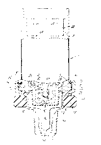
In Fig. 1, an oil pressure transducer 10 is illustrated. The pressure transduce
10 includes an upper housing portion 12 and a lower housing portion 14. The uppe
housing portion 12 has a lower end portlon 16 terrninating in a radially outwardl
extending ~lange portion 18. The lower housing portion 14 includes an enlarged diamete
upper end portion 20 which encircles the flange portion 18 of the upper housing. Th
.
~ 7i~
housing portlons 12 and 14 ~re tekscsped together and established axially ~ne to another
by means of an annular retainer ring 22 to be described in more detail hereinaf~er.
The housings 12 and 14 cooperate together to retain a generally cylindrical
sleeve member 24 or, more specifically, by contacting a radially outwardly extending
flange portion 26. The flange portion 26 of sleeve 24 also en~ages an outer periphera5
edge portion 28 of a resilient elastomeric diaphragm member 30 extending across the
hollow midportion or space 32 of the transducer. The diaphragm 30 has su~ficient
sl~rface to overlie or cover a substantial portion of a ~enerally cup-shaped end of a piston
member 34. Specifically, the end portion 36 of the piston 34 and a substantial port}on of
the lower side wall 38 of piston 34 are contacted by the central portions of the resilient
diaphragm 30. The piston 34 is biased downward toward the lower housin~ 14 by a coil
type spring 40 which rests against a shoulder portion 42 of the piston 34. The upper end
of the coil spring (not visible) rests against a recessed wall portion 44 of the upper
housing 12. An upper cylindrical side wall 46 of the piston 324 slidably engages the inner
cylindrical surface 48 of member 24.
The lower housing or base 14 is provided with thread means S0 on an end
F~rtion S2 adapted ~or threadably joining with a similarly threaded aperture s~f an engine
to mount the transducer. An oil inlet passage S4 is formed in the threaded end 52 for
communication with the engine oil lubrication system. Passage 54 in turn communicate
with the interior space 56 formed by the base 14 and the diaphragm 30. Pressurized oi
~rom passage 54 generates a force on the diaphragm 30 and, hence, on piston 34 a~ains
spring 40. This force tends to move piston 34 upward in Fig. i to a position proportiona
to the oil pressure.
The transducer includes an axially movable central stem and switc~
activatin~ portion S8 relative to sleeve 24 and housin~ 12. The lower end of portion 58 i
retained within a bore 60 of an upwardly extending tower portion 62 of the piston 34
When the piston 34 moves upward, the portion 58 is also moved therewith to produce th
aforedefined switching functions. In this regard, electrical terminals 64 and 66 ar
-4 -
'7~1il'3 ~ l l
¦¦ shown within a recess 6~ at the uppcr end o~ housing 12. The terminals 64 and 66 ~re
¦¦ adapted to be connected to an oil pressure ~arning circuit of the vehicle.
ll As preYiously sta~ed, the hou5in~ portion5 12 and 14 are secured to~ether b
¦¦ means o~ an annularly shaped retainer 22. The retainer shown in Fi~. I is bette
¦¦ illustrated in Pig. 2. The cross sectional view shows a generally V-shaped con~iguratio
¦¦ with a lower central portion 70, an inner leg portion 72 and an outer leg portion 74. Th
¦¦ leg portions 72 and 74 are resiliently connected together at the midportion 70 so that th
¦¦ leg portions may flex inwardly and outwardly to a desired extent. Referring to Fig. I
¦¦ the upper housing 12 includes an undercut portion or chann~l 76 circum~erentiall
¦¦ extendin~ in its outer surface adjacent the ~lange portion 18. I~ikewise, a similar shanne
¦¦ 78 is formed on the inside diameter portion of the end 20 of the base 14. The channel
¦¦ 76 and 78 are axially aligned when the upper and lower housings 12 and 14 are fitted i
¦¦ desired axial position. When the housings are placed in this position, the annularl
¦¦ shaped retainer 22 can be easily inserted in the 51ight radial space between surfaces 8
¦¦ and 82 of the housings 12 and 14, respectively. During insertion of the retainer 22, ~h
¦¦ inner and outer diarneter legs 72 and 74~ respectively, are fle~ted toward one anothe
¦¦ caused by the close spacing between surfaces 80 and 82. When the rnidportion 70 of th
¦¦ retainer approaches flange 18, the legs 72 and 74 then expand radially away ~rom on
¦¦ another into the channels 76 and 78, respectively. Henceforth, retainer 22 axiall
¦¦ secures the housin~ portions 12 and 14. As a result, non-destructive removal o~ th
I! retainer 22 is very diificult if not irrlp~ssible.
¦¦ In Fig. 3, a modified retainer 84 is illustrated which may be used in place o
¦¦ retainer 22 shown in Figs. I and 2. Retainer ~4 is formed from a ring or band of materia
¦¦ 86 which preferably is of metal. Alternately inwardly and outwardly projecting le~
¦¦ portions 88 and 90 are formed $rom the upper edge portion of band 86 by a series
¦¦ axially extending cuts or separations o~ the material. The cuts extend a substantia~
¦¦ portion o~ the width of the band 86 leaving a relatively small uncut lower portion whid
¦¦ 30ins the legs 88 and 90. The retainer 84 functions exactly as the retainer 22 to secur~
¦¦ the housings with its inner and outer le8 portions 88 and 90 ~eing ~lexed toward on~
¦¦ another when the retainer 84 is inserted between the surfaces 80 and 82. Likewise, th
_5_
, 11 .
l~t7;~
leg portion5 88 and 90 expand away from one another when the lower ed~e s)f re~ainer 84
approaches the i~pper surface of the flanF,e 18.
As previously stated, the ~ransducer is mounted on the ~vehicle en8ine by
rotating the base portion 14 and the threaded end portion S2 thereof to join a similarly
threaded aperture of the engine. Because the thin walls of the housing i2 and 14 are
easily crushed or damaged, it is undesirable to apply a rotating tool or wrench to the
outer surface thereof. Therefore, the transducer has wrenching portion 92 encircling the
base portion 1~. Specifkally, the wrenching portion 94 may be separately mold formed
or extrusion formed of plastic or elastomeric material and placed in encircling relation
to the circumferential surface 94 of the lower housing 14. The wrenching portion 92 may
also be iormed of sintered powder metal material if desired which is molded right around
the housing p~rtion 14 or formed separately. In Figs. 4 and 5, two embodiments of
wrenching portion 9? are shown. In Fig. 4, the wrenching portion displays an inner
cylindrical surface 96', and in Fig. 5, the inner surface displays a hexagonal surface 96"
Likewise, in Fig. 4 the wrenching portion displays a generally cylindrical outer surfac
98', and in Fig. 5, the outer surface 98" displays a hexagonal surface adapted to b~
readably engaBed by a wrench type of tool.
ln either configurations shown in Figs. 4 and 5, the wrenching portion 92 i
formed of relatively inexpensive material which is easily ~ormed by known means such
molding, extrusion or sintering. The wrenching portion 92 is secured about ~e lowe
housing or base portion 14 by either a press fit, heat shrinking the member thereon or b
utilization of some fastener such as ~rarious adhesives. The use of a diverse wrenchin
portion "ermits damaging the relatively thin walled housing, particularly in the ~ricini
of the wrenching member 92 in Fig. 1. This permits the use of various manufacturin
techniques for forming the thin walled base 149 includin~ cold forming, spinning
similar low cost forming operations as opposed to metal cutting by the use of a scre
machine or the like which is a relatively expensive manufacturing operation and produoe
relat;vely thick walls. These mamJfacturing operations are known in the art.
~ ."3
Al~hough onJy relatively few modlIications and embodirnents of th
transducer have been discussed, other nnodifications will be readily apparent to on
~killed ln the art which 5till fall wJthin the scope of the following claims ~vhich describ ,
the invention.