Note: Descriptions are shown in the official language in which they were submitted.
'7~
--1 --
~ESCRrE'~ION
___
PHYSIOLOGICAL SENSOR FOR AUTOMATIC ADJ~STMENT
OF T~IE PACING INTERVAL OF A CARDIAC PACE~MAKER
Background
_
The heart is a pump that pumps blood throughout the
body. Cardiac pacemakers have long been used to provide
stimulation pulses to the heart in order to control the rate
at which the heart pumps or beats, thereby controlling the
Elow rate at which blood is circulated throughout the body.
The principal purpose for circulating blood throughout the
body, of course, is to deliver oxygen and other nutrients to
the body cells, without which oxygen the body cells would
soon die. As the body cells are called upon to do more and
more work, the flow rate at which oxygenated blood is
delivered to the cells must be increased. This increase in
flow rate can be achieved by increasing the rate at which the
heart beats or pumps. In a normal, healthy, nonpaced
heart, the heart rate automatically increases in response to
the need to deliver more oxygenated blood to the body cells.
However, a pacemaker-contro]led heart is unable to
automatically increase its rate unless the pacemaker is able
to sense that an increased oxygen need is present.
Modern pacemakers include complex stimulation pulse
generators as well as cardiac event sensors that can pace or
sense in the atrium, the ventricle, or both the atrium and
ventricle of the heart. Further, such pacemakers include
telemetry capabilities so that the activi~y o~ the heart and
pacemaker can be transmitted to an attending physician or
cardiologist. Advantageously, such pacemakers are also
programmable so that the same telemetry capabilities can be
used by the attending physician or cardiologist in order to
adjust the control parameters associated with operation of
..
.
~L~'7;~'7~i3
2 7~843-
~the pacemaker. Such parameters not only influence the rate at
which the pacemaker's stimulation pulses are generated, but also
control the pacemaker's basic mode of operation, i.e., the heart
chamber that is paced, as well as the heart chamber that is
sensed. Hence~ modern pacemakers offer grea~ versatility in the
manner of their use. Di~sadvantageously, many modern pacemakers do
not yet have the capability to automatically adjust the pacing
rate, or pacing interval, in the absence o~ a sinus P-wave (a
sinus P-wave is explained below) as a function of the body's
physiological needs unless some sort of physiological sensor
external to the pacemaker is employed. As used herein, the term
"physiological need" includes the need to change the flow rate at
which oxygenated blood is delivered to the body's cells, as well
as okher body needs that influence the hear~ rate.
The present invention is directed to an improved
pacemaker that includes the capability of automatically adiusting
the paced heart rate as a function of sensed physlological needs
within the body. Advantageously, no electronic sensors external
to the pacemaker need be employed beyond the normal s~imulation
leads that are connected between the pacemaker and the heart. As
is explained more fully below, the present invention senses
physiological need by noting changes ln a selected tlme interval
associated with the rhythm of the heart.
Disclosed herein is a reliable method or system for
sensing a P-wave that results from an atrial stimulation pulse.
As known to ~hose skilled in the art, a P-wave is generated by the
atrium of the heart as it depolarizes. Shortly a~ter
depolarization, the atrium contracts, which contraction causes the
. . ,
i3
3 708~3-4
pumping ~unction of the atrium ~o be realizecl. While those
skilled in the art will xecognize that depolarization and
contrac~ion are separate events that do not necessarily occur a~
the same time, the term "contraction" when used hereinafter means
depolarization or an event that always occurs in synchrony with
depolarization. Because it is extremely helpful for a physician,
cardiologist, or o~her diagnostician ko know when the atrlum
depolarizeæ and contracts, and whether this depolarization is a
result of a pacemaker stimulation pulse or the result of a natural
(non-paced) rhy~hm associated with the heart, raliably sensing a
P-wave using signals sensed through the pacemaker leads,
especially a P-wave that occurs in response to a stimulation pulse
from a pacemaker, has heretofore presented a formidable challenge.
The occurrence of P-wave -- the occurrence of which represents the
depolarization of tha atrium -- is a key cardiac event ~ha~ helps
define a ~ime interval, the measurement of which is associated
with at least one embodiment of the present invention.
SU~ARY
__
It is an object of the present invention to provide a
physiological sensor that can sense when the heart rate needs to
increase or decrease as a function of the physiological
--4--
needs of the body within which the heart is located.
It is a further object of the present inven~ion to
provide a means for automatically adjusting the pacing rate
controlled by a pacemaker as a function oE physiological
need.
Still a further and related object of the invention is
to provide a means for automatically adjusting the escape
interval associated with a demand-type pacemaker, which
escape interval deEines the time interval within which a
natural heart event (such as an atrial or ventricular
depolarization) must occur in order to inhibit -the delivery
of a stimulating, pulse to the heart r said escape interval
being adjusted by the adjustment means of the present
invention so as to increase or decrease the rate at which the
heart beats in accordance with physiological need.
Yet another object of the invention is to provide a
pacemaker that includes means for selectively measuring the
time interval between a stimulating pulse applied to the
atrium or ventricle of the heart and a responsive cardiac
event, such as an atrial or ventricular depolariation or
contraction, and means for using this measured time interval
as a control parameter that adjusts the pacing rate of the
pacemaker.
A further object of the invention is to provide such a
pacemaker that further includes means for processing the
previously measured time intervals (from the the past several
heart cycles) in order to generate a reference conkrol
parameter that smoothly and safely effectuates a pacing rate
change.
A still further object of the present invention is to
provide a system and method for accurately sensing the
, .
7~ i3
occurance of a paced P-wave within the heart, that i9, Eor
sensing the depolarization of the atrium immedlately after
delivery of an atrial pacing stimulus, or or accurately
sensing the occuxance Oe a paced R-wave immediatel~ aeter
delivery o a ventricular pacing stimulus.
The physiological sensor of the present invention is
premised on the discovery that the time interval between
application of a stimulating pulse to the atrium or ventricle
of a heart and a resulting cardiac event, which event could
be either the resulting atrial depolarization or the
ventricular depolarization (which ventricular depolarization
could, in turn, be related to the depolarization that follows
an atrial depolarization or that results from a ventricular
stimulating pulse) varies as a function of the physiological
need of the body within which the heart is located. In one
embodiment, therefore, the sensor of the present invention
measures the time interval between application of an atrial
stimulation pulse, or "A-pulse," and the occurance of a
responsive atrial depolarization, or "P-wave" (the occurrence
of a P-wave indicating depolarization of the atrium). In
this embodiment, the time interval measured is designated as
the A-P interval, or API. In a second embodiment, available
for use when AV conduction of the heart is not blocked, the
sensor of the present invention measures the time interval
between application of the A-pulse and the subsequent
occurrence of a ventricular depolarization or "R~wave" (the
occurrence of an R-wave indicating depolarization of the
ventricle). In the second embodiment, the time interval
measured is designated as the A-R interval or ARI. In a
third embodiment, primarily for use with a single chamber
pacer that senses and pulses in the ventricle (or a dual
chambered pacer programmed to operate only in a single
chamber mode), the sensor measures the time interval between
application of a ventr-icular stimulation pulse, or "V-pulse,"
and the occurrance of the responsive ventricular
;;3
--6-
depolarization, or R-wave. In this embodiment, the time
interval measured is designated as the V-R interval, or VRI.
~hese and other embodiments of the invention may also measure
other time intervals measured relative to the application of
an A-pulse or V-pulse.
The physiological sensor of the present invention
therefore includes time interval measurement means for
measuring the A-P~ A-R, V-R or other designated intervals.
Preferably these interval measurements are smoothed,
averaged, or otherwise processed through appropriate
processiny means to produce a reference interval measurement
that is derived from the combined interval measurements of
the past several heart cycles. ~s such, this reference
interval measurement is free of abrupt changes, and any
established trend in the lengthening or shortening thereof
can be safely interpreted as a change in the physiological
need of the body.
The pacemaker of the present invention includes a
physiological sensor as above-described in combination with a
pulse generator; means for delivering a stimulating pulse at
a prescribed rate to a selected heart chamber; means for
sensing a cardiac event, such as a P-event or an R-event;
and means for adjusting the rate of the stimulating pulse as
a function of the derived or reference interval measurement
from the physiological sensor. In a demand-type pacemaker,
wherein a stimulating pulse is provided by the pacemaker only
when a natural cardiac event fails to occur within a
prescribed escape time interval, the present invention
adjusts the escape time interval as a function of the
reference interval measurement, and thereby effectuates the
same desired result of an adjustable pacing rate as a
function of physiological need. These escape time intervals
are typically subsets of the longer ~-V interval, and V-A
interval, the sum of which defines the pacing interval
~7-
controlled by the pacemaker. AccordingLy, the reference
interval measurement can be used to adjust the
pacemaker-controlled A-V interval, the V--A interval, or both
the A-V interval and the V-A interval, thereby controlling
the pacing rate. The reference interval measurement
generated by the present invention may also be used to
control other parameters associated with the operation of the
pacemaker in order to render the pacemaker more
physiologically responsive.
In accordance with one embodiment of the physiological
sensor of the present invention, used in conjunction with an
demand-type pacemaker, the A-P or A-~ interval measurements
are processed as follows:
At least three (3) previous heart cycles are monitored.
If an ~-pulse was inhibited more than once during the
previous consecutive three (3) cycles, then the pacing rate
does not change; iE, however, at least 3 A-pulses have been
generated and at least three API or ARI measurements have
successfully been made, then the API or ARI measurements over
these previous three cycles are examined to determine if all
are less than or greater than a reference interval
measurement, which reference interval measurement is
representative of the current pacing rate. If an increasing
or decreasing trend is noted, that is, i~ all three previous
consecutive interval measurements are moving in the same
directîon, then the interval measurement closest to the
reference interval mearurement is used as the new reference
interval measurement.
In another embodiment of the physiological sensor, the
time interval measurements may be smoothed through averaging
an appropriate number of measurements from prior cardiac
cycles.
'7~
--8--
As is evident from the above, an impoLtant
requisite Eor embodlments of the inven-tion that
measure the A-P interval is the ability to sense a
paced P-wave or stimulated atrial repolori-zation.
Conventional sensing of the P-wave using a bipolar
lead, where the same bipolar lead has been used to
stimulate -the atrium, is not possible because the
sensing amplifiers remain saturated at the time
during which -the P-wave occurs. Therefore, non-
conventional P-wave sensing means must be employed.
While various -techniques may be used to sense such a
P-wave, the preferred embodiment of the presen-t in-
vention contemplates a unipolar use of a conventional
atrial-placed bipolar lead. In accordance with this
technique, atrial stimulation occurs through unipolar
exitation of the atrium through the distal tip of the
conventional bipolar lead. P-wave sensing occurs
through unipolar sensing, ring-to-case, of the P-wave
generated by the atrium as depolarization occurs.
Utilizing the spaced-apart distal tip and ring of the
conventional bipolar lead in a unipolar mode of oper-
ation allows the P-event, occuring within a relative-
ly short time after the generation of the A-pulse, to
be accurately sensed. Alternatively, separate uni-
polar leads may be selectively placed within the
atrium, spaced one apart from the other, in order to
serve the same function. Further, for a single
chamber pacer connected only to the ventricle, these
same techniques may be used to sense the R-wave that
; 30 occurs in response to an applied V-pulse.
In accordance with one embodiment of the inven-
tion, an adaptive cardiac pacemaker for controlling
the rate at which a heart beats is provided, the
-8A-
heart beat rate cleEining a cardiac cycle durinc3 which
atrial and ventricular events occur. The pacemaker
includes: means or generating an atrial stimulation
pulse; means for delivering the atrial stimulation
pulse to an atrium of the heart in order to trigger
an atrial event; means for measuring an A-P interval,
the A-P interval comprising the time between the
generation of the atrial stimulation pulse and the
triggered atrial even-t; and means Eor adjusting the
pacemaker-controlled rate as a func-tion oE the
measured A-P interval.
Viewed from a different perspective, the invention
may be described as a means for sensing the physio-
logical need of a heart to be paced at a faster or
slower rate. More specifically, in a cardiac pace-
maker wherein the rate of delivery of stimulation
pulses to a heart is controlled at least in part by
adjusting an AV and a VA interval of the pacemaker,
and wherein the AV and VA intervals define time
periods after which stimulation pulses will be
delivered to the heart, and further wherein the heart
includes atrial and ventricular chambers through
which blood f]ows as it circulates through a body,
the physiological sensing means of the invention may
be summarized as comprisingO sensing means for sens-
ing the occurrence of a cardiac even-t, referred to as
X, subse~uent to the delivery of an atrial stimula-
tion pulse, referred to as A, generated by a pulse
generator within the pacemaker, which atrial stimula-
tion pulse is delivered to the atrium of the heart;timing means for measuring the A-X time interval
between the occurrence of the stimulation pulse A and
the occurrence of the sensed cardiac event X; and
means for controllably adjusting at least one of the
7~.;3
.
-~B-
AV or VA intervals of the pacemaker, thereby affect-
ing the rate at which the sti~ulation pulses are
delivered to the heart as a function of the A-X time
interval measured by said timing means.
~ different way of characterizing the invention is
as an improved means for adjusting the rate at which
the paciny pulses are delivered to a hear-t or are in-
hibited from beiny delivered to the heart as a
function of physiological need. In accordance with
this characterization, the invention is for use in a
pacemaker having a pulse generator Eor selectively
generating pacing pulses for delivery to a heart, and
wherein the pacemaker includes distribution means for
selectively controlling the delivery of the pacing
pulses to an atrium and/or a ventricle of the heart,
the pacing pulses thereby aEfecting the rate at which
the heart beats, and where the time interval between
successive heart beats is defined as a cardiac cycle.
The pacemaker further has cardiac sensing means for
sensing the depolorization of the atrium or vent-
ricle. In this setting, the improved physiological
rate adjusting means of the invention may thus be
described as including: timing means for measuring
the time interval between the generation of a given
pacing pulse and the subsequent depolarization or
contraction of one of the heart chambers; and means
for automatically adjusting the rate at which the
pacing pulses are delivered to or inhibited from
delivery to the heart as a function of the measured
time interval.
Still another embodiment oE the invention may be
described as a pacemaker having sensing and stimulat-
ing means coupled to the ventricle of a heart, where-
31^ `
-~C--
i.n the pacemaker includes: means for yenerating a
ventricular stimulation pulse that is delivered to
the ventricle through the stimulating means; means
for measuriny a V-R time interval, the V-R time in-
terval comprising the time between the generation ofthe ventricular stimulation p~lse and a responsive
ventricular event; and means for adjusting a pacing
rate of the pacemaker as a function of the measured
V-R time interval, the pacing rate controlling the
rate at which the heart beats.
The invention also includes a method for physio-
logically adjusting the pacing interval of a pace-
maker, the pacemaker including means for generating
an atrial or ventricular pacing pulse, means for
delivering the atrial or ventricular pacing pulse to
the atrium or ventricle of a heart, and means for
sensing the occurrence of an atrial or ventricular
event in response to the delivered atrial or ventri-
cular pacing pulse, the method comprising the steps
of: ~a) measuring the time interval between -the gen-
erating of the atrial or ventricular pacing pulse and
the occurrence of the respective atrial or ventricu-
lar event; and (b) using the time interval measured
in s-tep (a) as a control parameter to adjust the
pacing interval of the pacemaker.
Al-ternatively, the invention may be described as a
method for physiologically adjusting the pacing in-
terval of a pacemaker, the pacemaker including means
~or generating an atrial pacing pulse, means for
delivering the atrial pacing pulse to the atrium of
the heart, means for sensing the occurrence of an
atrial event in response to the delivered atrial
paciny pulse, and means for sensing the occurrence of
7~
-8D-
a ventricular event in response to the atria:L event,
the methocl comprising the steps of: (a) measuring
the time interval between the generation of the
atrial pacing pulse and a specified cardiac event;
and (b) using the time interval measured in step (a)
as a control parameter to adjust the pacing interval
oE the pacemakern
Another embodiment of the invention includes a
method for physiologically adjusting the pacing in-
terval oE a pacemaker wherein the pacemaker includesmeans for generating an atrial pacing pulse, means
for delivering the atrial pacing pulse to the a-trium
of the heart, means for sensing the occurrence of an
atrial event in response to the delivered atrial
pacing pulse, means for genera-ting a ventricular
pacing pulse, means for delivering the ventricular
pacing pulse to the ventricle of the heart, and means
for sensing the occurrence oE a ven-tricular event,
the method comprising the steps of: (a) measuring
the time interval between the generating of a speci-
-fied pacing pul.se and a specified cardiac event; and
(b) using the time interval measured in step (a) as a
control parameter to adjust the pacing interval of
the pacemaker.
Still another embodiment of the invention may be
described as a method for measuring the A-P interval
of a heart that is stimulated by a pacemaker, the
measured A-P interval being usable by the pacemaker
as a parameter indicative of physiological need. In
accordance with this embodiment, the method comprises
the steps of: (a) attaching a-trial lead means to the
pacemaker, the atrial lead means making contact with
the atrium of the heart through first and second
7~
-8E-
spaced--apart electrodes within the atri~m; (b)
electrically connecting an atrial stimulation pulse
generator within the pacemaker to said Eirst elec-
trode of the atrial lead means; (c) electrically
connecting a P-wave sensing amplifier within the
pacemaker to -the second electrode of the atrial lead
means; (d) st:imulating the a-trium with pulses gener-
ated by the atrial s-timula-tion pulse generator; (e)
monitoring the output of the P-wave sensing amplifier
to detect the occurrence of a P-wave in response to
the pulse provided in step (d); and (f) measuring the
time interval between the occurrence of one of the
pulses generated by the atrial stimulation pulse
generator and the detection of a P-wave as sensed at
the output of the P-wave sensing amplifier in step
: (e).
Yet another embodiment of the invention comprises
a method for measuring the V-R interval of a heart
that is stimulated by a pacemaker. This method in
cludes -the steps of: (a) attaching ventricular lead
means to the pacemaker, the ventricular lead means
making contact with the ventricle of the heart
: through first and second spaced-apart electrodes
within the ventricle; (b) electrically connecting a
ventricular stimulation pulse generator within the
pacemaker to the first electrode of the ventricular
lead means; (c) electrically connecting an R-wave
sensing ampliier within the pacemaker to the second
electrode of the ventricular lead means; (d) stimu-
lating the ventricle with pulses generated by theventricular stimulation pulse generator; (e) monitor-
ing the output of the R-wave sensing amplifier to
detect the occurrence of an R-wave in response to the
pulse provided irl step (d); and (f) measuring the
-8F-
-time interval between the occurrence of one of the
pulses generated by -the ventricular stimulation pulse
generator and the detection of an R-wave as sensed at
the output oE the R-wave sensing amplifier of step
(e).
BRIEF DESCRIPTION OF THE DRAWINGS
The above and other objects, features, and
advantages of the present invention will be more
apparent Erom the following more particular descrip-
-tion thereof presented in conjunc-tion with the
following drawings, wherein-
Fig. 1 is a schematic representation of a humanheart illustrating the main components thereof and
the flow of
'3~ `~
~ 9 _
blood therethou~h;
Fig. 2 is a simplified representatiOrl of the heart
showing the location of the SA and AV nodes;
Fig. 3 is a timing diagram illustrating the normal,
non-paced operation of the heart of Fig. 2 as sensed through
conventional skin ECG electrodes or equivalent;
Fig. 4 is a simplified representation of the heart
showing the manner in which a pacemaker is connected thereto
through insertion of bipolar leads into both the right atrium
and right ventricle;
Fig. 5 is a timing diagram showing the relationship
between pacing pulses delivered to the heart from a pacemaker
and the heart's response to these pacing pulses;
Fig. 6 is a timing diagram similar to Fig. 5 showing a
P-wave that occurs in response to an atrium stimulation
pulse, followed by a natural (non-paced) ventricular R-event,
and further showing consecutive A-P and ~-R time intervals
that occur over consecutive pacing intervals;
Figs. 7A and 7B are timing diagrams as in Figs. 5 and 6,
but showing some different possible sequences of cardiac
events and further defining various time intervals that are
used in the operation of a dual-chamber demand-type
pacemaker;
Fig. 8 is a timing diagram with an expanded time base
that illustrates variations of the A-P/A~R interval time
measurements that may be utilized as part of the invention;
Fig. 9A is a simplified representation of the heart
showing how a plurality of unipolar leads could be positioned
-10--
within the atrium chamber of the heart for use with the
present invention as an alternative to the atrial bipolar
lead shown in Fig. 4;
Fig. 9B is a timing diagram illustrating the sequence of
P-waves that are sensed using the unipolar leads of Fig. 9A;
Fig. 10 is a block diagram of the pacemaker system of
the present invention;
Fig. 11 is a block diagram of the physiological detector
of Fig. 10;
Fig. 12A is a flow diagram illustrating the process used
by the control logic of Fig. 11 in converting the time
interval measurement to control parameters for delivery to
the pulse generator logic;
Fig. 12B is an extension of Fig. 12A for one embodiment
of the invention;
Figs. 13A and 13B are graphs depicting illustrative
relationships between the A-P and A-R intervals and the AVD
and VAD (A-V delay and V-A delay) control parameters that
could be established by the present invention;
Figs. 14A - 14C are state diagra~s illustrating possible
operating states associated with the pulse generator logic of
Fig. 10;
Figs. 15A - 15E are further state diagrams as in Figs.
14A - 14C.
Fig. 16A is a waveform diagram illustrating the problem
of P-wave detection utilizing the atrial stimulation
electrode as the P-wave sensing electrode;
7~
Fiy 16B is a schematic eepresentation oE a user's heart
showing locations oE the atrial and ventricle electrodes;
Figs. 17A and 17B are waveform diagrams of intercardiac
electrogram (EGM~ signals, Fig. 17A illustrating an EGM
signal showing P-wave capture and Fig. 17B illustrating an
EGM signal in the absence of P-wave capture;
Fig. 18 is a block diagram of a P-wave amplifier as
shown in Fig. 10;
Fig. 19 shows frequency response curves for the P-wave
sense/amplifier and the P-wave sensing amplifier; and
Fig. 20 is a partially cut-away atrial electrode of the
type utilized in the embodiment of Fig. 10;
The following additional drawings are presented in
conjunction with that portion of the description designated
as Appendix A, wherein:
Fig. A-l is a block diagram of an alternative emobiment
of the invention described in Appendix A;
Fig. A-2 is a logic diagram of the state or programmed
timer 404 of Fig. A-l;
20Fig. A-3 depicts a preferred realization of the demulti-
plexer 414 of Fig. A-l;
Figs. A-4 and A-5 illustrate a logic diagram of the
state signal generator 406 of Fig. A-l; and
Fig. A-6 is a flow diagram of a representative program
25used to control the microprocessor 408 of Fig. A-l.
-12-
DETAILED DESCRIPTION OF T~IE INVENTION
The Eollowing description is of the best presently
contemplated mode oE carrying out the invention. This
description is not to be taken in a limiting sense but is
made mereLy for the purpose of describing the yeneral
principles of the invention. The scope of the invention
should be deter~ined with reference to the attached claims.
Before describing the present invention in detail, it
will be instructive to briefly review some fundamental
operating principles associated with pacemakers, especially
dual-chamber demand-type pacemakers. To best understand the
operations of such pacemakers, it is helpful to first have a
basic understanding of cardiac anatomy. Accordingly,
reference is made to Fig. 1 wherein is shown a schematic
representation of the heart and the flow of blood
therethrough. The heart is essentially made up of four (4)
chambers; a right atrium 11, a right ventricle 13, a left
atrium 15, and a left ventricle 17. The atrium chambers
function primarily as reservoirs into which incoming blood is
received, while the ventricles function primarily as pumping
chambers to pump the blood away from the heart to a specific
destination. Blood, carrying carbon dioxide waste from the
body cells, enters the right atrium by way of the superior
vena cava 19 or the inferior vena cava 21. At the
appropriate time, the right atrium 11 contracts and pushes
the blood through the tricuspid valve 23 into the right
ventricle 13. A short time later, -the right ventricle 13
contracts and pushes or pumps the blood through the pulmonary
valve 25, which valve leads to the pulmonary artery 27. The
pulmonary artery 27 divides into two branches, one leading to
the right lung and the other leading to the left lung. At
the lungs, the carbon dioxide in the blood is removed and
replaced with fresh oxygen. The oxygenated blood returns
from the lungs in the pulmonary vein 29, also divided into
two branches, one branch for each lung, and is deposited in
`'3
the left atrium 15. At approximately the same time that the
right atrium 11 is contracting, the Left atrium 15 also
contracts and pushes the blood through the rnitral valve 31
into the left ventricle 17. The left ventricLe 17 contracts
at approximately the same time as the right ventricle
contracts and pushes or pumps t'he blood throuyh the aortic
valve 33 into the aorta 35. The aorta is the main artery
that delivers the blood throughout the body. The natural
rhythm of the heart thus includes the contraction of the
atria, followed a short time later by the contraction of the
ventricles. The ventricles do most of the work of the
heart, as evidenced by the thickness of the heart muscle or
myocardium 37 that surrounds both the right and left
ventricles 13 and 17.
Referring next to Fig. 2, there is shown a simplified
diagram of the heart showing the four (4) chambers thereof.
For the sake of clarity, many of the elements associated with
the heart have been omitted from the drawing of Fig. 2.
Located in the right atrium 11 is an S~A node 39. The S-A
node is often referred to as the heart's natural pacemaker.
This is because the S-A node 39 begins the electrical
impulse, depicted in Fig. 2 as the wavefront 41, that spreads
in wave fashion to stimulate both the right atrium 11 and the
left atrium 15. It is this electrical impulse 41 that
causes the depolarization of the muscle tissue that forms the
walls of the atria, thereby causing atrial contraction to
occur~ Also included in the right atrium is an A-V node 43.
The A-V node 43 is stimulated by the electrical impulse 41
propagated from the S-A node 39. ~pon stimulation, and
after a short pause (typically about 0.1 seconds~, the A-V
node initiates an electrical impulse that starts traveling
down an A-V bundle 45. After a short distance the A-V
bundle 45 divides into a right bundle branch 47 and a left
bundle branch 49. These left and right bundle branches
distribute the electrical impulse throughout the myocardium
14~
or heart muscle 37, thereby causing the ventricles to
depolarize and contract.
Shown in Fig. 3 ls a representation of the various
waveforms that are generated, as sensed by skin electrodes
placed on the chest, in response to the above-described
activities. A P-wave represents the depolarization of both
atria. ~he QRS-wave, commonly referred as the QRS complex,
represents the electrical impulse as it travels from the A-V
node to the various fibers branching from the left and right
bundle branches 47 and 49 as it is distributed into the
myocardial cells, thereby causing ventricular depolarization.
The T-wave represents the repolarization of the ventricles so
that they may be stimulated again. (Note, repolarization of
the atrium is usually not sensed because it occurs about the
same time as the QRS complex, and any signals representative
of atrial repolarization are therefore masked out by the QRS
complex.) One cardiac cycle is represented by a P-wave, a
QRS complex, and a T--wave. This cycle is repeated
continuously as the heart pumps the blood as described in
connection with Fig. l. In summary, the P-wave represents
depolarization of the atria. The QRS complex, sometimes
referred to as simply an R-wave, represents the depolari-
zation of the ventricles. Depolarization/contraction of the
atria, followed a short time thereafter by
depolarization/contraction of the ventricles, are the cardiac
events that must occur if the heart is to efficiently perform
its function as a pump in distributing blood throughout the
body.
Referring next to Fig. 4, there is shown a simplified
representation of one way that an implanted pacemaker 5l may
make electrical contact with the heart. Fig. 4 depicts the
use of two (2) bipolar leads 53 and 55, each being directed
into a separate chamber of the right heart. A bipolar lead
comprises a single filar that inc1udes two (2) electrically
insulated conductors. For example, the lead 55 incLudes a
first conductor 56 that is electrically connected to a distal
tip 57 of the Lead. This distal tip is typically placed in
a cavity of the right atrium referred to as the atrial
appendage 59. A known distance Erom the distal tip 57, an
elec-trode ring 61 is electrically connected to the other
conductor 60 of the bipolar lead 55. Similarly, a distal
tip 63 and a conductive ring 65 are associated with the
bipolar lead 53 that is placed in the apex of the right
ventricle 13. The manner in which the leads 55 and 53 are
inserted into the heart, as well as the manner in which the
pacemaker 51 is implanted in the body of a patient, are well
known in the art.
Fig. 5, shows a timing diagram that illustrates the
response of the heart to stimulation pulses that are
generated by an implanted pacemaker, such as the pacemaker 51
shown in Fig. 4. In response to an atrium stimulation
pulse, or A-pulse, delivered to the right atrium 11 through
the distal tip 57 of lead 55 (Fig. 4), both atria contract
and a P-wave is generated. Because the stimulating A-pulse
originates from a different point within the right atrium
than does the normal stimulating pulse Erom the S-A node 39
(Fig. 2~, the P-wave generated in response to this A-pulse
does not appear the same as a naturally occurring P-wave.
For purposes of this application, this difference between a
P-wave in response to an A-pulse and a P-wave in response to
the naturally occurring pulse from the S-A node is depicted
as a P-wave of opposite polarity. The waveform of Fig. 5 is
further distinguished by referring to it as the Pp- wave,
indicating that it is a paced P-wave, or a P-wave in response
to a pacing signal. Similarly, in response to a stimulation
pulse applied to the right ventricle, an R-wave is generated,
represented in Fig. 5 as an inverted Rp pulse. The R-wave
in Fig. 5 is shown inverted from the R-wave shown in Fig. 3
because the stimulating pulse propagates through the
~;~,7~7~,3
`~ -16-
ventricle chamber in a diEferent direction than does the
natural stimulating pulse that propagates through the left
and right bundle branches. Hence, for purposes oE this
application, the natural responses or natural depolarizations
of the heart are represented in the Eigures as a positive
P-wave (a waveform going in the upwards direction) and a
positive R-wave. Depolarizations of the atria or ventricles
in response to an externally generated stimulation pulse,
such as occurs with a pacemaker, are represented as a
negative going Pp wave or Rp wave.
With reference to Fig. 6, one possible response to an
atrium stimulation pulse, A, is shown. As is seen in Fig.
6, in response to the pulse Al, a Pp wave form is generated a
short time later, which time interval is identified as APIl
(referring to the first A-P interval). In response to the
atria depolari~ation evidenced by the Pp wave, and in the
absence of A-V block, the ventricles depolarize and contract
without the need of a stimulation pulse. Such
depolarization occurs a time ARIl later (referrring to the
first A-R interval of the sequence shown in Fig. 6). At an
appropriate time subsequent to the generation of the first
atrium stimulation pulse Alr a second atrium stimulation
pulse, A2, is generated by the pacemaker. In response to
the A2 stimulus, a second Pp wave is generated a time API2
after the generation of the A2 pulse. Again, a naturally
occuring R-wave occurs a time ARI2 subsequent to the
generation of the A2 pulse. The AP/AR intervals shown in
Fig. 6, designated as APIi and ARIi, are time intervals that
play a key role in connection with the preferred embodiment
of the invention described herein. More particularly, it is
changes in these time intervals, when sensed after monitoring
the individual time intervals over a plurality of heart
cycles, that indicate changes in the physiological need of
the body within which the heart is located. Hence, this
particular embodiment of the invention is concerned with
i~7~:'7~
-17-
measuring the AP/AR intervals, and in processing these
measured intervals in such a fashion that the resulting
processed mearsurement can be used to adjust the control
parameters of the pacemaker in order to change the pacing
rate thereof so that this pacing rate approxiamtes the
changes that would occur in a healthy (non-paced~ heart in
response to the sa~e changes in physiological need.
Referring next to Figs. 7A and 7B there are shown
further timing diagrams that define various intervals that
are commonly used in controlling a dual-chamber demand-type
pacemaker. The description that follows is somewhat
simplified, but will be useful in understanding the operation
of a dual-chamber pacemaker. Additional details associated
woth a preferred pacemaker are described hereinafter in
connection with Figs. 14 and 15, and in Appendix B. In a
demand-type pacemaker it is common to define an escape
interval during which activity within the heart is sensed.
If a natural cardiac event occurs during this escape
interval, that is if a natural P-wave or R-wave is sensed,
then a corrresponding stimulating pulse need not be
generated. Not only does this mode of operation allow the
heart to function in its natural state, if it is able, but it
also helps conserve the limited power stored within the
battery of the pacemaker. In Fig. 7A, it is seen that both
the AP interval and AR interval are illustrated as in Fig. 6.
Also shown in Fig. 7A, however, is an AVI, or AV interval.
This is a prescribed time set by the pacemaker during which a
naturally occuring R pulse must occur, if one is to occur,
prior to the generation of a ventricle stimulation pulse, V.
As indicated in Fig. 7A, the AV interval has timed out for
the first heart cycle shown, thereby causing the V-pulse to
be generated. During the second heart cycle, however, the
AV interval has not yet timed out at the point in time when
the naturally occurring R~wave appears. Thus, there is no
need for the pacemaker to generate a V stimulation pulse
7~
- -18~
during the second heart cycle. Also illustrated in Fig. 7A
is an atrial refractory period, or ARP. During this
refractory period, the normal sensing mechanisms used within
the atrium axe nonresponsive. This refractory period is
analogous to the natural reEractory period of myocardial
tissue immediately following depolarization and prevents the
pacemaker from detecting any depolarization signals or noise
that might result in timing errors. The refractory period
is made up of two components, the absolute refractory period
(indicated by the dashed line~, during which detection of all
signals is blocked, and a no;se sampling or relative
refractory period (represented by the solid line) during
which detected signals are evaluated for a repetitive rate.
As will be evident from the discussion that follows, the
atrial refractory period, or ARP, does not prevent the
detection of a Pp pulse because, as previously stated, this
pulse is detected using a sensing means different from the
normal atrial sensing probe.
; Also shown in Fig. 7A is a VA interval, or VAI. The
beginning of this interval is initiated by the generation of
a V-stimulation pulse, or the sensing of a natural R-wave.
This VA interval, less the ARP, defines the time during which
a natural (non-paced) P-wave must be detected if the A
stimulation pulse is to be inhibited. As is evident from
Fig. 7A, the pacing interval or rate set by the pacemaker is
equal to the VA interval, VAI, plus the ~V interval, AVI.
Hence, by varying or adjusting these two time periods, the
pacing interval of the pacemaker can be controlled, thereby
controlling the heart rate.
Referring next to Fig. 7B, a different cardiac event
sequence is illustrated. In this figure, it is seen that an
A-pulse, or atrial stimulus, is first generated, causing a Pp
wave (or atrial depolarization~ to occur. The AV interval
is initiated by the generation of the A-pulse. At the
~;~'7~'7~
1 9 -
conclusion of the AV interval, a V-pulse or ventricle
stimulation pulse is yenerated because no natural occuring
R-wave was sensed prior to that time. In response to the
generation of the V-pulse, the ventricle depolari~es as
evidenced by the Rp-wave, and the next VA interval is
initiated. Before the VA interval, or VAI, terminates,
however, a natural P-wave (identified as P, and sometimes
referred to as a sinus P-wave~ occurs. Accordingly, there
is no need for the pacemaker to generate an atrium
stimulation pulse. The sensing of the P wave re-initiates
the AV interval. During this interval, the sensors in the
ventricle are monitoring the ventricle activity to determine
if a naturally occuring R-wave is present. For the
situation shown in Fig. 7~, a naturally occurring R-wave does
not occur prior to the termination of the AVI, so a V-pulse
is generated, thereby causing a paced Rp wave to occur,
indicating ventricular contraction.
It is to be understood that Figs. 7A and 7B represent
simplified timing diagrams that illustrate only two of a very
large number of heart event sequences that can occur.
Volumes have been written by those skilled in the art
describing the various heart rhythms, and abnormalities
related thereto, that may occur. While most modern
pacemakers are designed to recogniæe and deal with many of
these abnormalities, a description of such matters herein
would add little to the understanding of the present
invention. In fact, a detailed description of all the heart
rhythms and abnormalities associated therewith could
obfuscate an understanding of the present invention.
Accordingly, no such detailed description will be presented
herein beyond that which is believed necessary to fully
understand the present invention.
At this point it would be helpful, however, to review
the different type of pacemakers that are available, and with
7~7~i;3
-20-
which the present invention couLd be used. Generally,
pacemakers are identified by a three letter code. The first
letter represents the chamber of the heart that is paced.
This letter may be a V for ventricle, an ~ Eor atrium, or a D
for double ~meaning that both the ventricle and atrium are
paced). The second letter indicates the chamber sensed.
Again the possible letters used are the V for ventricle, the
for atrium, a D for double, or the number "0" for none.
The third letter indicates the mode of response of the
pacemaker. A "T" indicates a triggered mode of response
wherein the pacemaker regularly sends a stimulation pulse to
the heart. An" I" indicates an inhibited mode of response,
indicating that a stimulation pulse will be delivered to the
heart unless it is inhibited by a naturally occurring
cardiac-event that occurs within a predefined time interval.
A "D" indicates a double mode of response, wherein the
pacemaker may either operate in a triggered or inhibited
mode. It is contemplated that the third letter could also
be used to indicate the addition of the physiological sensor
of the present invention to the pacemaker. For example, if
the third letter were a "P", for "physiological", then that
could be used to signal a multimode response pacemaker that
includes automatic pacing interval adjustments in response to
the sensed change in physiological neeed. Hence, a VVP
pacer could be one in which the ventricular chamber is paced,
the ventricular chamber is sensed, and the V-R interval is
measured and used as a controlling parameter to automatically
adjust the pacing interval in accordance with the teachings
of the present invention. A DDP pacemaker, in accordance
with this marking scheme, would be the most versatile of all
modern pacemakers. This is because such a pacemaker could
not only be programmed to operate in any mode that is best
suited for the particular patient, but it would also
automatically adjust the pacing interval in accordance with
the sensed physiological need of the patient, regardless of
the chamber or chambers of the heart that are being paced or
7~
-2L-
sensed. While there are several DDD pacemakers c~rrently
available on the marlcet, .such as the AFPII 283 manufactured
by Pacesetter Systems, Inc. of Sylmar, California, none ara
yet available that include the sensing and adjustment
capabilities of the present invention. ~lowever, it is to be
understood that the present invention -- a physiological
sensor that can be used to automatically adjust the pacing
rate delivered or controlled by a pacemaker-- could be
adapted for use with any of the existing or yet to be
designed pacemakers.
There are essentially three operating modes or types of
pacemakers that are presently envisioned for use with the
physiological sensor of the present invention. These are:
1. A single chamber atrial pacemaker;
2~ A single chamber ventricular pacemaker; and
3. A dual-chamber pacemaker.
A single chamber atrial pacemaker would measure the A-P
interval and use th;s measurement to adjust the pacing
interval in an appropriate direction. A single chamber
ventricular pacemaker would measure the V-R interval and use
this measurement to adjust the pacing interval in an
appropriate direction. A dual chamber pacemaker could
measure either the A-P interval, the V-R interval, or the A-R
interval, depending upon its mode of operation, and use these
measur~ments to adjust the pacing interval in an appropriate
direction. Because the dual chamber pacemaker is the most
versatile, and because the single chamber pacemakers are
really subsets of the dual chamber pacemaker (at least
insofar as an understanding of the present invention is
concerned~, the description that follows is directed towards
a dual chamber pacemaker. However, it is to be emphasized
that the present invention is not so limited. Moreover,
where the description given hereinafter refers to the
~7~7~
-22-
mea.5urement of the ~-P intervalv it is to be understood that
these same teachings could be applied in measuring or
describing the V-R interval.
Referring next to Figure 8, there is shown a timing
diagram having an expanded time base illustrating some
variations of the A-P and A-R time intervals that could be
utilized with the present invention. Because the paced
P-wave is not a sharp pulse as are the stimulation pulses,
such as the A-pulse, it may be advantageous to terminate the
A-P interval at various points on the Pp wave. For example,
as illustrated in Figure 8, the API could terminate at the
commencement of the paced P-wave, at the peak of the paced
P-wave, or at the conclusion of the paced P-wave. As a
practical matter, the detection circuitry is the simpliest
and less costly if the peak of the P-wave is used as the
detection point. Moreover, because there may be variations
in the sensing circuitry, the peak of the P-wave may not be
consistently sensed, but some threshold on the P-wave will be
sensed with sufficient consistency for a meaningful API
measurement to be made. Likewise, the ARI measurement will
typically be made to the peak of the R-wave, designated as
ARI2 in Fig. 8, because this is the easiest signal to detect.
However, assuming that appropriate detection circuitry is
available, the leading edge, designated ARI1, or the trailing
edge, designated ARI3, couId be used in place of the peak
ARI measurement. Similarly, a detection circuit that senses
the maximum slew rate of the R-wave could be employed.
Next, referring to Fig. 9A, there is shown an
alternative embodiment of lead placement within the heart
that could be used with the present invention. In accordance
with this embodiment, a plurality of unipolar leads,
identified as leads A, B, and C, may be selectively placed
within the atrium 11 of the heart. A conventional bipolar
lead, identified as lead D, is shown as being inserted in the
~7~
-23-
ventricle 13 of the heart~ In accordance with the embodiment
shown in Fig. 9A, it is contempLated that the atrium
stimulation pulse, or A-pulse, would be delivered to the
heart through lead A. The tip of lead B/ being spaced a
fixed distance from lead A, wouLd sense the generation of the
P-wave at a certain time later, iden~ified as Tl in the
timing diagram of Fig. 9B. The time Tl i5 a function of the
propagation rate oE the stimulation pulse as this stimulation
pulse travels the distance dl in Fig. 9A. As described thus
far, it is noted that the tip of lead B in E'ig. 9A is
performing the same function as the ring electrode 61 of the
bipolar lead 55 in Fig. 4. A third lead, lead C, could also
be enployed, with its tip spaced a distance d2 from the tip
of lead B. Hence, as indicated in Fig. 9B, the Pp wave
sensed by lead C would be delayed by an amount equivalent to
the propagation delay time of the stimulation pulse through
the atrium as it travels the distance d2. It is within the
scope of the present invention that either the times Tl, T2,
Tl - T2, or Tl + T2, could be used as the timing interval
that is measured in order to determine changes in
physiological need in accordance with the present invention.
It is also contemplated that changes in the width oE the
paced P-pulse, PW~ could be used to indicate physiological
need. Further, while Fig. 9A illustrates unipolar leads
~5 placed in the atrium, and a bipolar lead placed in the
ventricle, it is to be understood that other combinations of
unipolar/bipolar leads, all unipolar leads, or all bipolar
leads (Fig. 4) could be employed. Further, a tripolar lead
having at least two spaced apart ring electrodes in addition
to a distal tip electrode could be used to achieve the
function described above.
Referring now to Figure 10, a block diagram of a~
implanted pacemaker 16 according to the invention is shown,
the pacemaker 16 being connected to a user's heart 18. ~t
appropriate times, the pacemaker 16 my be electromagnetically
. .
--~4--
in contact with a telemetry transmitter and receiver 20
external ta the user's skin 21~ A conventional bipolar
atrial lead 22 i5 provided having a first or tip electrode 24
at its distal end and a second eLectrode 26 spaced apart from
the tip electrode 24 and in the configuration of a typical
bipolar lead ring electrode. It may be understood that a
second ring electrode and an associated amplifier may be used
for greater signal strength in sensing the electrical
activity in the atrium. The tip electrode 24 is located in
lO contact with atrial tissue of the heart atrium 11. A bipolar
ventricle lead 30 is located in the heart ventricle 13 and is
attached to the pacemaker 16 through a ventricular connector
34. Of course, a unipolar ventricle lead could also be
used. The atrial lead 22 is connected to the pacemaker 16
15 through an atrial connector 36. The pacemaker 16 includes a
telemetry subsystem 40 for transmitting data and parameter
values to the external telemetry transmitter and receiver 20,
and for receiving data instructions and the like from the
external telemetry transmitter and receiver 20. The
20 pacemaker 16 also includes pulse generator logic circuitry 42
which, in turn, controls pulse output driver circuits 44 for
providing both atrial and ventricle stimulation pulses. The
atrial output of the pulse output driver circuits 44 is
connected through the atrial connector 36 to the atrial tip
25 electrode 24 for stimulation of the atrium; the ventricLe
output of the pulse output circuits 44 is connected through
the ventricle connector 34 to a ventricle tip electrode 46
for stimulation of the ven~cricle. A P-wave sense/pace
amplifier 48 havin~ bandpass characteristics as explained
30 below is also connected through the atrial connector 36 to
the atrial tip electrode 24 for receiving electrical signals
present at the electrode 2 4. The output of the P -wave
sense/pace amplifier 48 is also connected to the pulse
generator logic circuitry 42 and to switch 50, the purpose of
35 which will be explained below. The implanted pacemaker, in
operating as a "demand" type pacer, would not provide
-25~
stimulation to the atrium when ampliier 48 provides at its
output a signal indicating the sensing of an intrinsic or
sinus P-wave. A second amplifier, a P~wave sensing EGM
ampliEier 54 having bandpass characteristics as explained
below has its input connected through the atrial connector 36
to the second atrial electrode 26~ The output of the P-wave
sensing a~pliEier is also connected to the switch 50. An
~-wave sense/pace amplifier 56 is also provided, its input
being connected to the pulse output driver circuits 44, the
ventricle tip electrode 46, and a ventricle ring electrode
46a, these last two connections being made through the
ventricle connector 34. The output of the R-wave sense/pace
amplifier 56 is connected to the pulse generator logic
circuitry 42 for inhibiting a ventricle stimulation pulse in
the presense of spontaneous ventricular activity, (i.e., in
the presence of a naturally occuring, non-paced, R-wave~ and
to the switch 50. Amplifier 56 has a sufficiently broad
band-pass characteristics to pass electrical signals of
substantialy all native (intrinsic) ventricular activity.
The output of the switch 50 is connected via a line 58 to the
telemetry subsystem 40 for real time transmission of the
output of either the P-wave sense/pace amplifier 48, the
P-wave sensing amplifier 54 or the R-wave sense/pace
amplifier 56. The specific amplifier output to be
transmitted is selected by the physician via instructions
transmitted by the external telemetry transmitter and
receiver 20 and received by the implanted telemetry subsystem
40. These instructions are decoded by a decoder and encoder
60'. The output of the decoder and encoder 60' is utilized
to establish which amplifier output 48, 54 or 56 is to be
connected to the telemetry system 40 for transmission to the
external telemetry transmitter and receiver 20. Although the
switch 50 is shown as a switch, it should be readily apparent
that any kind of selectable connecting means could be
e.mployed to provide continuity between one of the amplifiers
48, 54 and 56 and the line 58. Further, two or more of the
L~7~
-26
amplifier outputs could be transmitted simultaneously if
proper provisions were made within the telemetry subsystem
20. In addition, a memory 62 is provided which receives
parameter information from the decoder and encoder 60', this
parameter information being utilized to control the pulse
generator logic circuitry 42. The tip electrode 24 for
stimulating the atrium and the tip electrode 46 for
stimulating the ventricle may be utilized in a unipolar
configuration with the return path being provided through a
conductive portion of the pulse generator case 64 which i5
connected to the pulse output driver circuits 44.
Alternatively, bipolar operation may be employed where the
return path is through the conductor connected to the ring
electrode, although such bipolar operation may make sensing
]r, of a Pp-wave difficult, as explained below. A battery 66 is
also incorporated for providing power to the implanted
pacemaker 16. It should also be recognized that although an
implanted pacemaker is shown for illustrative purposes, the
invention is in no way limited to an implanted pacemaker.
An external pacemaker could also be provided in accordance
with the teachings of the inven-tion. Further, although
bipolar atrial and ventricular leads were chosen for
illustrative purposes, a unipolar ventricular lead could also
have been utilized provided appropriate connectors were
available on the pacemaker, and a plurality of unipolar leads
could have been used within the atrium as shown in Fig. 9.
Similarly, a multi-conductor atrial lead could be provided
with two of the conductors providing a bipolar atrial lead
and the third conductor being connected to the P-wave sensing
ECG amplifier 54 shown in Figure 10.
Also included in the pacemaker 16 is an interval
measurement circuit 71 and a physiological detector 73. The
interval measurement circuit 71 comprises an appropriate time
interval measurement circuit. The time interval measured is
started by the generation of an atrium stimulation pulse as
-27-
generated by the puLse output driver circuits 44, and is
stopped by the output of either the P-wave sensing EGM
ampliEier 54 (which output indicates the sensing of a Pp
wave~, or the output of the ~ wave Sense/Pace ampLiier
(which output includes the sensing of an intrinsic R-wave~.
The interval measurement circuit therefore measures the ARL
or the API, as selected by control signals received through
the telemetry subsystem. Further, it is contemplated that
one mode of operation could include always measuring the ARI,
if present, but if not present, as for example in a situation
where heart block exists, then automatically reverting to
measuring the API.
The time interval measured by the interval measurement
circuit 71 is passed to the physiologcal detector 73, which
detector 73 processes the measured interval as described more
fully below and generates appropriate control parameters as a
result of this processing that are delivered back to the
pulse generator logic ~2.
The manner in which the implanted pacemaker 16 operates
20~ will now be explained. This explanation will be given in two
parts, a first part of which relates to the sensing function
of the pacemaker, and a second part of which relates to the
physiological detecting function of the pacemaker and the
manner in which the pacing rate is varied or controlled as a
result of this physiological detectionO Because the
telemetry ~unctions and pulse generator/pulse delivery
functions are conventional functions performed by pacemakers
known in the art, no further explanation of these functions
will be presented herein.
Sensing Func-tion
First, with reference to the sensing function of the
pacemaker, operation of the pacemaker 16 shown in Fig. 10 can
be best understood by refrence to Figures 16A, 16B, 17A and
~ ~7~
-2~-
17B. One of the problems associated with atrial pacing is
determining whether atrial or P-wave capture has been
efEected by atrial stimulation pulses. This involves sensing
the occurrence of a paced Pp wave. In prior art systems, the
sensing circuit corresponding to the P-wave sense/pace
amplifier 48 in Figure 10 sensed signals present at the
electrode at the lead distal end (corresponding to the tip
electrode 24 in Figure 10). Referring now to Figure 16~, the
voltage present at the output of the P-wave sense/pace
amplifier 48 in the presence of an atrial stimulation puLse
corresponds in general to the waveform shown at 70. Thus,
the output of the P-wave sanse/pace amplifier 48 i5 saturated
during the period "S" shown in Figure 16A. Because the paced
Pp-wave voltage is small with respect to the saturation
voltage caused by the A stimulation pulse, which Pp-wave is
represented in Figure 16A by the wave 7~, it is difficult, if
no-t impossible, to pick out the time at which the Pp wave
occurres relative to the stimulation pulse At which A-pulses
occur at the times indicated by the arrows 74. Because of
this difficulty in determining when the Pp-wave 72 actually
occurred relative to stimulation pulse occurrence as shown at
74, it is difEicult for the physician to determine if the
stimulation pulse has effected P-wave capture. It is also
difficult, if not impossible, to measure the API as is
required by the present invention.
ReEerring now to Figure 16B, a simplified representation
of the heart is shown, showing a pacemaker 76 according to
the invention, having a conventional atrial lead 78 and, also
having a stimulation and sensing electrode 80 at its distal
end and a second or Pp wave sensing electrode 82 spaced apart
from the stimulation electrode 80. By way of example only,
the atrial lead 78 is configured in the form of a J at its
distal end so that the stimulation electrode 80 can be
located within the atrial appendage (not shown~. The heart
sinus node 84 is also shown, as well as a ventricle lead 86
.
'72~
-29-
having its stimulation electrode ~8 located in the
ventricular apex. It can be appreciatec1 that the further the
sensing electrode 82 i5 spaced-apart from the stimulation
electrode 80, the less the stimulation pulses will interfere
with Pp-wave sensing by the sensing electrode 82. This is
because the electrical stimulation signal, by the time it
propagates to the sensing electrode 82, has decreased in
amplitude a sufficient amount to preclude it from interfering
with the sensing oE the Pp wave. However, it should be
~ apparent that the sensing electrode 82 cannot be so far
removed from the stimulation electrode 80 that it would no
longer be within the heart atrium. For the embodiment
shown, all electrodes 80, 82 and 88 use the case of the
pacemaker 76 as a return electrode, the case being positive
with respect to a negative going pulse present at both
stimulation electrodes 80 and 88. Another advantage of
utilizing the spaced-apart sensing electrode 82 for Pp-wave
detection is that the P-wave electrical characteristics as
picked up by the sensing electrode 82 differ because of the
direction of propagation. This is shown by the arrows 90
and 92, arrow 90 showing the propagation direction from the
; stimulation electrode 80 and arrow 92 showing the propagation
direction from the sinus node 84. As explained previously,
this propagation direction is what causes the polarity of the
two signals to be different. Further, in determining P-wave
capture, this allows the physician to determine if the P-wave
occurred as a result of spontaneous atrial activity or
stimulated atrial activity. Moreover, because o the
diferent distances between the sensing electrode 82, the
sinus node 84, and the stimulation electrode 80, it can be
appreciated that even if the sinus node 84 is operating in
synchronism with the stimulation pulses, the known
propagation time between a stimulation pulse and P-wave
generation could be used to determine if P-wave generation
were due to spontaneous or stimulated atrial activity.
Further, it can be appreciated that although a typical
~ ~ ~7~ r;~ 3
-30-
bipolar atrial electrode 78 is ut:ilized, a]l three electrodes
80, 82 and 88 operate in a unipolar manner in that they all
use the pacemaker 76 case as a common return electrode.
Alternatively, the ventricular lead 86 could be a bipola~
lead, and the sensing/pacing in the ventricle could be
operated in a bipolar manner without interferring with the
P-wave detection in the atrium.
Detection of atrial capture can be further understood in
reference to Figures 17A and 17B, which figures show actual
intercardial electrograms as sensed by an implanted pacemaker
and transmitted to a suitable display device. Referring to
Figure 17A, atrial stimulation pulses 1~0 can be seen.
Further, P-waves 104 and R-waves 106 can also be seen. The
time differential D between atrial stimulation and P-wave
occurrence in successive cycles can be seen to be constant.
Thus, the physician can assume that P-wave capture as a
result of the atrial stimulation pulses has occurred provided
that the distance D corresponds approximately to the
propagation delay due to the distance between the stimulation
electrode 80 and the sensing electrode 82 as explained in
conjunction with Figure 16B. Referring now to Figure 17B,
the time differentials D' and D" between the atrial
stimulation pulses 100 and P-wave occurrences 102 can be seen
to be different. Thus, the physician can conclude that
P-wave capture by the atrial stimulation signals has not
occurred but that the P-waves are spontaneous or "native'l or
"intrinsic" in origin. Under normal circumstances with
respect to Figure 17s, the physician would assume that the
magnitude oE the stimulation pulses is below the stimulation
threshold of the particular patient's atrium and would
accordingly increase their magnitude until P-wave capture
occurred, that is, until an EGM signal similar to that shown
in Figure 17A is observed. Again, in prior art systems, it
would be impossible to observe the presence of P-waves
utilizing the stimulation electrode 80 tFig. 16B) as the
3~"7~7~
31-
sensin~ electrode due to the saturation of the P-wave
sense/pace amplifier resulting from the atrial stimulation
pulse (see Fig. 16~).
Figure 18 shows a simplifie~ block diagram of a typical
P-wave or R-wave wave amplifier 109 such as those shown in
Figure 10 as blocks 48, 54 and 56. The amplifier 109
includes an amplification portion 110 and an input filter
112. The diEference between the P-wave sense/pace amplifier
48 and the P-wave sensing amplifier 54 i5 in the bandpass
characterisitics of the amplification portion 110 and filter
112 combination. The amplitude and bandpass characteristics
of the P-wave sense/pace amplifier 48 are chosen to provide
to the pulse generator logic circuitry 42 a positive
indication of P-wave occurrence in the absence of an atrial
1~ stimulation pulse, while at the same time rejecting
non-P-wave signals such as far-field R-wave signals and
muscle electrical noise. This is to allow the pulse
generator logic circuitry 42 to determine if the atrium is
operating spontaneously or whether an atrial stimulation
pulse is required. It is the output of this amplifier 48
that is subjected to the atrial refractory per;od discussed
previously.
The purpose of the P-wave sensing amplifier S4 (Fig. 10)
is to provide an electrogram of all, or most all, atrial
electrical activity including an indication of Pp-wave
occurrence in the presence of an atrial stimulation pulse.
Thus, the precise characteristics of the Pp-wave and its
location with respect to an atrial stimulation pulse must be
determinable in order to measure the AP interval and in order
to determine i~ the P-wave is occurring spontaneously or is
occurring as a result of an atrial stimulation pulse.
In order to meet these different requirements, the
amplifer 110 and filter 112 combination of the P-wave
-32-
sense/pace amplifier 48 as showl~ in Fi~ure 10 can be chosen
to have a center frequency at 60~1z and 3db points at approxi-
mately 10Hz and 100Hz. The purpose Oe this U-shaped
frequency response is to maximi~e detection of the intrinsic
P-wave which has a large frequency component near 60Hz and to
reject other signals such as some of that from the heart
R-wave which by the time it reaches the atrium has lower
frequency components and muscle electrical noise which has
mostly higher frequency components. Thus, the bandpass
characteristics of the P-wave sense/pace amplifier 48 must be
chosen to attenuate all electrical signals within the atrium
other than the frequencies that most characterize the
intrinsic P-wave. Of course the bandpass characteristics
described above are only representative of one embodiment,
and other response characteristics could be chosen. For
example, a response curve having a peak of between 40Hz and
80Hz and the 3db points could lie between 0.lHz and 500Hz
could be chosen. The teaching of the invention merely is
that the P-wave sense/pace amplifier 48 be chosen to pass
signals characteristic of the intrinsic P-wave while tending
to reject signals that are not characteristic of the
intrinsic or sinus P-wave. Thus peak detection circuitry in
the pulse generator logic circuitry 42 (Fig. 10) can be
triggered by the output of the P-wave pace/sense amplifier 44
without danger of a false detection due to other electrical
activity in the atrium.
The P-wave sensing EGM amplifier 54 is chosen to have a
response that is essentially flat between about 3-1/2Hz and
200Hz. This is to allow the Pp-wave to be sensed and to
allow the physician to see all electrical atrial activity for
a complete understanding of the atrial electrical environment
including any T-wave ventricle signals and any farfield
R-wave signals that are present. However, the invention is
in no way limited to a Pp-wave sensing ~GM amplifier 48
having a flat response, and a frequency response such as that
~L."~7~3~.3
-33-
of the P-wave sense/pace amplifier could also be utilized.
In particular, use of such a frequency response that impro~7es
the ability to make the necessary AP interval measurement
would be desired.
The above can be further understood by referring to
Figure 19. Here the P-wave sense/pace amplifier response
113 and the P-wave sensing EGM amplifier response 114 can be
seen. As can be seen, the response 113 is chosen to pass the
P-wave frequency and attenuate the frequencies associated
with other physiologic events as shown at 115 and 116 in
order to provide a relatively high amplitude output corres-
ponding only to R- and P-wave events. The response 114 is
chosen to pass all frequencies in order to provide an
accurate overall EGM signal to the physician. As shown,
response 114, of the sensing amplifier includes T-wave
ventricular frequencies and far-field signals. If inclusion
of these signals makes it difficult to accurately measure the
AP interval, then a narrower response, such as is indicated
by the dashed-line response 115' could be employed.
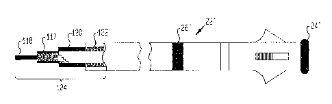
Referring now to Figure 20, a lead 22' of the type shown
in Figure 10 as 22 is illustrated. Although a straight shank
lead is shown for illustrative purposes, it should be
recognized that a typical atrial J lead could be utilized in
the application shown in Figure 10, and thus a portion of the
distal end of the lead could be J-shaped. The lead 22'
includes a tip electrode 24' which is connected through a
spirally-wound conductor 117 to a first terminal 118. A ring
electrode 26' is attached through a spirally-wound conductor
122 to a second terminal 120, this conductor 122 being
electrically isolated from the conductor 117 attached to the
tip electrode 24'. The terminals 118 and 120 are adapted to
connect to appropriate connectors in the pacemaker.
Although the connector or terminal arrangement generally
shown at 124 is a typical in-line type of connector, other
-3~-
connector arrangements could be utilized such as having each
terminal coming out of the proximal end of the lead to ~orrn a
Y-shaped connector. The ring electrode 26' is spaced apart
from the tip electrode 24' a distance such that when the tip
ri 24' is located in the atrial appendage, the ring electrode
26' will also be located within the atrium. As previously
explained, Figure 20 merely illustrates a typical bipolar
atrial lead which is utilized in the Figure 10 embodiment
while having its tip electrode and ring electrode operate in
a unipolar fashion. Thus, an implantable pacemaker con-
figured according to that shown in Figure 10 can be utilized
with conventional bipolar atrial leads without requiring a
special purpose lead to be utilized.
-35-
Physiolog,ical Detecting Function
_.
The second part of the manner in which the implanted
pacema~er 16 (Fig. 10) operates will now be explained. This
part relates to the physiological detecting function of the
pacemaker and how the pacing rate is varied or controlled as
a result of this physiological detection. Referriny back to
Fig. 10, the interval measurement circuit 71 can be realized
using any suitable counting circuit that is started and
stopped in the manner previously described. This counting
circuit may be clocked by an appropriate high frequency
signal (not shown~ that is derived from the system clock used
within the pulse yenerator logic 42. Once an interval
measurement is made, this measurement is directed to the
physiological detector 73.
Referring next to Fig. 11, there is shown a block
diagram of a hardwave implementation of the physiological
detector 73 of Fig. 10. As an alternative, the function
performed by the detector 73 shown in Fig~ 11 could be
realized using a microprocessor that is controlled by a
~,o program stored in ROM (read only memory) or in RAM (random
access memory). An advantage of using RAM is that program
optimization for a particular patient is possible using
telemetric transfer of data via link 40 in Figure 10. Such
an alternative embodiment is briefly described in Appendix A,
,5 attached hereto. As indicated previously, the interval
measurement circuitry 71 of Fig. 10 measures the A-P
interval, the A-R interval, or (for single chamber
ventricular pacing~ the V-R interval. For purposes oE the
discussion that follows in connection with Figures 11 and 12,
this interval measurement will be generically referred to as
the A-X interval measurement, where X refers to either the P
(for the A-P interval measurement) or the R (for the A-R
interval measurement), and where it is understood that the
V-R measurement is processed similar to the processing of the
A-X measurement, and where it is understood that a V-R
t~ t~
-36-
measurement is included within the "A-X" designation for
purposes of the description that ~ollows.
The A-X interval measurement is loaded into a first-in,
first-out, or ~'O register 201. The sequencing of the A-X
value through ~IFO 201 is controlled by clock signals, such
as a clock corresponding to the pacing interval obtained from
the pulse generator logic 42 (Fig. 10). Any signal that
occurs d~lring every heart cycle, such as the A-V delay, or
AVD signal, could be used for this purpose. The FI~O 201
includes the capacity to hold at least three A-X interval
measurements. Each measurement thus held is accessible
through a multiplexer 203, the output of which is directed to
a holding register 205. The contents of the holding register
205 may be directed to a comparision circuit 207 or through
select logic 209 to an A-X reference register 211. The
comparison circuit 207 compares the contents of the holding
register 205 with the contents of the A-X reference register
211 and sends the difference between the value stored in
these two registers to a difference register 213. The
~O contents of the difference register 213 are available to
control logic 215, as are the contents of the A-X reference
register 211. Also included as part of the physiological
detector 73 is a memory table 217. While the memory table
217 is shown in Fig. 11 as actually being inside of the
~r, physiological detector 73, it is understood that this memory
table could also be located within the ~emory circuits 62
shown in Fig. 10. Stored within the memory table are a range
of values for the ~-X interval. Corresponding to each of
these stored values is a corresponding value for the V-A
delay, or VAD, and the A-V delay, or AVD. As will be
described below, the VAD and AVD comprise the principal
timing ele~ents of the AV and V~ intervals, which intervals
define a pacing interval. Accordingly, by adjusting the
values of the VAD and AVD, the pacing interval delivered by
~5 the pacemaker to the heart can be controlled. The control
-37
logic 215 includes poi~ter control circuitry that allows it
to scan th~ A-X values stored in the Memory T~ble 217. The
stored value of A-X at any given point or location within the
memory table 217 may be transferred throuyh select logic 209
to the A X reference register 211. Similarly, the VAD and
AVD values corresponding to the ~-X value that is addressed
through the yointer control o the control logic 215 can be
delivered through appropriate gating logic 219 to the pulse
generator logic 42.
The operation of the detector 73 shown in Figure 11 is
best understood with reference to the flow diagram of Figure
12A. This flow diagram defines the functions performed by
the control logic 215. Referring to Fig. 12A, one of the
first steps performed by the control logic 215 is to
15 determine if the A-X interval measurement operating mode is
enabled. This occurs at decision block 231. As will be
discussed hereinafter, it is contemplated that other
operating modes will be available with the pacemaker within
which the present invention is utilized. Accordingly, if the
20 A-X interval measuren~ent is not enabled, then the pacema3ser
continues to operate in whatever other mode has been
selected, as indicated in block 233 of Fig . 12A. If the A-X
interval measurement has been enabled, then the next event
that must occur for operation of the prèsent invention is the
sensing of an R-wave or a V-pulse, as indicated in processing
block 235 of the flow diagram of Fig. 12A. (Note with
reference to Fig. 10 that V and R inputs are shown going into
the ph~siological detector 73. These inputs come from the
pulse output driver circuits 4~ and the R-wave sense/paced
30 amplifier 56 respectively.) Once an R-wave or V-pulse has
been sensed, then a determination is made as to whether three
consecutive A-X intervals are present in the FIE~O 201 (Fig.
11~. This decision is indicated at decision block 237 of the
flow diagram of Fig. 12. Should it be determined that three
3r3 sequential A-X intervals are not present, then no further
t7~7~ 3
-3~--
action is taken until the next R-wave or V-pulse is sensed.
If, however, the FIFO 201 does contain three sequential A-X
intervals therein, then each A-X inter~al, designated as
A-Xi, is compared with the A-X vaLue stored in A-X reeerence
register 211. This A-X reference value is designated in Fig.
12 as A-XRef, and this comparison occurs at block 239 oE the
flow diagram of Fig. 12A. If this comparison indicates that
all of the AXi values are greater than the ~-X reference
value, or if the comparision indicates that all of the A-Xi
lû va] ues are less than the A-XRef value, then an AXi trend has
been established for purposes of the process shown in Fig.
12A. Determination of this trend, if present, is indicated
at block 241 of the flow diagram of Fig. 12A. It is noted
that if the trend is not present, then no further action is
taken until the next R-wave or V-pulse is sensed, as
indicated at block 235. If, however, a trend has been
established at decision block 241 --that is, all of the
values of AXi are either less than or greater than the value
of A-XRef-- then a determination is made as to which A-Xi
value is closest to the A-XRef value held in the A-X
reference register 211 (Fig. 11~, as indicated at block 243
of Fig. 12A. Once the AXi value closest to the A-XRef value
has been deter~ined, this value is held in the holding
register 205 while the pointer control of the control logic
215 begins to scan the memory table 217. As indicated
previously, if an A-X value stored in the Memory Table 217 is
addressed by the pointer control of the control logic 215,
this value may be transferred through the select logic 209
and held in the A-X reference register 211. With the stored
A-X value from the Memory Table 217 now in the A X register
211, and the AXi value held in the holding register 205, the
comparison circuitry 207 can again be used to determine the
difference between the two values. If the values are not
within a prescribed difference of each other, then the
pointer control moves the table pointer in order to look for
another value of A-X that is closer to the selected A value
;3
-39-
held in holding register 205~ The steps o~ initiating scan
of the MemoKy Table and moving the table pointer as above
described are indicated at blocks 245 and 247, respectively,
of the flow diagram of Fig. 12A.
Should the comparision of the stored A~X values and the
selected A-Xi value indicate a "match", as indicated at
decision block 249 of Fig. 12A, (wherein "match" indicates
that one value is within a prescribed difference of the other
value, such as 2 percent), then the stored A-X reference
value being held in the A-X reference register 211 remains
held therein, as indicated at block 253 o~ E`ig. 12A, and the
corresponding AVD and VAD values at the current pointer
address are transferred to the pulse generator logic 42, as
indicated at block 255.
Because it is desirable that the pacing rate as
controlled by the pacemaker not change too rapidly, a rate
smoothing function is also employed in connection with the
present invention. For purposes of this rate smoothing
function, it is contemplated that the A-X values stored in
the Memory Table 217 be stored in ascending or desending
order. Thus, as the pointer control accesses various
addresses within the Memory Table 217, it will look at
gradually increasing or gradually decreasing values of A-X.
To perform the rate smoothing function, a limit is placed on
the number of increments that the control pointer may move at
any one time. This action limits the amount or the rate at
which the VAD and AVD values may change. Accordingly, at
decision block 251 in Fig. 12A, a determination is made as to
whether the pointer control has moved a maximum amount. If
not, then the pointer may be moved one more address in order
to look at the next value of A-X that is stored within the
Memory Table 217. If the maximum movement o~ the pointer
control has occurred, however, then further scanning of the
memory table is terminated, and the A-X value stored at the
--'10--
then current pointer address is used as the~ updated A-~Ref
value to be held in the A X reference register, and the
corresponding value o~ VAD and ~VD are transferrecl to the
pulse generator logic. In this Eashion, the ma~imum rate at
which the pacing interval (as set by the VAD and AVD vaLues)
may change can be controlled. Advantageously, this rate can
be controlled whether it is increasing or decreasing.
Moreover, through prescribing a different limit as the
maximum amount which the pointer control may move as a
function of whether the rate is increasing or decreasing, a
hysteresis effect may be achieved.
Referring next ko Figs. 13a and 13b, there are shown
scme illustrative graphs indicating some illustrative
relationships between the API/ARI measurements and the
corresponding AVD + VAD control parameters that may be
programmed into the Memory Table 217. In Fig. 13a, it is
seen that there may be a nominal AVD + V~D value
corresponding to a measured and processed API value, as
indicated by the line 260. This value may, of course, be
programmed to move up or down vertically as a function of the
particular patient, as indicated by the arrow 262. The left
and right ends 264 and 266, respectively, of the line 260 may
be programmed to bend up or down, as indicated by the arrows
268 and 270. In this fashion, any particular relationship
desired may be programmed to exist between API and AVD + VAD.
In Fig. 13b, some possible relationships between the AR
interval and the corresponding AVD + VAD pacing interval are
also illustrated. A typical relationship may be as shown by
line 275. However, because both the AVD and VAD values are
stored in the Memory Table 217, it would be possible to
program one to have an inverse relationship with respect to
the measured ARI interval and the other to have a direct
relationship, resulting in a pacing interval relationship as
indicated by the dashed single-dot, line 277. As indicated
previously, preliminary experiments indicate that the AeI
'L'' '" '~ ~
d 7 ~
4]-
measurement is increasing (ge~:ting longer) with increased
workload on the patient. That is, as the heart rate needs to
increase, the measured A-P interval is increasing. Because
of the preliminary nature of these experiments, and the small
number of samples that have been employed, further studies
are being conducted. It is to be emphasized that the present
invention is not limited to a particular relationship
(increasing or decreasing) between the measured interval and
the physiological needs of the patient~ Rather, the present
invention recognizes that there is a change in the measured
API or ARI as this physiological need changes.
While the preferred embodiment of the physiological
sensor of the present invention processes the measured ~-X
intervals in the manner described above, it is to be
understood that other processing techniques or methods could
be employed. For example, a simple moving average of the
A-X intervals over a prescribed number of previous most
; recent consecutive cardiac cycles could be used in order to
generate a smoothed reference A-X value. Alternatively,
concurrent measurements of the AP and AR intervals could be
compared to measurements of the PR interval (the time
interval between a P-wave and an R-wave), and these various
interval measurements could be compared one with another.
Appropriate ratios, or relative changes between these
measurements, could then be used to indicate a change in
physiological need.
At least one embodiment of the invention includes
compensation means for taking into account any artificially
induced change in the A-X interval as a result of a change in
pacing rate. That is, increasing or decreasing the rate at
which an A-pulse is applied to the atrium, or a V-pulse is
applied to the ventricle, may likely have some effect on the
resultant A-P, A-R, or V-R intervals, regardless of any
change in physiological need. This pacing-induced change in
~ ~7~7~
-~2-
these time intervals can be measured Eor a given patient, and
then compensation made therefor as a particular physiological
profile of the patient is program~ed into the Memory Table
217. For example, suppose a patient having an impLanted
pacemaker has a measured AP interval of 50 msec while the
patient is at rest, and that the patient's heart rate is 70
ppm (pulses per minutel. The pacemaker rate can be
programmably increased by an attending physician until the
patient's heart rate has increased to 100 ppm, while the
patient is still at rest. At a "resting" 100 ppm, the ~P
interval could again be measured. Suppose it has increased
to 60 msec. Next, the patient exercises an appropriate
amount and the AP interval is again measured, and at an
"exercised" 100 ppm, the AP interval is measured to be, for
example, 70 msec. The net difference between the "resting"
100 ppm ~P interval and the "exercise" 100 ppm AP interval
(i.e., 10 msec) would be the interval amount change that is
properly attributable to physiological need, not the gross
change in AP interval (i.e., 2~ msec.) from the 70 ppm
"resting" rate to the 100 ppm "exercise" rate. It is this
net difference, personalized for each patient, that is, in
i accordance with one embodiment of the invention, acted upon
by the processing circuitry in order to detrmine true
physiological need. Typically, compensation for the
pacer-induced changes in the interval periods can occur by
subtracting or adding a pre-determined number to the measured
interval as a function of the pacer-interval, (i.e., heart
rate), which pre-determined number can be calculated for each
patient by the physician through some simple tests and
measurements as described above.
Fig. 12s illustrates how the above described
compensation technique could be included in the flow diagram
of Fig. 12A. In Fig. 12~, the connecting Al circle is
intended to connect with the connecting circle 256 at the
bottom of Fig. 12~, and the connecting A2 circle in Fig. 12~
j;3
~ 3 70~3-
~is in~ended to connect with the connectlng circle 256 near the top
of Fig. 12A. The ext.ended process shown ln Fig. l~B lncludes a
process step 25~ for tracking any changes in the measured heart
rate (measured hy sensing the occurrence of P and R events thxough
the pacer electrodes3; and a process step 259 for compensating the
stored AVD and VAD values by an appropriate amount ~which could be
stored in a separate sec~ion o~ the Memory Table). Alternatively~
compensation of AVD and VAD could be performed externally prior to
storing ~he AVD and VAD values in the Memory Table. Such a
preprogrammed compensation is preferred if sufficient data can
first be obtained from the patient.
Reference is now made to Figures 14A, 14Br and 14C,
which figures are state diagrams associated with operation of the
preferred embodiment of the pulse generator logic 42 (Fig. 10).
What is shown in Figures 14A-14C depicts a pacemaker that can
operate in either the DDI or DDD modes. As mentioned previously,
it is to be und0rstood that the present invention is not limited
to a pacemaker that can operate only in DDI or DDD modes. the
state diagrams shown in Figures 14A-14C are helpful in
understanding the various timing se~uences that are associated
with the pulse yenerator logic. With the aid of such diagrams,
those skilled in the art could readily reallze the logic circuitry
necessary ~o build the appropriate control logic.
With reference to the discussion that follows, the
terminology of Table 1 should be noted.
~ ~ 4~ 7~;3
TABLE 1
Term Definition of Term
_ . . ~
TO Time out of state preceeding reference
IRW Inhibiting R wave
PW P-wave
PNRE P-wave noise refractory extension
IPW Inhibiting P wave
RW R-wave
RNRE R-wave noise refractory extension
SAVEP "Saved P" Pulse sensed during relative
refractory period
API A-P interval measurement
ARI A-R interval measurement
VAD V-A delay -- programmable
A A-pul se
V V-Pulse
ABS REF Absolute refractory -- extendable if P-wave
sensed
MTR Maximum tracking rate interval - programmed
IPW PW PNRE
PW P DVI AVD ABS REF BLOCK BLANK A V
IRW RE RNRE
RW R ABS REF B LOC K B LANK A V
Referring now to Fig. 14a, the state diagram associated
with operation of the pulse generator logic 42 (Figs. 10~ is
indicated. Highlighted in Figure 14a, (in bold lines) is the
path that the pulse generator logic would follow assuming
: ,.:,, , - ., ~
~7~
that both an A-pulse and a V-pulse are generated. Thi.s will
now be explained. Beginning with the VAD state 300, which
state indicates that the V-A delay (a programmable delay) is
in the process of timing out, the sequence i9 initiated.
When VAD has timed out, and in the absence of IPW and SAVEP,
an A pulse is generated as indicated at 302. After a
blanking period, at 304, of approximately ll msec, followed
by a blocking period, at 306, of approximately 2 msec, an AV
delay, or AVD, is ini-tiated at 308. The A-V delay is
programmable between approximately 125 to 175 msec~ At the
conclusion of this delay and in the absence of IRW, a V-pulse
is generated at 310. When this is completed, there is a
further blanking period, at 112, of 11 msec, followed by a
blocking period, at 314 of 2 msec, before an Absolute
Refractory Period, at 3161 is initiated. When the Absolute
Refractory Period has timed out, the A Relative RefractOry
Period begins, as indicated at 318. Once this period has
timed out, an interval that-in combination with the preceding
intervals defines a ~aximum Tracking Rate (which interval
defines a minimum tracking interval) is initiated, as
indicated at 320. Once this interval has timed out, and in
the absence of either SAVEP or DDD, the V-A delay period is
again initiated back at 300. Thus, a timing cycle or pacing
interval is defined as the pulse generator logic moves
through these various states. A timing line indicating these
various pacing interval events is also included in Fig 14A.
It is noted that the pacing interval comprises the VA
interval and the AV interval, each interval of which may
contain fixed time intervals and variable ti~e intervals.
The fixed timed intervals are programmable through
appropriate telemetry controls, or (as is the case with the
present invention~ through receipt of new V~D or AVD values
from the physiological detector.
Fig. 14s is similar to 14A except that no A-pulse is
generated because IPW (inhibit P-wave~ is present, indicating
7~ 97
that a sinus P-wave has been sensed. Fig. 14B assumes that
the DDI mode has been enabled, meaning that even though a
sinus P-wave has been sensed, as indicated by the presence of
SAVEP, the V-A delay is allowed to time out before the A-V
delay begins. Once the A-V delay begins, the states change
in the same manner as described in connection with Fig. 14A.
Fig. 14C is also similar to Figs. 14A and 14B, except
that only an A-pulse is generated, not a V-pulse. In this
figure, during the A-V delay, at 308, IRW is generated,
indica-ting that a naturally occuring R-wave has been sensed.
Hence, there is no need to generate a V-pulse in order to
stimulate the ventricle.
It should be evident from Figs. 14A-14C that only a
small number of the various possible types of timing cycles
have been illustrated. However, as those skilled in the art
will recoynize, the state diagrams of these figures include
therein a large number of such possible combinations. It
should also be emphasized that the state diagrams of Figs.
14A-14C are only representative of the types of state
diagrams that may be employed with programmable pacemakers.
It is again emphasized that the present invention is not
directly concerned with the type of state diagram that is
employed, but rather with a means for adjusting VAD and AVD
with the goal of adjusting the pacing interval so that the
heart rate can be adjusted as a function of sensed
physiological need. As such, it will be apparent that other
timing intervals (besides VAD and AVD) included within the
cycles shown in Figs. 14A-14C could be adjusted as a function
of the API, ARI, or VRI measurements in order to adjust the
pacing interval, and hence, the heart rate.
Figure 15 depicts some further state diagrams that
relate to the state diagrams of Figures l~A-14C. Terminology
used in connection with the diagrams of Fig. 15 is also found
~L~ 7 ~ 7 ~ 48
.~,
in Table 1~ Fig. 15A, for example, illustrates that the
SAVEP state is entered by the generation of an LPW signal
(which signal is generated whenever a P-wave is sensed~.
Similarly, this state is disabled at the end of the absolute
refractory period, or ABS REF.
Figs. 15B and 15C illustrate the R-wave noise
refractory extension state, RNRE, and the P-wave noise
refractory extension state, PNRE. The enabling of these
states determines whether the IPW and IRW signals are
generated, as indicated in Table 1.
Referring to Figures 15D and 15E, two additional states
are shown that are used in conjunction with one embodiment
the present invention. The API state is a state wherein the
A-P interval measurement is enabled. This state is
illustrated in Fig. 15D. Similarly, the ARI state is a state
that indicates that the A-R interval measurement is enabled.
This is illustrated in Fig. 15E. From Fig. 15D, it is seen
that the API state, once enabled, is disabled if a time out
occurs or if an IPW signal is generated, which IPW signal
indicates that a sinus P-wave has been sensed. A time out
period is assigned to the API state in order to account for
the possibility that a paced P-wave may not occur in response
to an A-pulse, (i.e., P-wave capture does not occur) or in
case there is a failure to sense the P-wave for whatever
reason~ Further~ in some patients, there may be several
heart cycles where no P-wave occurs.
Appendix B, submitted herewith, provides additional
information relative to incorporating the teachings of the
present invention into a multi-mode programmable pacemaker.
Given the above description of the present invention,
one skilled in the art could readily design and realize the
appropriate circuitry for carrying out the invention. It is
.-? r ~L~; 7~ t 'r
4 9 -
emphasixed that the actual circuit detaiLs associated with
the pacemaker design are not critical to an understanding or
use oE the present invention. Rather, any suitable scheme
or circuitry that allows A-P, A R, or V-R measurements to be
~' made, and then processes these measurements in order to
adjust the various timing intervals that control the pacing
rate, could be employed, and would fall within the scope of
the appended claims. As indicated previously, additional
background and details associated with the invention may be
found in Appendices A and B, filed as a part hereof.
0-
APPENDIX A
MICROl'ROCESSOR-CONq'ROr LED E BODIMENT
Described herein is an aLternative embo~irnent of the
invention disclosed in the attached specification that is
5 realized using a microprocessor and re]ated circuitry.
With reference to the block diagram of Figure 10 of the
specification, the embodiment described in this Appendix A
includes relevant circuitry of the pulse generator logic 42,
the interval measurement circuitry 71, and the physiological
lO detector 73.
Figure A-l depicts the overall block diagram of this
alternative embodiment. ;~ 1 msec clock source 402 delivers a
1 msec clock signal to a state timer 404. The state timer
404 receives state signals from a state signal generator 406,
15 and control signals from a microprocessor 408. The
microprocessor 408 is controlled by a program stored in ROM
410. A 1 msec counter 412, connected to the 1 msec clock
source 402, is used to present appropriate timing signals to
the microprocessor 4 08. The state timer 4 04 generates a
20 strobe signal that is presented to a demultiplexer circuit
414. This strobe signal controls when various timing signals
are presented to the state signal generator 406. The state
signal generator 406, in response to the timing signals
received, generates a set of state signals that define the
25 particular operating state of the pacemaker. eossible
operating states are explained in the specification in
connection with Figures 14-15. Pulse amplifiers 416, in
response to signals received from the demultiplexer 414,
generate the appropriate stimulation pulses that are
30 delivered to the heart. Sense ampliers 418 sense cardiac
events that occur in the heart and present this information
to the microprocessor 408.
-5-L-
Figure A-~ depicts a logic diagram of the state timer
404. Any appropriate logic circuitry could be employed,
although CMOS is preEerred because of its low po~er
consumption The device numbers shown in Figure Ar2 (and in
the other Eigures~ represent commercially available
components that can be purchased from numerous vendors, such
as RCA, Motorola, and others.
Figure A-3 shows the preferred realization of the
demultiplexer 414. As can be seen from this figure, two
commercially available demultiplexer circuits are used, both
of which are steered by the state signals generated by the
state signal generator 406. However, only one of the
demultiplexer curcuits is strobed with the strobe signal
generated by the state timer 404. As those skilled in the
art recognize, a demultiplexer circuit selects one of a
plurality of possible output signals as selected by the data
input (statet signals, and in synchrony with any strobe
signal that may be present. In the absence of a strobe
signal (and assuming the strobe signal has assumed a proper
logic level), the selected output is enabled for so long as
the data input signals selecting that particular output
remain unchanged.
Yigures A-4 and A-5 illustrate the logic diagram of the
state signal generator ~06. As shown in these figures, this
circuit is realized using commmercially available logic gates
and flip-flops. The signal names used in connection with
Figures A-l through A-4 are defined in Table 1 (in the
specification) or are natural extensions of the definitions
theregivenO
Table ~-1 , shown below, lists the various states
associated with the state timer 404 (Figure A-l) and the
operating parameters associated with each.
-5-~-
The microprocessor 408 (Fiyure A-1) may be realized
using any suitable microprocessor. In the preferred
embodiment, an 8~bit commercially available MC146805 low
power CMOS microprocessor~ manufactured by Motorola, Inc., is
used. No special techniques are involved in using the
microprocsessor beyond what would be known to those skiLled
in the art. The program that controls the microprocessor is
illustrated in the flow diagram of Figure A-6. A
representative program listing, with comments, is listed in
Table A-2. It is noted that for simplicity of understanding
the program languages used in Table A-2 is a modified form of
the "basic" programming language that could be readily con-
verted to the requisite assembly language and its corres-
ponding hex objec-t code needed to control the MC146g05 by
those skilled in the art.
~ 7~7çi~
3--
,
TA6LE ~ 1
_. . . ~ .. . _
STP ~E t~ ~~ /RP~ e It`lCRCI~IUT ClDCK DlV I D~D Br-
,_, . , . . . _ _ __ ~ _ _ .
~ VAD l)-139~/ O 2~ ~5 2~ MS 1~
~2AB~A~ <I I 1~1$ / I _ I 1~1Si I
3 ABLocK 2 MS / 2 _ 1 ~15 ~
L~ AVDl ~s- 17s / I 2 S ~s 2~ ~5 5- 7
~VBL~IVI<~I ~5/ 1 _ I /I'IS
7 \/BLocK2 I~IS / 2 _ I ~lS ~
~3ABS REF)~)0 /~5 / 4 _ 2S MS ~L
9 A~LR~F . IDo ~ Y -- 25-~lS Ll~
A M T~a o o -6 ~2/5 2 5- M S 2 s M 5 ~ - 2 ~y
t~7~
,
-5-~-
*ABLE A-2
PROGRAM STATF.MENT/FUNC'rION REMARKS
MAIN PROGRAM
Rl = AX REF SET BASEL~NE R~TE
R2 = AV REE`
R3 = VA REE`
Cl = 0 INITIALIZE: CONSTANTS
C4 = 0
A2 = 0
A3 = 0
S2 = 1
S3 = -1
P = 1
TIME = 0:CLOCK 1 ENABLE INTERRUPT
CALL RESET/STAR'r COUNTER SU~. ENABLE INTERV~L COUNTER
WAIT WAIT FOR INTERRUPT
CONDITION (SPONTANEOUS
P-WAVE, SENSED R-WAVE, OR
GENERATED A OR V PULSE)
END
INTERRUPT PROGR~M
:
READ BITS (8 or 9) DETERMINE IF V-P OR
R-P INTRLV, TIIEREFORE NO A
WAVE
IF (B9 OR B10.NE.l) GOTO PN10 IF BB OR B9 SET, DO
NOT GOTO AX INTI~V PROGR~I~
READ R-P OR V-P INTRVL INTO Al INTRVL VALUE, BITS 2-9 OF
COUNTER, L0~DED IN'rO ~1
CALL RESET/START COUNTEX SUB. RESET COUNTER SULROU'rINE
D4 = R3 - Al SETTING CONSTANTS TO
DETERMINE RATE AND
DIRECTION OF CIIANGE
C3 = SGN(D4)
IF (C3.GT.0) T~I~N C2 = 100 SETTING CONST~NTS FOR T~BLE
ELSE C2 = 0 LOOKUP
Al = 0
GOTO PN20 BYPASS AX IN'rRVL PROGRAM
-55
L~ROGI~AI~ S'l'A'l'E'MENT/FUNCTION Rl~,t~ARI'S
PN]0 CONTLNUE AX IN'l'RVL PROGRAM
READ (AX INTRVL) INTO A1 LOAD BITS B0-B7 IN'rO REG ~1
CALL RESET/START COUNTER SUB.
IF (C4.EQ.0) GOTO PN50 CHECKING FOR SIGNIFICAN'l'
CI~NGE
Dl = Rl Al
SI = SGN D1 Cl-lECKS FOR DIREC'rIUN OE'
CIIANGE FROM REF. INTRVL AND
LAS'r INTRVL MEASURED
TI-S2 * Sl
IF (TI.EQ.-1) GOTO PN50 Cl-lECKS TO SEE IF CIIANGES
FROM lST INTRV AND 2ND
INTRV ARE IN S~t~E DIRECTION
IF (T2. EQ-l) GOTO PN50
T3 = S3*S1
IF (T3.EQ-l) GOTO PN50
IF (ABS(Dl).LT.ABS(C1)) THEN SETTING MAX RA'rE CHANGE
Dl = Cl ALLOWED
C2 = R1 - D1 MAX C~IANGE FOR TABLE LOOKUP
C3 = S1
PN20 IF (C3.GT.0) GOTO PN30 CIIECK FOR INCREASE/DECREASE
IN RATE
PN21 IF (P.EQ.MAX) GOTO PN40 OUT OF TABLE, NO MORE
VALUES
IF (X(P~l).GT.C2) GOTO PN40
IF ((ABS(V(P~l))-R3).GT.VAMAX) IF RATE CllANGE TOO ;~UCH,
GOTO PN40 STOP AT PRESENT LOCATION ON
TABLE
P = P+l MOVE POINTER UP To NEW
VALUE
GOTO PN21 CONTINUE WORKING UP TABLE
PN30 IF (P.EQ.MIN) GOTO PN~0 GON~ TOO FAR, EXIT TABLE
LOOKUP
IF ((X(P-l).LT.C2) GOTO PN50 CHECK To s~¢ IE` OUT O~
RANGE ON TABLE
IE' (ABS(V(P-l)-R3).GT.VAMAX) MAX RATE CHANGE, EXIT TABLE
GOTO PN40 LOOKUP
P = P-1 MOVE POINTER DOWN TO NEW
VALUE
GOTO PN30 CONTIN~E WORKING DOWN TABLE
PN40 R1 = X(P) SET AX INTRV IN REF
R2 = I(P) SET AV INTRV
R3 = V(P) SET VA INTRV
-~56
PROGRA~1 S'l'ATF.MUN'r/FUNC'l'lON RLi,MAl~l~S
.. .
OUTPUT Rl, R2, R3 SEND NEW VALUES 'l'O S'l'ATI.
IlllL)WRE
PN50 CONTINUE SET UP FOR NE~T INTE;RRUPT
A3 = A2 MOVE CALCULATED VALUES OE'
LAST AX VALUE TO NEW
LOCATION
S2 = Sl
D3 = Rl - A3
T2 = S2*SGN(D3)
IF (ABS(D1).GT.ABS(D3)~ LocAlrE SMAL[.ES'l' CIIANGE IN
Tl-IEN Cl = D3 ~ AX OF LAST TWO CYCLES
ELSE cl = Dl (BEATS)
A2 = Al
C4 = A2 * A3
RETURN
PROGRAM KEY PROGRAM KEY (cont.)
Rl - REFERENCE AX INTRV P- TABLE POINTEK
R2 - REVERENCE AV INTRV X(P) - AX VALUE IN TABLE
R3 - REFERENCE VA INTRV I(P) - AV VALUE IN TALLE
Al - lST MEASURED INTRV AX, OR R-P V(P) - VA VALUE IN TABLE
OR V-P
Dl - DIFFERENCE BE'rWEEN LAST A1 AND C4 - CONS'l'~NT Tl-lA'r IIOLDS
AX REF SMALLEST PREVIOUS CIIANGE IN
R~TE OF CIIANGES IN AX
VALUES
Sl - SIGN OF D1
A2 - 2ND MEASURED INTRV AX C3 - CONSTANT TIIAT IIOLDS
TEMeORARY VALUES
D2 - DIFFERENCE BETWEEN A2 AND AX
RLF
S2 - SIGN OF D2 C2 - coNslrANT TIIA'l'llOLDS
DIE'FERENCE BETWEEN REF AX
VALUE AND MOST RECENT AX
VALUE MEASURED
A3 - 3RD MEASURED INTRV AX
D3 - DIFFERENCE BETWEEN A3 AND Cl - CONST~NT T~IAT HOLDS
AX REE` TEMPORARY VALUES
Tl, T2, T3 - HOLDS CHANGES OE'
(S1 TO S2), (S2 TO S3)
AND (S1 TO S3)
5-1-
~PPENDIX B
INTEGRATION OF INVENTXON WITH A MULTI MODE
DDD, DDI! _VI, an _ VVI PACFMAKER
The following description provides additional detail
relative to how the present invention is integrated into a
fo~r mode pacemaker offering DDD, DDI, DVI, and VVI modes of
operation. In the preferred configuration, pacing in the
atrium is unipolar (tip with respect to case) or bipolar;
pacing and sensing in the ventricle is bipolar; and pacing
and sensing in the atrium is bipolar or unipolar depending
upon the sensing configuration used. That is, when in the
normal DDD, DDI, DVI, or VVI modes of operation ~API and ARI
not enabled~, both sensing and pacing is bipolar. However,
in any of the dual chamber modes with API enabled, sinus
P~wave sensing is bipolar, atrial pacing is unipolar tip to
case, A-P interval sensing is ~nipolar ring to case, and the
ventricular channel is fully bipolar. In the DDD or DDI
mode, with the A-R interval measurement enabled, pacing and
sensing in both chambers is bipolarO In VVI mode, pacing is
unipolar tip; sensing is unipolar ring.
1. DDD MODE
.
ATRIAL EVENT
The DDD mode of operation will first ~e explained. If a
P-wave is sensed during the P-alert time (any non-refractory
period~, an AV delay (programmable from, for example, 125 to
175 msec~ is initiated. If a P-wave is not sensed during the
P-alert time, and the VA interval has expired, indicating
that it is time for an A-pulse, an A-pulse is generated,
foLlowed by an 11 msec blanking period wherein the V and A
sense amplifier inputs are isolated from the leads, followed
by a 2 msec blocking period wherein all P and R sensed events
are ignored. Following these blanking and blocking periods,
an AV delay, less 13 msec (to account for the blanking and
-'~8
..
blocking periods~, is initiated.
A-V DELA'~
I~ an A P interval measueement is enabled during the AV
delay, the venticular sensed channel is aLert and the atrial
channel ig reEractory in the sense of usual DDD timing. That
is, if a P-wave initiated an AV delay, then the atrial
channel i5 refractory. If the AV delay was due to an A-pulse
having been generated then, after the blocking period, an A-P
interval measurement period of, for example, 50 to 100 msec
(during the AV delay~, is initiated. If, during this period,
a P-wave is detected (ring to case measurement) then the
period measured is stored and processed as suggested below or
as previously described in connection with Figs. 11 and 12
(see specification) or as described in Appendix A. If the
A-P interval measurement is not enabled, then the atrial
channel is refractory and the ventricle channel is alert.
A-P INTERVAL TO RATE AVERAGING ALGORITHM
An examplary alogrithm for controlling rate based on A-P
interval will now be described. To control rate as a
function of A-P interval this function must be enabled, the
A-pulse must not have been inhibited for the previous four
pacing cycles and three in four consecutive ~-P interval
measurements must have been made. If an inhibiting P-wave
occurs or more than one post A-pulse in four is missed, the
pacing rate reverts to the programmed value. Rate is
controlled as a function of the last three or four A-P
Interval measurements made during the last four pacing
cycles. To select a pacing rate the A-P intervals measured
are averaged and applied to a rate control table. From this
table, which may be as simple as a clamped linear function of
A-P interval, a pacing rate is determined~ Alternatively,
the processes described in connection with Figures 11 and 12
in the specification, or Appendix A, may be used.
t~7
--59~
A-R IWTERVAL TO RAT~ AVERAGING
An example algorithm for control]ing rate based on A-R
interval will now be described. To control rate as a
function of the A-R interval this function must be enabLed,
the A-pulse must not have been inhibited for the previous
four pacing cycles and three in Eour consecutive A-R interva]
measurements must have been made. If an inhibiting P-wave
occurs or more than one R-wave is missed, the pacing rate
reverts to the programmed value. Rate is controlled as a
function oE the last three or four A-R Interval measurements
made during the last four pacing cycles. 'ro select a pacing
rate the A-R intervals measured are averaged and applied to a
rate control table. From this table, which may be as simple
as a clamped linear function of A-R interval, a pacing rate
is determined. Alternatively, the processes described in
connection with Figures 11 and 12 in the specification, or
Appendix A, may be used.
V-R INTERVAL TO RATE AVERAGING ALGORITHM
This algorithm is similar to the A-P interval except A
becomes V and P becomes R in all pulse or wave references.
VENTRICULAR EVENT
When a spontaneous R-wave is sensed, the V-pulse is
inhibited and an A and V absolute refractory period begins.
As an example, this period may be 100 msec. If no R-wave is
sensed during the AV delay, a V-pulse is initiated, and an A
and V absolute refractory period begins. As an example
these refractory periods may also be 100 msec.
V-A INTERVAL
During the A and V absolute refractory period, P and R
waves are ignored. When the A and V absolute refractory
period has expired, a relative refractory period begins. Any
sensed P or R wave during the relative refractory period will
initiate an extension of that period. If during this
'7~3 , ~
-60
~,,,
extended period, another P or R wave is detected, a further
exten5ion of the period occurs. This excludes tracking on
noise bursts or continuous noise. That is, if a relative
reEractory period is extended to the end oE the V-A interval,
then an A-pulse is generated as if no P or R wave was
detected.
After the refractory period, a maximum tracking rate
interval (MTR) is initiated during which the P and R wave
sense loyic is enabled, but during which sensed P or R waves
are stored and not acted upon until the MTR has timed out.
AEter the MTR, the P and R wave sense logic is also enabled,
and if a P-wave is detected, the timers are set to the
previously described state following an ~-pulse or an
inhibiting P-wave. If an R-wave is detected, the timers are
set to the previously described state following a V-pulse or
an inhibiting R-wave. If there are stored P or R waves
detected during MTR, they are acted on as iE they occurred
just after MTR with the last stored event taking precedence
in case both occurred.
2. DDI MODE
The DDI mode oE operation is similar to the above
described DDD mode except that if a P-wave is sensed during
the P-wave alert period, the timers are not set as described
above, but continue as if the P-wave did not occur. The only
effect of the sensed P-wave is to cause the next scheduled
A-pulse to not be generated.
3. DVI MODE
The DVI mode is similar to the DDI mode except that
P-waves are blocked at all times and only ~-R or V-R
measurement is availableO
7~
! -6L-
i.
4. VVI MODE
The VVI mode is similar to the DVI mode except that no
atrial pacing can occur and only V-R measurement is
available.