Note: Descriptions are shown in the official language in which they were submitted.
I.UBRICANT RESTRICTING DEVICE
FIELD OF THE INVENTION
.
.
The present invention relates to the restriction of lubri-
cant flow through a shaft mounting assembly. More particularly,
- lt relates to the restriction of gear lubrlcant flow into a
traction motor armature shaft bearing assembly such as used in
con_lullction with traction motor gear cases for diesel and electric
].ocomotives.
' ' ~.
. .
BACKGROUND ART
In diesel electric or electric locomotives, an electric
~ traction motor armature or drive shaft having a pinion gear on
m one end thereof is coupled to a bull gear on a locomotive axle
; 10 to drive a set of wheels. The gears are enclosed within a gear
~, case comprised of a paLr of matable sections which provide an
.
;' enclosure for the retention of lubricant such as illustrated in
.i :
' U. S. PateZnts 4,347,759 and 4,470,324.
i :
While the concepts disclosed in the above noted patents
. :
have been instrumental in making a significant improvement in
~ t the retention of lubricant in tractlon motor gear cases, such
j~: patents dealt primarily with the reduction of lubricant losses
~ i .
`~ ~ through the axle and bu]l gear access openings into the gear
~ 1 :
caSe~l .
: ~ .
;' 20 The present invention relates to another access area into
.~''
the gear case, namely the armature shaft bearing assembly. The
t ~ ~ latter i3 unique since it is not only desirable to keep the
Z
~~I heavy asphaltic lubricant used to lubricate the pinion and bull
Z
'~Z : ~ :
. ,Z
-- 1 --
: ` .' j ;
Z'Z
., . , .-: , - ~
:~ .-- :.- ; :
: : :':` . ' .:: ::. . .: - : ::. ., :
3~3
gears in the gear case, but also to keep the asphaltic
lubricant from migrating to the traction motor armature shaft
bearings where it can dilute and contaminate the armature
bearing grease thereby resultiny in failure of the armature
bearing itself.
However, up to this time it has been difficult to keep
the gear lubricant from migrating into the armature bearing
assembly because of the high lubricant splash pressures
generated by the large bull gear carried by the locomotive
axle.
Failure to keep the gear case lubricants from migrating
into the armature bearing mounting assembly can result in
numerous severe problems such as failed armature bearings
because of armature bearing grease dilution, high gear tooth
wear because of low lubricant levels in the gear case, and of
course locomotive "down-time" because of the need to replenish
gear case lubricants.
SUMMARY OF THE INVENTION
In accordance with the present invention, there is
provided a lubricant a device for use with a motor armature
bearing mounting assembly wherein the assembly includes a
rotatable sha~t having a gear mounted on the end thereof with
the gear being spaced outwardly from the assembly within a gear
case haviny lubricant therein, the assembly also including
return means for aiding draining of lubricant which passes from
the case along the shaft back to the case, the device
including: a base adapted to be secured as part of the bearing
assembly, the base having a shaft opening therein through which
the shaft extends, the base also having drain means for aiding
lubricant which passes from the gear case through the shaft
opening to drain back to the gear case, means carried by the
base and projecting inwardly toward the inside of the gear case
for restricting the passage of lubricant between the gear and
the mounting assembly and into the shaft opening in the base,
:.
. . .
..:.,.
:'~ . .
.
and shielding means carried by the base for shielding the drain
means from lubricant spray in the case during operation of the
gear while allowing lubricant drainage past the drain means.
ESCRIPTION OF DRAWINGS
Fig. 1 is an exploded perspective view of a locomotive
traction mctor including its associated gear and wheel assembly
and its gear case shown in phantom.
Fig. 2 i5 a side elevation of the gear case partially
cut away as viewed somewhat along lins 2-2 of Fig. 1.
Fig. 3 is a partial sectional view of the gear case and
the traction motor's armature bearing mounting assembly and
driving pinion gear taken along lines 3-3 of Fig. 2.
Fig. 4 is a vertical sectional view somewhat similar to
Fig. 3 but including one embodiment of the lubricant
restricting device of the invention mounted in place between
the pinion gear and the armature bearing mounting assembly.
FigO 5 is a plan view of the lubricant restricting
device shown in Fig. 4.
Fig. 6 is a sectional view of the lubricant restricting
` 20 device as viewed along lines 6-6 of Fig. 5.
Fig. 7 is a fragmentary vertical sectional view ~f the
lubricant restricting device taken along the area adjacent the
armature bearing mounting plate's lubricant return or drain
port showing an alternate èmbodiment for shielding the return
port.
},~
1., ~' .;, .' , ~ . r~
~ '' ; ~'''' '' '`' ~"' "''
'~ ~f2>7ff~
Fig. 8 is a fragmentary view taken generally along lines f
8-8 of Fig. 7.
Fig. 9 is a plan view of another embodiment of the invention.
Fig. 10 ls a cross sectional view taken along lines 10-10 of
Eig. 9 showing a means of attaching the lubricant restricting
device to the armature bearing assembly.
Fig. ll is a sectional view of a modification of the means
for aetaching the lubricant restricting device to the armature
bearing assembly.
lo Fig. 12 is a plan view of still another embodiment of the
invention utilizing a lubricant barrier which overhangs the
pinion gear.
Pig. 13 is a sectional view taken generally along lines
13-13 of Fig. 12 showlng the devlce in a mounted position.
Fig. 14 is a plan view of a further embodiment of the
invention showing ndditional lubricant barrier means which
generally e~tends in a~chordal diraction relative to the circum-
ference of the pinion gear.
Fig. 14a is a~fragmentary sectional vlew taken along lines
14a-14a of Fig. 14.
Flg. 14b~is n fragmentary sectional view taken along lines
14b-14b of Fig. 14.
Fig. 15 is a side view of the embodiment shown in Fig. 14.
Fig. 16 is a small perspectiva view of the embodiment shown
ln Figs. 14 and 15.
.:~
Pig. 17 is a partial perspective view showing another
shieIding means for the lubricant return or drain port.
,j!
Fig 18 is a sectional view taken along line3 18 18 of
Fig. 17.
- 4 -
:, : :~. . -
: . `.. , .. ` .. .:
Fig. 19 ts a sectiol~al view taken along lines 19-19 of
Fig. 18, and
Fig. 20 is a sectional view taken along lines 20-20 of
Fig. 18.
'
PREFERRI~D EMBODIMENTS
In the drawings, the invention will be described with
reference to a locomotive traction motor armature shaft and
drive gear assembly but it ls of course not limlted thereto.
In Fig. 1 there is shown a typical electric traction motor
10 as used in a diesel electric or electric locomotive. The
motor 10 has a frame ll which houses a rotatable armature or
drive shaft 12. A pinlon gear 14 is mounted on the end of the
armature shaft 12 and drives a bull gear 15 mounted on the
~; locomotive axle 16 to propel the wheels 17.
1 In a conventional installation, the traction motor 10 is
~ supported, in part, on the axle 16 by suspension bearings 19
"~i clamped in place against the frame ll by axle caps 20.
.
:~ A lubricant retaining gear case 22 having a top section
23 and a lower section 24 encases the gears 14 and 15. Thc
,, .
~' gear case sections 23 and 24 are somewhat similar in shape and
`~ 20 mate at a split-line indicated at 25 (Fig. 2) to provide a
~` i unitary structure. Brackets 26 at the gear case ends are used
~ I to clamp the sections 23 and 24 in mating relationship on
`~i supporting arms 27 of the traction motor.
`
, As shown in Flgs. 2 and 3, the upper gear case section 23
' ~1
includes sldes 28 and 29 and a top wall 30 having a series of
~;~, . ;
angularly disposed areas. The lower:section 24 has somewhat
similar sides 32 and 33 and a bottom 34 with several angularly
disposed areas,
5 - ,
: - : . ,, ,.. : ,., ~,
3~
The gear case side wal]. 29 and 33 facing the traction
motor (Fig. 3) is provlded with a sem:L-circular cutout 37 or
recess in both the upper and lower sectiolls 23 and 24; these
cutouts align with one another to provide a circular passage
; through which a portion oE the armature shaft bearing mounting
assembly 40 may e~tend to place the end of the drive shaft 12
and the pinion gear 14 to the inside of the gear case. The
~ armature bearing mounting assembly 40 includes an exterior
: mounting or seal plate 39 (Figs. 1-3))which is sealed with
respect to the gear case cutout 37 by a felt seal 38 (Fig. 3)
engaging the mounting plate rim 39'.
The armature shaft 12 is supported or ~ournaled at the -pinion end by a roller bearing 44. Because different lubricants
are used to lubricate the roller bearing 44 and the gears 14
and 15 in the gear case 22, the armature bearing mounting assembly
40 is intended to keep the different lubricants from intermlxing
with one another. As shown in Flg. 3, the assembly 40, in addi-
tion to the mounting plate 39, also includes a stationary laby- ,
~ rinth plate 45, a flinger 46 rotatable with the armature shaft
-l 20 12, and a stationary baffle ring 47.
In function, the armature seal assembly 40 i8 intended to
prevent gear lubricant from the gear case 22 from being forced along
the armature shaft in the directions X (Fig. 3) by the action of
~j gears 14 and 15 and into the armature bearing 44 where it can cause
armature bearing failure. When reaching the flinger 46, lubricant
; is flung by centrifugal force toward the outside of the mounting
plate cavity 48, and returned to the inside of the gear case through
, : ~
~ 6 -
:
:,: . .:;: .. :
.:: : : ; -
'. ' :,' ' '
. .
: : . .
,~
., :. .,~ , : ,., -
:', '~, :.'
.:,
. . : : , .
. :.~ - '.'"' ,
::: :::~ : , .,
3~
an inner drain port 49 in the lower portion of the mounting plate
39 (Fig. 3). In the event that the gear lubricant does not flow
properly because of its high viscosity, or if the centrifugal
action of flinger 46 is inadequate to discharge it through the
inner drain 49, it is intended that any excess gear lubricant
would flow past the baffle ring 47 in the direction Y and then
be discharged to atmosphere (to the track bad) through the outer
or safety draln 50 located in the lower portion of the labyrinth
plate 45.
However, with current locomotive service, because of the
higher speeds, horsepower loads and lubricant tcmperatures, gear
case lubricant losses through the armature seal assembly 40 have
been an ever increasing problem. Not only have the losses caused
a problem from the standpoint of low lubricant levels in the~ gear
case causing overheated and burned gears (and more frequent re-
filling intervals), but in many instances because of higher speeds
and lubricant pressures, the gear lubricant being forced in the
directions N and X along the armature shaft 12 cannot exit fast
.
enough through the drain ports 49 and 50 or these port3 may be
~1 20 plugged. It then flows in the direction Z past the labyrinth 45
where it can enter the roller bearing 44 thereby diluting the
lubricant therein causing faLlure,
It has been found that the gear lubricant can follow two
paths in entering the armature seal assembly 40. For example,
as shown in Fig. 2, when the bull gear 15 is rotating in the
direction R, the gear lub is,lifted from the bottom of the gear
case and into the mesh with the pinion gear 14 (as indicated at
52)., Meshlng of the gear6 14 and 15 causes gear lubricant to
, .
.;
..
~ 7 ~
.
: ,
.
:~i.: ' : : -
~L~7~
squirt under high pressure and be forced along the mounting
plate 39 and along the back of the plnion gear 14 as shown by
the arrow 53. Some of thls flow then moves in direction X
along the space 54 between the drive shaft 12 and the mounting
plate leg 55.
; At higher spceds another source of loss has been found
to occur along the area of the inner drain port 49. As bull
gear 15 rotates in the direction R gear lubricant splash in-
dicated at V (Fig. 2) can be forced up into the port 49 and be
pumped outwardly by the flinger 46. This ~plash and turbulence
can be very severe since the bull gear may appro~lmate 30 inches
in diameter and locomotive speeds can approach 100 mph in some
instances.
When the bull gear 15 rotates in the opposite direction i.e.
as irldicated at S in Fig. 2 gear lubricant is forced along the
top side oE the gear case ln the direction P . It then runs
downwardly between the back of the pinion gear 14 and along the
mounting plate 39 in the direction W (Fig. 3) where some is
forced out between the seal plate leg 55 and out along the shaft
12 in the direction N. However again because of the volumes
`l and pressures involved the gear lubricant has been found to
overpower the flinger 46 and some may be lost through the outside
drain 50.
~ow in accordance with the present invention to reduce gear
lubricant losses through the armature bearlng mounting assembly 40
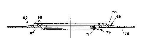
there is provided a lubricant restricting device 65 (Fig. 4-6) gen-
erally positioned between the mounting plate 39 and the back side 66
~;~ of the pinion gear 14. As shown in Fig. 5 the restricting device 65
: - 8 -
;~', ' :
~ i
., .
. - ;~ ` , ".: : . - :
~: .. , .. : :: : :
~ ~7~
may be molded from a resilient material, such as an elMstomeric
or semi-elastomer material, snd may include a base indicated
generally at 67 and first barrier means in the form of lip means
' 68. The base may be clrcular in shape and the lips may be in the,!, form of spaced apart conçentric circles.
To reduce lubricant flow in the space 61 between the pinion
gear 14 and the mounting plate 39, the lips may extend so as to
provide lnterference contact with the gear side 66 as indicated
in Fig. 4 at 68' (shown in uncompressed state). As a further aid
10 in dlverting the flow of lubricant between the pinion gear 14 and
the mounting plate 39, the base 67 may haue a tapered area 69
` leading to a ~lightly thicker concentric front face portion 70
as the base extends radially inwardly toward a center bore or
opening 71 (Fig. 6) through which a reduced diameter extenslon 72
(Fig, 4) of the armature shaft 12 proJects.
`' Bore 71 in base 67 tapers radially outwardly and upwardly
to somewhat follow the shaft flllet 73 as it progrefises from the
front face 70 of the base toward the back side 75 (Fig. 6). The
back side 75 of the base is generally flat so as to nest against
20 the front side 76 (~ig. 3) of mounting plate 39. The outer wall
,
of bore 71 provides a proJection or catch 79 as it extends above
~j or beyond the plane of the back side 75. The catch 79 nests or
extends into the shaft bore 80 (Fig. 4) in mounting plate 39. In
~' other words, the catch 79 extends under (or inwardly) of the plane
~', of the mounting plate's face 76.
In function, the catch or ledge 79 serves to collect any
lubricant which might migrate or be forced along the back side 75
., .
~ of the restricting device 65, particularly from the top downwardly
1, '
9 _ ,
.
Z18 a rcsult of the lubrlcant splash shown at P (Flg. 2). Such
lubrlcant can then flow clrcumferentlally around the catch 79 to
approxln~ately the 6:00 o'clock positlon where lt cun elther run
behind the ba~e 67 or be returned ln the direction X tFig. 3) to
the gear case via inner drain port 49. To provlde maximum re-
slstance to lubrlcant flow, the clearance between the tapered
bore 71 of the restrlcting devlce and the armature shaft fillet 73
should be kept as small as possible without touchlng or providing
a rubblng effect whlch could score the shaft.
For purposes of mounting, the lubricant restricting device 65
may be provided with holes or slot8 80 (Fig. 5) through which
bolts 80' (Fig. 10) of the armature seal assembly 40 may extend to
also clamp tha device in place.
As a further feature of the lnvention,to reduce the aspir-
ating and/or splash losses encountered when gear lubricant in the
bottom of the gear case ls sprayed ln the pattern shown at V
(Flgs. 2 and 3) as the bull gear 15 rotates in the direction R,
:
the restricting device base 67 is provided with means 81 (Fig. 4
' for shielding the inner drain port 49. This means may extend in
~i 20 front of the drain port 49 to block a portion of it from direct
~" splash V but yet allow lubricant drainage from the drain port 49
` through a narrowed channel 82. Another shieldlng means variation
is shown in Figs. 7 and 8 wherein a slightly raised duct or
channel 83 ls used which bulges away from the face of the base 67
' ~ and toward the inside of the gear case. (The location of the ralsed :~-
`~! duct B3 ls also shown in dotted lines on Fig. 5).
'i
Another alternate embodiment of the invention is 6hown at
! 85 in Figs. 9 and 10 wherein a single lip 86 is used in place of
~ .
;'
'.,',
: I :
:,~ ::'' - : .`': ` : ' '
'~:~ :- ': . ' , -
:::.~: ~, ~ ,,
~7;~
a series oE lips as in the embodiment of Figs. 4-6. The lip 86
difEers in that lt diverges radially away or outwardly from the shaft
12 as it extends from the retaining device base 87 toward the side
66 of the plnlon 14. In other words, the llpitip 88 (Fig. 10)
(which is adapted to engage the side 66 of the pinion gear) has a
greater dlameter than lts connectlng ~uncture point 89 with base 87.
, In effect, the outside surface of lip 86 forms a "V"-shaped trough
90 into which lubricant can pool. The lip thl~s restricts lubricant
flow between the gear side 66 and mounting plate 39.
To permit the lip 86 to accommodate different varlations in
the space 61 (Fig. 4) between the gear side 66 and mounting plate 39,
the base 87 behind the lip 86 may be relieved to provide a pocket 90
into which the lip may deflect and nest. Thus, if the pinion gear
14 is advanced excessively along the armature shaft extension 72
toward the mounting plate 39, the lip 86 may fold into the pocket 90.
; The embodiment of ~igs. 9 and 10 also differs from that of
~igs. 2-8, by showing the restricting device 85 installed on a
mounting plate 39 having two drain ports indicated by dotted lines
at 49'. These ports are arcuately dlsplaced slightly on both sides
2~ of the bottommost bolt at the 6:00 o'clock position.
Shielding of the drain ports 49' is provided by overlaid
bosses 91 in the de~vice having narrow slots 84 which extend sub-
stantially the length of the drain ports 49 of the mounting plste
~, 39 but are of a reduced height to restrict lubricant splash into
`1 '
such ports. The bosses or raised areas 91 extend away from the~ base
~:i
87 toward the gear to further shleld direct lubricant flow toward
:
the ports 49',
'~.', - 11 -
~ .,'
,, :
~: 1 ' ' '
: . ~ ;
,. . .
. . . , - , , -
`, ~
, ~ :
- ~ ~7~3~i~
For purposes of accommodating differences ln thermal
expanslon and contraction between the steel of the mountlng
plate 39 and the non-metal materlal of the restricting device
85, there is provided a novel securlng means 92 for attaching
the restricting device (Flgs. lO and 11).
The securing means 92 is shown fastenlng the restrictlng
device 85 and the mounting plate 39 to the labyrinth plate 45.
The mountlng plats 39 has a counterbored hole 94 followed by a
reduced diameter ho].e area 95.
In addition to the bolt 80', the securing means 92 includes
a sleeve 96 havlng a shank 97, a flanged head 98, an internal
bore 99 and an undercut or recessed groove 100 below and of a
smaller diameter than the outside diameter of the shank 97 and
flanged head 98. In use~ a securing means 92 i9 inserted in
holes 102 of the restricting device 90 that its base 87 is held
at about the 6:00 and 12:00 o'clock positions respectively.
~loles 102 may be made slightly larger than the diameter of the
recessed groove lO0 so that slight floating movement of ths base
87 due to thermal expansion can be accommodated when the re-
stricting device is subiected to varying operating temperatures.
Preferably the holes 102 are of smaller diamster than the
out~lda diameter of shank 97 to in effect capture the base 87
in the groove 100 between the larger diameters of the flange 98
and the shank 97. However, the width of the sleeve groove 100
in an axial direction parallel to the bolt length is slightly
~,, greater than the thickness of base 87 ad~acent the bolt area
i so a6 to also allow the floating movement.
',', ' :.'
-- 12
~1 ,
. . . ;: . :, ,
,. ::
::- ;::::
3~i~
Bolt 80' is secured wlthin the sleeve by,a!swaged or
pinched area 101 (Pig. 10). ~hen bolted down, the underside
of the bolt head 80' bears against the bushing flange 98 to
urge the lower end 103 of the shank 97 into contact wlth the
bottom shoulder 104 of the counterbore 94. This firmly clamps
i the mounting plate 39 against the baffle ring 47 and labyrinth
plate 1!5 with the proper bolt stretch while permitting the
restricting device base 87 to float with thermal expansion.
The hole 102 in the base ô7 at the 6:0Q o'clock position
in some cases might have a closer fit to the diameter of the
recessed groove 100 to provide a more positive locatlon at the
6:00 o'clock position but allowing for the thermal expansion or
contraction to be accommodated with the larger clearance of the
hole 102 relative to the groove 100 at the 12:00 o'clock posi- -
tion.
~ile the bolt 80' and 81eeve 96 are shown as separate
'j items, they of course can be made as an integral assembly as
shown at 106 in Fig. 11.
A furtber alternate embodiment of the invention ls shown
in Figs. 12 and 13. This emboddiment is somewhat similar to
l the embodlment shown in Figs. 4-6 and further incorporates a
; diverting means or second barrier means 110 extending from the
lubricant restricting device 109 and overhanging and at least a
~, . .
portion of the pinion gear 14 (Fig. 13).
~' The diverting means 110 may include a web or leaf section
111 extending from the base 67 lnwardly into the gear caselfrom
a point adjacent the mounting.plate 39. The web or leaf 111 may be
~`. generally arcuately formed ln truncated conica] form. As shown, the
web diverges radially away or outwardly from the axial centerline
:' ' ' '
:: i .
~ ":` '
- 13 -
: .
. ~,.'~ ' :
:;' :., :
. :.
~: , , ' - :'' -,: ,~-
ff~f~j~
13 of the armature shaft 12. Preferably the web overhangs the
pinlon 14 for as grea~ an arc as possible so as to reduce the
lubricant spla~h effects "P" and "V" shown in Fig. 2.
In the embodiment shown, the web 111 extends to where it
wil] be in close proxlmity to the mesh of the pinlon 14 and bull
gear 15 without touching the latter. Thus the arc may extend in
the nature of 275". The web in effect forms a "V"~shaped trough
or channel 112 in combination with the O.D, 39' of the mounting
plate 39 and the gear case side 29 in which lubricant may collect
or be diverted. Lubricant may thus be diverted away fro~ the
space 61 between the pinion 14 and the restricting device 109.
~,, It will also be noted in Figs. 12 and 13 that the web 111
also extends below and under the drain slot 113 ln the base 67
' which in turn communicates with the inner drain port 49 in the
i mounting plate 39. The web thus further shields the draln port
from direct lubricant splash V when the bull gear 15 la rocnting
~Fig. 2) in the dlrection "R". In the opposite bull gear r,otation
"S", gear lubricant is thrown over the top of the pinion 14 tas at
, ~P") and collected by the web 111 and diverted from running
; ~ 20 directly between the pinion gear 14 and the mounting plate 39.
As another feature of the invention, to further restrict
; the flow of lubricant into the space 61 between the pinionlgear 14
and the mounting plate 39, there may be provided an additional or
third lubricant barrier means in the form of a deflector llS (Flgs.
14-16). The deflector 115 may pro~ect toward the inslde the gear case
from the base 67 and have a top wing 116 and a bottom wing 117 which
.
straddle and overhang pinion gear 14 ad~acent its meshing area with
bull gear 15. In other words, the deflector wings 116 and 117 proJect
inwsrdly toward the interlor of the case and overhang the pinion
- 14 -
~''` , ' ';
., .:.: :. : :. .: .
: ~ : - . .::
~ ~'7~i8
gear so as not to touch ita teeth.
In the embodiment shown, the deflector wing 116 extends
in a chordal direction relative to the circumference of pinlon
14, i.e. from a point 118 ad~acent the top termination of the
web 111. Bottom wing 117 in similar manner extends from ad-
~acent the lower termination 119 of the web 111.
As shown in Fig. 15, the deflector wings 116 and 117 may
proJect inwardly or overhang the pinion gear 14 approximately
the same distance as the web 111. To accommodate chunks of
hard gear lubrlcant which may be present as a result of cold
weather shut-down perlods, the wings 116 and 117 may be made
of a pliant flexible material such as nylon and may be attached
to the base 67 while being spaced slightly from the web 111 as
~, at 120 (Figs. 14-15). This permits a slight flexing or flutter-
ing of the wings relative to the base 67 and web 111.
As an additional barrier to the flow of lubricant between
I the pinion gear 14 and the mounting plate 39 as indicated at
,l 61 (Fig. 4), the deflector 115 may include a flexible lip 121
which engages the side of pinion 14 and generally extends be-
tween the wings 116 and 117 (Figs. 14 and 15). Preferably lip
121 faces toward the bull gear 15 and is spaced sllghtly from the
wings 116 and 117 as at 122 to pepmit it to flex independently
of the wings. The lip 121 thus engages the 61de of the pinion
14 in chordal fashion somewhat ad~acent the tooth area and the gear
i teeth will actually brush past the lip. It is therefore desirable
that the lip 121 extend slightly beyond the teeth in a chordal
direction to reduce any catching tendency on the teeth.
A further embodiment of the invention is shown in Figs. 17-20,
.' ~ , .
~, ', .
- 15 -
'", , :
. .
. . ... .. .. .
. :.~ ;.. .
:. .
:
. .
wherein ndditional shielding means for the mounting plate drain
port 49 are shown. In this embodiment, a houslng or cover 124
surrounds the drain opening 113 in ~he base 67 and may extend
; outwardly from the base generally as far as the web 111. ~dousing
124 may include side walls 125, a top wall 126, a bottom wall 127
(may be formed by a section of the web lll), a back wall 128
formed by a portLon of the base 67 and a front wall 123. In some
instances it might be desirable to extend the housing 124 a greater
i distance under the pinion gear to enable it to move farther away
, .
, 10 from the gear lubricant concentration which gathers ad~acent the
gear case side walls 28-33, etc.
~, A means for draining the lubricant from the housing is provided
by an aperture 129 in the bottom wall 127. To prevent lubricant
splash V (Fig. 2) from bull gear 15 from being directed through
aperture 129 (particularly when it is moving the direction R),
there may be provided a first moveable flap 130 which covers the
aperture. Flap 130 is preferably hinged as at 131 (Fig. 19) on the
rl side of the aperture 129 toward the bull gear 15 so lubricant flow
in the direction V will tend to slide past the flap and provide a
2 20 lifting or closing action. In other words, the flap 130 is, in
effect, held in tight sealing engagement with the underside of
web 111 along its hinge area 131.
As 8hown in Fig. 19, bottom flap 130 normally hangs open 81ightly
`~ .
, with a slight gap as at 133 to provide drainage. ~ven with lubri-
- cant low in the direction V, the flap 130 may be made to provide
a slight gap for drninage of lubricant returning via the mounting
, ~ plate port 49 (Fig. 4) into the housing 124. However, dlrect flow
or splash of lubricant into the aperture 129 is eliminated since the
, ............................................................... .
:~, .
. . ~
- 16 - ~
1 ' . :.
. 1
.:'~1 .
, .......
. . ~ ..
. .. .
.... .: . ` ~ . `
flap 130 is larger than the aperture 129 and thus extends beyond
the aperture.
! To provlde further restriction to lubricant splash which may
pass the bottom or flrst flap 130, an upper or second moveable
flap 135 may be used to cover the drain opening 113 in housing
back wall 128. Flap 135 may be some~dhat vertically disposed and
hinged ad~acent its top as indicated by dotted line8 at 136 to
enable it to movs outwardly from the back wall 128 toward the
front wall 123. Any lubricant sputtering or gplash entering
through the housing aperture 129 and hitting the front of the
flap 135 will have a tendency to cause the flap to seat against
the back wall 128. A flange 137 (Pig. lô) may be formed to flare
outwardly from the flap 135 along lts lower edge to provide a
small gap 138 for some drainage while heavier drainage will cause
the flap 135 to spring away from the drain opening 113.
Flaps 130 and 135 thus, in effect, serve as valve means to
eliminatq or limit flow in one direction while permitting greater
~, flow in the opposite direction. This is particularLy helpful for
rotation of bull gear lS in direction "R", where the gear in
addltion to splashing lubricant has been found to act like a fan
and produce a positive air pressure effect toward the drain port
~' 49 (Fig. ~I) resulting in air flow carrying lubricant through the
1 dFain port 49,
As will be apparent in Fig. 18, the bottom aperture 129 is
offset away from the housing back wall 128 (and the flange 137
of the uppçr,flap) so any splatter passing through the bottom
aperture 129 wili not be directly in line with the gap 138.
While the various lubricant barrier mean8 are shown to be
incorporated as with the lubricant restricting device 65 and 85
~ 17 -
.
, ' '` ''~
`
:, ...
`: , .: ' ' ;
3g~i~
etc. of the lnvention, lt wlll be apparent that the concepts of
the invention might also be incorporated as part of the mo~mtlng
plate 39 or as part of the gear case. Moreover, although the
invention has been described in terms of certain speclflc embod-
ments, lt -19 to be under6tood that other forms may be adopted
wlthln the ~cope of the lnventlon a6 deflned ln the appended clalms.
.''.',' ' ' '.
:,
~,
.`:i
.:.
} : ~
. ~
.
q,: :
'
i, l
: ~`:.,
C ~ j; r;
,.
:- ~
.. . .... . .. . . .
. .
. ~ -
-
.