Note: Descriptions are shown in the official language in which they were submitted.
~7~
-- 1
The present invention relakes to an arc-heating type
extra-furnace refining apparatus arranged such that
electrodes are immersed in slag on molten steel in a ladle to
thereby form an arc between the electrodes and the molten
steel to heat the molten steel. More particularly, the
invention is concerned with an arc-heating type extra furnace
refining apparatus in which the sealability between the
covering of the ladle and the electrodes is improved.
The object of the invention is to provide an arc-
heating extra~furnace refining apparatus which has improved
sealability between the electrodes and the covering of a
ladle involved, thereby enabling the prevention of nitrogen
pickup as well as eliminating the reoxidation of molten
steel, and thereby enabling a reduction in the amount of
sealing gas used.
An arc-heating extra-furnace type refining apparatus
in accordance with the present invention comprises:
a ladle, capable of receiving molten steel therein;
a rod-like electrode adapted to be immersed into
slag on molten steel within the ladle so as to form an arc
between the electrode and the molten steel;
a covering over the ladle having insertion holes
accommodatiny the electrode therein;
sealing means disposed on the insertion holes and
having a first sealing memher slidably fitted onto the
: electrode in the longitudinal direction thereof and a second
sealing member disposed in such a manner as to hermet~ally
......
, -
..
'
3q3~
seal both the first sealing member and the ladle covering and
provide a gap between the second sealing member and the
electrode;
the second sealiny member having an inclined gas
injection nozzle formed in the second sealing member and
aligned to discharge a jet of gas in a direction inclined at
an angle of at least 10 away from a plane which includes the
axis of the electrode, whereby the gas is injected from the
inclined gas injection noz21e to form a flow rotating around
the electrode: and
gas supplying means ~or supplying a gas to the
inclined gas injection nozzle for discharge therefrom at a
rate of at least 100 Nm3/hour.
By means of the present invention, it is possible
to maintain the ladle interior in a highly sealed condition
and arc-heat the molten steel in this condition, and yet
provide a seal which does not rapidly deteriorate with time.
Further, sealing can be maintainecl even when the electrode is
moved about. As a result, nitrogen pickup by the molten
steel during the arc process (AP) can be decreased to 0~05
ppm/min. or less.
This invention can be more fully understood from the
following fletailed description when taken in conjunction with
the accompanying drawings, in which:
Fig. 1 is a sectional view showing a prior
, . . .:
: .:
,: , ' :
. :
,;: ..,: ... ..
. .
~3~
y
art arc-heating type extra-furnace refininy apparatus;
Fig. 2 is an enlarged view showing the electrode
and its neighbouring zone of the refining apparatus
shown in Fig. 1;
Fig. 3 is an enlarged view showing the electrode
and its neighbouring zone of an arc-heating type extra-
furnace refining apparatus in accordance with a first
embodiment of the invention;
Fig. ~ is a plan view of Fig. 3;
Fig~ 5 is a graph showing the effect which is
obtained with the use of the refining apparatus shown in
E'ig. 3;
Fig. 6 is a plan view showing the electrode and its
neighbouring zone of an arc-heating type extra-furnace
lS refining apparatus in accordance with a second embodi-
ment of the invention;
Fig. 7 is a vertical sectional view oE Fig. 6;
E'igs. 8 and 9 are graphs which show the effects
obtainable with the use of the refining apparatus shown
in E'i~J~ 6;
E'ig. lU is an enlaryed sectional view showiny the
electrode and its neighbouriny zone Oe an arc-heating
type extra-furrlace reEining apparatus in accordance with
a third embodiment of the invention;
Fig. 11 is a plan view of the refining apparatus
shown in ~iy. 10;
E~ig. 1~ is a graph which shows the effect
obtained with the use of the refining apparatus shown in Fig.
10 ;
Fig. 13 is a sectional view of an arc-heating type
extra-furnace refining apparatus in accordance with a fourth
embodiment of the invention; and,
Fig. 14 i5 a plan view of the refining apparatus
shown in Fig. 13.
In the arc process (hereinafter, referred to simply
as "AP") of making an extra-furnace refinement of molten
steel tapped from a converter, as shown in Fig. 1, electrodes
8 are immersed in a slag 6 on molten steel 4 charged into
ladle 2 and an arc is formed between the molten steel and the
electrodes to heat the molten steel. Simultaneously, lance
10 is immersed into the molten steel to thereby introduce a
gas into the molten steel to stir the same. In this case,
since lid or covering 12 is set on ladle 2, electrodes 8 and
lance 10 are inserted into the ladle via insertion holes 1~
provided in covering 12. At the top of ladle 2, dust
collecting duct 15 is mounted, which is intended to col]ect
exhaust gas containing the dust which is produced at the time
of heating the molten steel or stirring the molten steel by
bubhling or conducting powder in~ection.
'
",-
. .
,.;
Meanwhile, since electrodes ~ are kept at ahiyh temperature and supplied with a high voltage, a
small gap is allowed to exist between each electrode 8
and covering 12. For this reason, the Elame which
has been generated in the vicinity of the electrode
portions within the ladle comes outsicde via the
gaps. This flame causes an upward flow of the gas
in the ladle as indicated in Fig. 1 by arrows which
causes atmospheric air to be sucked into the ladle
through, for example, seal 16 between covering 12 and
ladle 2. As a result, reoxidation of the molten
steel takes place in the ladle and, at the same -time,
the content of nitroyen [N] in the molten steel
increases with the result that what is called "pickup"
lS occurs.
In order to prevent the occurrence of the [N]
pickup phenomenon, as shown in Fig. 2, refractory
board 18 made of ceramic Eiber is disposed between
electrodes ~ and the~ covering 12 to thereby seal the
gap therebetween. This sealing means, however, has
a drawback in that refractory board 1~ faLls to
function as a sealing means in the final half of AP
because it is damaged by the ~lame which has been
generated in the beyinning stage of arc-heating.
For this reason, where the gap between the electrode
and the covering is sealed with the use of the
refractory t~oard, a [N] pickup of 0.25 to 0.75 ppm/min.
still occurs.
On the other hand, a method of blowing Ar gas onto
the portions of electrode.s 8 in the vicinity of insertion
holes 14 to thereby seal the gap between the electrodes and
the covering can also be contemplated as a countermeasure.
This gas seal, however, fails to have a sufficient sealing
function because the Ar gas is pushed upwards by the upward
flow of gas coming out of insertion holes 14. For this
reason, the conventional sealin~ means fails to sufficiently
prevent the reoxidation of the molten steel as well as not
preventing the pickup of (N} and, in addition, requires the
use of a large amount of seal gas (Ar gas). In this old
sealing means, it is necessary to use Ar gas of, for example,
approximateiy 300 Nm3/hour or more and this becomes a factor
of increasing the refining cost.
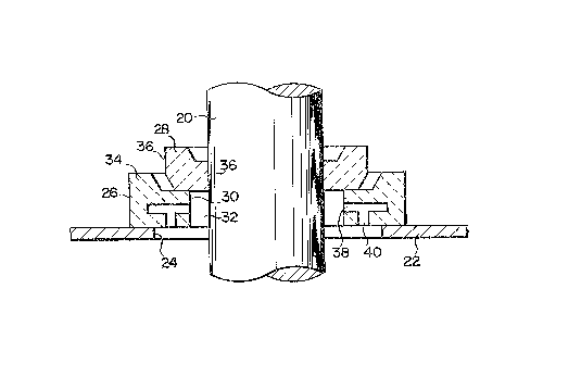
In the first embodiment of the invention shown in
Figs. 3 and 4, rod-like electrode 20 is inserted into the
ladle via insertion hole 24 which is formed in covering 22 of
the ladle and which is circular in cross section. On
covering 22 in vicinity of the insertion hole 24, annular
base seal 26 is installed, which constitutes a second sealing
member. On this base seal 26, annular cap seal 28
constituting the first sealing member is installed in a
manner that it is slidable with respect to base seal 26.
Base seal 26 has an inner diameter gre.ater than the outer
diameter of electrode 20 and an outer diameter greater than
the diameter of insertion hole 2~. Base seal 26 i5 installed
on covering 22 in a manner such that it is inserted over
electrode 20 so that small yap 32 may be formed between its
inner peripheral surface 30 and the outer surface of
electrocle 20. Annular embossecl portion 34 is formed on the
outer peripheral edge portion of base seal 26 over the entire
circumference thereof.
"~ , , .
:` ~' ' '`
~-~73~34~
Cap seal 28 has an inner diameter substantially e~ual
to the diameter of the electrode 20 Accordingly,
cap seal 28 has its inner peripheral surface 36 in
to slidable contact with electrode 20 and thus is
made movable in the longitudinal direction thereof.
On the other hand, the outer diameter of cap seal
28 is greater than the inner diameter of base seal
26. Eor this reason, cap seal 28 can be engaged
with base seal 26. Eurther, since outer peripheral
surface 36 of cap seal 28 is smaller in diameter
than the inner wall surface oE embossed portion 34,
cap seal 28 can slide on the base seal 26 in the
area surrounded by annular embossed portion 3'~.
Base seal 26 and cap seal 28 can be formed
using, for example, a refractory having a composition
of, alumina (AQ2O3) 90% - silica (~iO~) 10%.
~ ase seal 26 is formed in inner peripheral surface
30 with horizontal injection nozzles 38 permittiny
gas to be horizontally injected toward electrode 20,
2U and is also formed on its underside with vertica:L
injection nozzles 4~ permitti.ng gas to be downwardly
injected. These injected nozzles 33 and 4~ are con-
nected with an external gas supply source Eor supplying
an inert gas such as, Ar gas. That is, Ar yas is
discharged by way of injection nozzles 38 to forrn a
purge in the horizontal direction to thereby provide
a horizontal gas seal. Additionally, Ar gas is
discharged by way of injection nozzles 40 to form
a purge in the vertical direction to thereby provide a
vertical gas seal as well.
In the arc-heating type extra-furnace refining
apparatus having the above-mentioned construction, when
the molten steel is arc-heated using the arc ormed
between the molten steel and electrodes 20, the flame
within the ladle is preven-ted from coming outside the
same and any upward flow of gas passing through the
insertion hole is also prevented from occurring since
the electrode 20 is hermetically connected with
covering 22 by means of cap seal 28 and base seal
26. Accordingly, s~lction of any atmospheric air
into the ladle is preven-ted and thus it is possible
to minimize [N] pickup as well as the reoxidation
of the molten steel.
Further, cap seal 28 is kept in contact with
electrode 20 and is light in weight and small in
size. Therefore, even when electrode 20 is moved
horizontally, cap seal 28 can slide on base seal 26
in a manner to Eollow electrode 20. Even in such a
case, there~ore, a state of sealing can be maintained
between electrode 20 and covering 22. ~n the other
hand, when electrode 20 is vertically moved, cap seal
28 can slide along electrode 20 in the longitudinal
direction thereoE. In this case as well, therefore, the
state of sealing can be maintained.
.,
:. .
:
~73~
Further, according to this first embodiment, since
the Ar gas is discharged through injection nozzles 38
to form a horizontal gas seal, the flame which rises
upwards from the interior of the ladle is cut off by
such horizontal gas seal. Further, since the Ar gas
is discharged through injection no~zles ~U to form a
vertical gas seal, even when the molten steel is
splashed upwards over the zone located in the vicinity
oE insertion hole 24, the splashed steel prevented
from clinging to electrode 2~ or covering 22.
In this way, according to the present invention, it
is possible to avoid the occurrence of any operational
trouble as well as to prevent not only the occurrence
of [N] pickup but also the reoxidation of the molten
steel. Table 1 below shows examples in which molten
steel is arc heated using the arc-heating type extra-
furnace refining apparatus in accordance with the
Eirst embodiment of the invention, while Table 2
below shows comparative examples in which molten
steel is arc heated using a prior art refining
apparatusl
~_~73~L~
-- 10 --
Table 1
_ __ ._ , _ ~
No. Treating Content Rate Flowrate ~econdary
Time In of [N] of [NJ- of Ar Voltag~
AP Pick-up Pick-up Gas
_ _
1 45 2 0.04 250 360
52 1 0.02 200 310
3 S0 0 0 200 310
4 4~ 2 0.04 230 360
S 42 1 0.02 240 360
6 39 0 0 230 410
7 55 1 0.02 18~ 310
~1~ 2 0.04 190 360
9 49 0 0 200 ~6()
39 0 0 ~00 41~
11 54 1 0.02 230 310
:L2 56 ~ 0 200 310
13 50 ~ 0.04 190 310
14 49 1 0.02 20~ 360
47 2 0.04 230 360
16 55 1 0.02 22~ 310
17 35 1 0.03 ~00 41~
18 53 0 0 210 310
1'~ 4~ 0 0 220 360
1 0.02 170 310
~1 4~ 1 0.02 1~0 36~
_ __
., ~
:
73~?4~
-- 11 --
Table 2
____ _ __ _ _
No. Treating Contant Speed Flowrate Secondary
Time For of [N~ of [N]- of Ar Voltage
Ar Gas Pick-up Pick-up Gas
S ,
1 51 23 0.45 300 310
2 50 13 0.26 300 310
3 45 26 0~58 280 360
4 46 19 0.41 290 360
1~ 5 52 17 0.33 280 310
6 55 16 0.29 280 310
7 49 35 0.71 2~0 360
48 34 0.71 310 360
9 51 32 ~.63 300 310 .
42 21 0.50 290 36~
In the above Tables 1 and 2, the treating time
in A~ is expressed in units oE minutes; the [N] pick
up content in units of ppm; the rate oE [N] piclcup in
units Oe ppm/min.; the :Elowrate oE Ar gas in units of
NQ/min.; and the level o:E secondary voltage in units oE
vo:Lts. Li`urther, the lad:le has a volume of 250 tons; the
electrode has a diameter of 18 inches; and the maximum
rate at which the temperature oE molten steel is raised
is 4.5C/min.
The results of the above-mentioned examples and
3S~
- 12 -
comparative examples are shown in Fig. 5 in which the
treating time in AP is plotted on the abscissa and
the [N] pick up content (ppm) on the ordinate. As
apparent from Tables 1 and 2 and the graph shown in
Fig. 5, according to the examples of the invention, the
speed of [~1 pickup is as low as 0 to 0.05 ppm~min. and
the increase in [N] content per treatment is as small as
0 to 2 ppm. In contrast, according to the comparative
examples, the speed of [N] pickup is as high as 0.25 to
0.75 ppm/min. and the increase in [N] content per
treatment is as larye as 13 to 35 ppm.
A second embodiment oE the invention will now be
described. This second embodiment differs from the
preceding first embodiment in that the direction of
ejecting a seal gas is so set as -to cause the flow
thereof to rotate around the electrode; about the
lengthwise axis thereoE. This enables the enhancemen-t
of the sealability and, at the same time, enables a
reduction in the amount of the seal gas used. Figs. 6
and 7 show an arc-heating type extra furnace refining
apparatus in accordance with the second embodiment of
the invention. In these Eigures, the same parts or por
tions and members as those used in ~igs. 3 and 4 (first
embodiment) are denoted by like reference numerals, and
description thereof is omitted.
Base seal 42 is formed on the interior with a pair
of gas flow passages 44 along the half circles using
3C~
electrode ~0 as their center. The gas flow passages
~L4 being connected to an external gas supply source
via gas supply passages 46. Each gas flow passage
44 is formed with a plurality of horizontal injection
nozzles 48 extending in the horizontal direction,
as well as a plurality of vertical injection nozzles
5~ extending in the vertical direction. From horizontal
injection nozzles 48, the gas is purged in the horizon-
tal direction, thereby to intercept the flame rising
upwards from inside the ladle. ~n the other hand,
from vertical injection nozzles 50, the gas is purged
in the vertical direction, thereby to prevent the molten
steel from being splashed over, and clinging to inser
tion hole 24. This prevents sparking from electrode
lS 20.
Each horizontal injection nozzle 48 is inclined at
a specified anyle with respect to the direction
extending from gas ~low passage 44 toward the center
of electrode 20, whereby the gas discharged from
horizontal injection nozzle 48 into the yap between
base seal 42 ancl electrode 20 can Elow in the same
direction in such a manner as to rotate around
eLectrode 20, about the lenythwise axis thereoE. This
rotational Elow of the yas cuts o~E the upwarcl flow of
yas Erom inside the ladle. In order to form a suf-
ficient rotational Elow oE gas around electrode 20,
horizontal discharge bore 48 preferably is provided
3~
- 14 -
at least four in number along the half circles.
E`iy. 8 is a graphic diagram showing the relationship
between the direction of discharge of the horizontal
discharge bore 48 and the sealing characteristic,
which holds true where the flowrate of inert gas is
100 Nm3/hourO In FigO 8, the abscissa represents
the angle at which the discharging direction oE -the
horizontal discharge bore 48 is inclined with respect
to the direction extending toward the center axis of
the electrode 20 while, on the other hand, the ordinate
represents the speed of [N] pick-up as expressed in
terms of (x 10 2ppm/min.). That is, where the angle
of inclination of the horizontal discharge bore 48
is 0, the flow of the gas ejected therefrom advances
toward the electrode 20. As the angle of inclination
increases, the flow of gas is greatly inclined from
the direction extending toward the center axis of
the electrode 20. As clear from Fig. 8, while the
speed of [N] pick-up i5 as high as 0.1 to 0,2 ppm/min.
in case where the angle of inclination is 0, the
speed of [Nl pick-up becomes lower as the angle oE
inclination increases to cause the formation of a
stronger rotational flow of inert gas. As seen in
~'iy. ~, if the horizontal discharge bore 48 is inclined
~5 at an angle of 10 or more with respect to the direction
extending toward the electrode 20, then the rate of
pick-up oE [N] can be greatly slowed down as compared
.~ .
with a case where the flow o:E the gas discharged is
clirected toward the electrode 20.
With the arc-heating type extra-furnace refining
apparatus having the above-mentioned construction,
molten steel is arc heated using an arc formed between
electrode 20 and the molten steel, flame rises from
inside the ladle toward electrode insertion hole 24
the molten steel is splashed toward electrode hole
24. However, inert gas is being supplied into gas
flow passages 44 via gas supply passages 46 connected
with the external gas supply source, the inert gas
being discharged on and around electrode 20 via
horizontal injection nozzles 48 and vertical injection
nozzles 50. The inert gas discharged from vertical
injection nozzles 50 is vertically discharged downwards,
thereby to prevent the molten steel from splashing
toward electrode insertion hole 24 and from clinglng
in the neighbourhood of insertion hole 24. On
the other hand, the inert gas which is discharged
from hor:izontal nozzles '~8 into the annular gap
between electrode 2~ and base seal 42 flows in
such a manner as to rotate in one direction (in the
counterclockwise direction in Eig. 6) around electrode
20. This horizontal rotational flow of inert gas
acts to cut off the flame rising upwards from inside
the ladle, thereby preventing any upward flow of
gas passing through insertion hole 24. Accordingly,
~3~
~ 16 -
the interior of the ladle is kept under positive
pressure due to the Ar gas and any atmospheric air
is prevented from being sucked into the ladle from
between the covering and the ladle. F'or these
reasons, the molten steel is prevented from being
reoxidated and, at the same time, from undergoing the
pickup of [N].
Fig. 9 is a graphic diagram showing the effect
of the invention, showing the relationship between
the amount of inert gas discharged and the rate
of pickup of [N] in the case of using the gas sealing
means described hereinabove in connection with the
second embodiment of the invention. Measurement
data was obtained when molten steel was heated at
a maximum molten-steel temperature raising rate of
~1.5C/min. by using an arc-heating type extra-furnace
refining apparatus in which the ladle has a capacity of
250 tons; the transformer has a capacity of 35,000 kVA;
the secondary voltage has a level of 310 to 51~ V;
and the electrode has a diameter of 18 inches. In
the graph oE F'ig. '3, the circles represent the
measurement data which have been obtained when the
yas discharying direction is inclined with resuect
to the direction extending toward the electrode
in accord~nce with this sècond embodiment, while
the dots represent the measurement data which have
been obtained by blowing the gas toward the gap
'~ ,,
~;~ 7 3 ~
be~ween th~ electrode and the covering as in conven-
tional method. The arc heating time is ~0 to 55 minutes
with respect to each measurement. As clear from
Fig~ 9, when the gas discharging direction is in
conformity with the direction extending toward the
center axis of the electrode, the discharging flow of
gas collides directly against the surface of the
electrode, so that the gas flows loses most of its
force. For this reason, the sealing inert gas is
pushed upwards by the flow of gas rising from
inside the ladle, failing to check the intra-ladle
flow of gas advancing toward the insertion hole~
For this reason, as seen in Fig. 9, conventionally,
the rate of [N] pickup is high and in order to
decrease the [N] pickup rate down to a value of
0.05 ppm/min., it is necessary to supply and discharge
the inert gas at the rate of 300 Nm3/hour. In
contrast, according to the invention, when the
discharging amount of inert gas is 100 Nm3/hour or
more, the [N] pickup rate is 0.05 ppm/min. or less.
That is, according to the invention, it is possible
to suppress the [N] pickup rate below the ~uite small
value of 0.05 ppm/min. This is because, in the
present invention, the inert gas discharged from
horizontal injection nozzles ~8 Eorms a strong
rotational flow around electrode 20 to thereby
effectively cut off the flame and upward gas flow
L~
occurring from inside the ladle.
As stated above, according to this second embodi-
ment, a strong rotational flow of inert gas is formed
around the portion of the electrode ln the vicinity
of the insertion hole. For this reason, it is possible
to maintain high sealability between the electrode
and the covering to be to thereby effectively cut
off the flame and upward gas flow occurring frorn
inside the ladle. Accordingly, it is possible to
maintain the interior of the ladle under positive
pressure to thereby prevent and atmospheric air from
being sucked into the ladle. Accordingly, it is
possible to effectively prevent the pickup of [N]
in the molten steel as well as the reoxidation of
the same. Accordingly, it is also possible to decrease
the amount of inert gas intended for use in sealing
and thereby to reduce the refining cost.
Next, a third embodiment of the invention will be
described with reEerence to E'igs. 1~ and 11. In this
2U third embodiment, the base seal member designed to
eject the seal gas is made into a water-cooled structure
with the aim of Lengthening its service life. Base
seal 5~ is Eormed with cooling water passages 56.
These passages are Eormed in such a manner as to
pass through almost all of the central region of
base seal 52 (as viewed in the thickness wise
direction) without crossing gas passages 44 and ~8.
Further, caU seal 54 also is formed with cooling
water passage 5~.
In the arc process (AP), after the covering is
se-t on the ladle in which molten steel is received,
cooling water is caused to ~low through cooling-
water passages 56 and 5~, thereby cooling base
seal 52 and cap seal 5~. Subsequently, while base
seal 52 and cap seal 54 are thus being cooled by
water, seal gas is caused to flow through gas
passages 44 and 48 to thereby seal the electrode,
thus facilitating the arc process. Due to the water
cooling procedure base seal 52 and cap seal 54 are
prevented from being impaired or damaged from the
heat of the molten steel and arc. That is, where
the refining apparatus has no water-cooled structure,
the base seal and cap seal are thermally damaged
to a comparatively large extent and must actually
be re~laced after 15~ to 2~ charges. According
to this third embodiment, however, the rate at
2~ which the base .sea:L and cap seal are thermally
worn is very low, enabliny their use in up to
approximately 10~0 charyes. Fig. 12 shows the
relationship between the frequency of uses of the
base seal and cap seal and the [N] pickup rate, by
comparing the use of the base seal and cap seal in
accordance with this third embodiment with the use
of the base seal and cap seal having no water-cooled
J
.
'. ,.
- 20 -
structure. As seen in Fig. 12, according to this
embodiment, it is possible to stably maintain the
[N] pickup rate at small values and any measurable
increase in the [N] pickup rate was not recognized
until after approximately lUOU charges was completed.
~imilarly, it is also possible to simultaneously
suppress the reoxidation of the molten steel.
Next, a fourth embodiment of the inven-tion will
be described. This fourth embodiment is directed
lU toward improving the dust collection hood installed
above the ladle so as to decrease the pickup of [N]
in the molten steel. That is, as shown in Fig. 1,
a conventional dust collection hood is provided on ladle
2 in such a manner as to cover the ladle. This hood,
however, is opened at the bottom and is mounted directly
on covering 12. E`or this reason, when the amount of
suction air intended for dust collection is increased, a
negative pressure is produced within the ladle which
promotes the attraction of atmospheric air into the
2~ ladle. As a result, the rate oE pickup of [N] in the
molten steel is increased. The fourth embodimerlt is
intended to eliminate this problem. Referring to
Figs. 13 and 1~ showing the Eourth embodiment of the
invention, dust collection hood body 6U is shaped like
a box and is installed above ladle covering 22 with
specified gap S being provided between hood body 6U
and covering 22. This gap is constituted of a
~ ~ 72~
layer of a~mospheric air. Electrodes 20 are passecl
through body 60. Electrode holes 62 are formecd at
the upper side of the body 60 and electrode holes
which serve as suction holes 64 are ormed at the
lower side. Accordingly, suction holes 6'~ are
provided above insertion holes 24 of ladle covering
22. Body 60 can have any given height H which permits
any upward flow of exhaust gas to be sufficiently
trapped inside the body. Body 60 is formed at the
side periphery with joint ports 66 to which dust
collection ducts are connected. Joint ports 66
are providecd in the number equal to that of suction
holes 64. ~ince, in this embodiment, the number
of electrodes 20 or suction holes 64 is three, the
number of joint ports 66 is also three.
With the above-mentioned construction, the exhaust
gas containing dust therein which is discharged Erom
insertion holes 2~ is sucked into body 60 via suction
holes 64. ~ince body 6U can have any given height
2~ large enoucJh to permit the exhaust gas to be suf-
ficiently trapped inside body 60, the exhaust gas
is effectively trapped inside body 60 and is sent from
joint ports 66 to the dust collection ducts. ~ince
joint ports 66 are provided in number equal to that
Oe suction holes 64, the dust collection is also
effectively performed.
Body 60 is box-shaped and therefore has
. .,
~., ' ,.......... .
~ ~73~
excellent airtightness, so that the suction is performed
efficientlyO Further, body 60 is mounted above ladle
covering 22 in such a manner that it is spaced away
from the latter without making con-tact thereto. As
a result, the interior of ladle 2 is prevented from
having a negative pressure, so that the attraction of
air into the ladle is impossible.
Conse~uently, it is possible not only to enhance
the dust collection efficiency but also to prevent
nitrogen gas from being picked up by the molten steel.
According to the experiments performed by the pre-
sent inventors, it has been proved that, in the case of
the prior art dust collection hood 15 (Fig. 1), even
when the dust collection damper has an opening of lOU%,
dust escapement is considerable. In the case of the
above-mentioned present dust collection hood, however,
suEficient dust collection is possible with the dust
collection damper having an opening of only 70 to ~0~.
Further, the dust collection hood is also Eollowed by
a rernarkable power reduction re~1uired by the dust
collector blower involved. Ei`urthermore, the use of this
dust collection hood made it possible to reduce the (N)
pickup speed from 0.3U ppm/min., which is a conventional
value, down to O.lU ppm/min. which is approximately 1/3
of the Eormer value.